

flow and level measurement - Omega Engineering
flow and level measurement - Omega Engineering
flow and level measurement - Omega Engineering

You also want an ePaper? Increase the reach of your titles
YUMPU automatically turns print PDFs into web optimized ePapers that Google loves.
horizontally, the other vertically,<br />
with gears meshing at the tip of the<br />
vertical gear <strong>and</strong> the center of the<br />
horizontal gear (Figure 3-3A). The two<br />
rotors rotate opposite to each other,<br />
creating an entrapment in the crescent-shaped<br />
gap between the housing<br />
<strong>and</strong> the gear. These meters can be<br />
very accurate if slippage between the<br />
housing <strong>and</strong> the gears is kept small. If<br />
the process fluid viscosity is greater<br />
than 10 centipoise <strong>and</strong> the <strong>flow</strong>rate is<br />
above 20% of rated capacity, accuracy<br />
of 0.1% AR can be obtained. At<br />
lower <strong>flow</strong>s <strong>and</strong> at lower viscosity,<br />
slippage increases <strong>and</strong> accuracy<br />
decreases to 0.5% AR or less.<br />
The lubricating characteristics of<br />
the process fluid also affect the turndown<br />
of an oval gear meter. With liquids<br />
that do not lubricate well, maximum<br />
rotor speed must be derated to<br />
limit wear. Another way to limit wear<br />
is to keep the pressure drop across<br />
the meter below 15 psid. Therefore,<br />
the pressure drop across the meter<br />
limits the allowable maximum <strong>flow</strong><br />
in high viscosity service.<br />
Rotating lobe <strong>and</strong> impeller type<br />
PD meters are variations of the oval<br />
gear <strong>flow</strong>meter that do not share its<br />
precise gearing. In the rotating lobe<br />
design, two impellers rotate in opposite<br />
directions within the ovoid<br />
housing (Figure 3-3B). As they rotate,<br />
a fixed volume of liquid is entrapped<br />
<strong>and</strong> then transported toward the<br />
outlet. Because the lobe gears<br />
remain in a fixed relative position, it<br />
is only necessary to measure the<br />
rotational velocity of one of them.<br />
The impeller is either geared to a register<br />
or is magnetically coupled to a<br />
transmitter. Lobe meters can be furnished<br />
in 2-in to 24-in line sizes. Flow<br />
capacity is 8-10 gpm to 18,000 gpm in<br />
the larger sizes. They provide good<br />
repeatability (better than 0.015% AR)<br />
at high <strong>flow</strong>s <strong>and</strong> can be used at high<br />
operating pressures (to 1,200 psig)<br />
<strong>and</strong> temperatures (to 400°F).<br />
The lobe gear meter is available in<br />
a wide range of materials of construction,<br />
from thermoplastics to<br />
highly corrosion-resistant metals.<br />
Disadvantages of this design include a<br />
loss of accuracy at low <strong>flow</strong>s. Also,<br />
the maximum <strong>flow</strong> through this meter<br />
is less than for the same size oscillatory<br />
piston or nutating disc meter.<br />
In the rotating impeller meter,<br />
very coarse gears entrap the fluid<br />
<strong>and</strong> pass a fixed volume of fluid<br />
with each rotation (Figure 3-3C).<br />
These meters are accurate to 0.5%<br />
of rate if the viscosity of the<br />
process fluid is both high <strong>and</strong> constant,<br />
or varies only within a narrow<br />
b<strong>and</strong>. These meters can be made<br />
out of a variety of metals, including<br />
stainless steel, <strong>and</strong> corrosion-resistant<br />
plastics such as PVDF (Kynar).<br />
These meters are used to meter<br />
paints <strong>and</strong>, because they are available<br />
in 3A or sanitary designs, also<br />
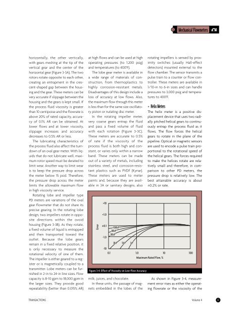
Error<br />
+10<br />
+1.0<br />
0.1<br />
-1.0<br />
-10<br />
>1000cP<br />
300cP<br />
100cP<br />
30cP 10cP 3cP<br />
Figure 3-4: Effect of Viscosity on Low-Flow Accuracy<br />
milk, juices, <strong>and</strong> chocolate.<br />
In these units, the passage of magnets<br />
embedded in the lobes of the<br />
3 Mechanical Flowmeters<br />
rotating impellers is sensed by proximity<br />
switches (usually Hall-effect<br />
detectors) mounted external to the<br />
<strong>flow</strong> chamber. The sensor transmits a<br />
pulse train to a counter or <strong>flow</strong> controller.<br />
These meters are available in<br />
1/10-in to 6-in sizes <strong>and</strong> can h<strong>and</strong>le<br />
pressures to 3,000 psig <strong>and</strong> temperatures<br />
to 400°F.<br />
• Helix Meters<br />
The helix meter is a positive displacement<br />
device that uses two radially<br />
pitched helical gears to continuously<br />
entrap the process fluid as it<br />
<strong>flow</strong>s. The <strong>flow</strong> forces the helical<br />
gears to rotate in the plane of the<br />
pipeline. Optical or magnetic sensors<br />
are used to encode a pulse train proportional<br />
to the rotational speed of<br />
the helical gears. The forces required<br />
to make the helices rotate are relatively<br />
small <strong>and</strong> therefore, in comparison<br />
to other PD meters, the<br />
pressure drop is relatively low. The<br />
best attainable accuracy is about<br />
±0.2% or rate.<br />
0.1 1.0 10 100<br />
Maximum Rated Flow, %<br />
As shown in Figure 3-4, <strong>measurement</strong><br />
error rises as either the operating<br />
<strong>flow</strong>rate or the viscosity of the<br />
TRANSACTIONS Volume 4 37


