

flow and level measurement - Omega Engineering
flow and level measurement - Omega Engineering
flow and level measurement - Omega Engineering

Create successful ePaper yourself
Turn your PDF publications into a flip-book with our unique Google optimized e-Paper software.
of a multi-bladed rotor mounted at<br />
right angles to the <strong>flow</strong> <strong>and</strong> suspended<br />
in the fluid stream on a free-running<br />
bearing. The diameter of the<br />
rotor is very slightly less than the<br />
inside diameter of the metering<br />
chamber, <strong>and</strong> its speed of rotation is<br />
proportional to the volumetric <strong>flow</strong><br />
rate. Turbine rotation can be detected<br />
by solid state devices (reluctance,<br />
inductance, capacitive <strong>and</strong> Halleffect<br />
pick-ups) or by mechanical<br />
sensors (gear or magnetic drives).<br />
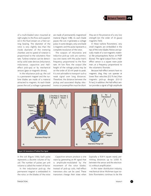
In the reluctance pick-up, the coil<br />
is a permanent magnet <strong>and</strong> the turbine<br />
blades are made of a material<br />
attracted to magnets. As each blade<br />
passes the coil, a voltage is generated<br />
A)<br />
Permanent<br />
Magnet<br />
Cone<br />
Coil<br />
Blade<br />
Meter Body<br />
Reluctance Pickup Coil<br />
Figure 3-8: Generation of Turbine Flow Signal<br />
in the coil (Figure 3-8A). Each pulse<br />
represents a discrete volume of liquid.<br />
The number of pulses per unit<br />
volume is called the meter’s K-factor.<br />
In the inductance pick-up, the<br />
permanent magnet is embedded in<br />
the rotor, or the blades of the rotor<br />
are made of permanently magnetized<br />
material (Figure 3-8B). As each blade<br />
passes the coil, it generates a voltage<br />
pulse. In some designs, only one blade<br />
is magnetic <strong>and</strong> the pulse represents a<br />
complete revolution of the rotor.<br />
The outputs of reluctance <strong>and</strong><br />
inductive pick-up coils are continuous<br />
sine waves with the pulse train’s<br />
frequency proportional to the <strong>flow</strong><br />
rate. At low <strong>flow</strong>, the output (the<br />
height of the voltage pulse) may be<br />
on the order of 20 mV peak-to-peak.<br />
It is not advisable to transport such a<br />
weak signal over long distances.<br />
Therefore, the distance between the<br />
pickup <strong>and</strong> associated display electronics<br />
or preamplifier must be short.<br />
One Pulse<br />
Per Blade<br />
One Unit<br />
Volume<br />
Capacitive sensors produce a sine<br />
wave by generating an RF signal that<br />
is amplitude-modulated by the<br />
movement of the rotor blades.<br />
Instead of pick-up coils, Hall-effect<br />
transistors also can be used. These<br />
transistors change their state when<br />
3 Mechanical Flowmeters<br />
they are in the presence of a very low<br />
strength (on the order of 25 gauss)<br />
magnetic field.<br />
In these turbine <strong>flow</strong>meters, very<br />
small magnets are embedded in the<br />
tips of the rotor blades. Rotors are typically<br />
made of a non-magnetic material,<br />
like polypropylene, Ryton, or PVDF<br />
(Kynar). The signal output from a Halleffect<br />
sensor is a square wave pulse<br />
train, at a frequency proportional to<br />
the volumetric <strong>flow</strong>rate.<br />
Because Hall-effect sensors have no<br />
magnetic drag, they can operate at<br />
lower <strong>flow</strong> velocities (0.2 ft/sec) than<br />
magnetic pick-up designs (0.5-1.0<br />
ft/sec). In addition, the Hall-effect sensor<br />
provides a signal of high amplitude<br />
(typically a 10.8-V square wave), permitting<br />
distances up to 3,000 ft.<br />
between the sensor <strong>and</strong> the electronics<br />
without amplification.<br />
In the water distribution industry,<br />
mechanical-drive Woltman-type turbine<br />
<strong>flow</strong>meters continue to be the<br />
TRANSACTIONS Volume 4 41<br />
B)<br />
Coil<br />
Rotor<br />
Meter Body<br />
N<br />
S<br />
Inductance Pickup Coil<br />
Per<br />
Revolution<br />
Permanent<br />
Magnet


