

flow and level measurement - Omega Engineering
flow and level measurement - Omega Engineering
flow and level measurement - Omega Engineering

Create successful ePaper yourself
Turn your PDF publications into a flip-book with our unique Google optimized e-Paper software.
Because they are very sensitive to the<br />
velocity profile of the <strong>flow</strong>ing stream,<br />
they must be profiled at several<br />
points across the <strong>flow</strong> path.<br />
Insertion turbine meters can be<br />
designed for gas applications (small,<br />
lightweight rotor) or for liquid (larger<br />
rotor, water-lubricated bearings).<br />
They are often used in large diameter<br />
pipelines where it would be costprohibitive<br />
to install a full size meter.<br />
They can be hot-tapped into existing<br />
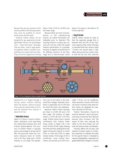
Concentric<br />
Cone<br />
Flow<br />
Straightener<br />
Alternative Flow<br />
Straightening Vanes<br />
Bundle of Tubes<br />
Element<br />
Figure 3-10: Flow Straighteners Reduce Straight Pipe Runs<br />
pipelines (6 in or larger) through a<br />
valving system without shutting<br />
down the process. Typical accuracy<br />
of an insertion turbine meter is 1% FS,<br />
<strong>and</strong> the minimum <strong>flow</strong> velocity is<br />
about 0.2 ft/sec.<br />
• Turbine Meter Accuracy<br />
Figure 3-9 shows a typical turbinemeter<br />
calibration curve describing<br />
the relationship between <strong>flow</strong> <strong>and</strong><br />
K-factor (pulses/gallon). The accuracy<br />
of turbine meters is typically<br />
given in percentage of actual rate (%<br />
AR). This particular meter has a linearity<br />
tolerance b<strong>and</strong> of ±0.25%<br />
over a 10:1 <strong>flow</strong> range <strong>and</strong> a ±0.15%<br />
linearity in a 6:1 range. The repeata-<br />
bility is from ±0.2% to ±0.02% over<br />
the linear range.<br />
Because there are minor inconsistencies<br />
in the manufacturing<br />
process, all turbine <strong>flow</strong>meters are<br />
calibrated prior to shipment. The<br />
resulting K-factor in pulses per volume<br />
unit will vary within the stated<br />
linearity specification. It is possible,<br />
however, to register several K-factors<br />
for different portions of the <strong>flow</strong><br />
range <strong>and</strong> to electronically switch<br />
10 X D<br />
2.5 D 5 X D<br />
D Bore<br />
Dia.<br />
Nominal Size<br />
D Inches<br />
from one to the other as the measured<br />
<strong>flow</strong> changes. Naturally, the Kfactor<br />
is applicable only to the fluid<br />
for which the meter was calibrated.<br />
Barstock turbine meters typically<br />
are linear to ±0.25% AR over a 10:1<br />
<strong>flow</strong> range. The linearity of larger<br />
meters is ±0.5% AR over a 10:1 <strong>flow</strong><br />
range. Turbine meters have a typical<br />
nonlinearity (the turbine meter<br />
hump, shown in Figure 3-9) in the<br />
lower 25-30% of their range. Keeping<br />
the minimum <strong>flow</strong> reading above this<br />
region will permit linearity to within<br />
0.15% on small <strong>and</strong> 0.25% on larger<br />
turbine meters. If the range of 10:1 is<br />
insufficient, some turbine <strong>flow</strong>meters<br />
can provide up to 100:1 turn-<br />
Coil Protection Box<br />
3 Mechanical Flowmeters<br />
downs if accuracy is de-rated to 1%<br />
of full scale (FS).<br />
• Sizing & Selection<br />
Turbine meters should be sized so<br />
that the expected average <strong>flow</strong> is<br />
between 60% <strong>and</strong> 75% of the maximum<br />
capacity of the meter. If the pipe<br />
is oversized (with <strong>flow</strong> velocity under<br />
1 ft/sec), one should select a Halleffect<br />
pick-up <strong>and</strong> use a meter smaller<br />
than the line size. Flow velocities<br />
Concentric<br />
Cone<br />
under 1 ft/sec can be insufficient,<br />
while velocities in excess of 10 ft/sec<br />
can result in excessive wear. Most turbine<br />
meters are designed for maximum<br />
velocities of 30 ft/sec.<br />
Turbine <strong>flow</strong>meters should be<br />
sized for between 3 <strong>and</strong> 5 psid pressure<br />
drop at maximum <strong>flow</strong>. Because<br />
pressure drop increases with the<br />
square of <strong>flow</strong> rate, reducing the<br />
meter to the next smaller size will<br />
raise the pressure drop considerably.<br />
Viscosity affects the accuracy <strong>and</strong><br />
linearity of turbine meters. It is therefore<br />
important to calibrate the meter<br />
for the specific fluid it is intended to<br />
measure. Repeatability is generally not<br />
greatly affected by changes in viscosity,<br />
TRANSACTIONS Volume 4 43<br />
Flow<br />
Meter <strong>and</strong> Straightener<br />
Connections<br />
Radial Vane<br />
Element<br />
5 X D


