

flow and level measurement - Omega Engineering
flow and level measurement - Omega Engineering
flow and level measurement - Omega Engineering

You also want an ePaper? Increase the reach of your titles
YUMPU automatically turns print PDFs into web optimized ePapers that Google loves.
length in the direction of the <strong>flow</strong><br />
must be a certain multiple of the<br />
bluff body width.<br />
Today, the majority of vortex<br />
meters use piezoelectric or capacitance-type<br />
sensors to detect the<br />
pressure oscillation around the<br />
bluff body. These detectors<br />
respond to the pressure oscillation<br />
with a low voltage output signal<br />
which has the same frequency as<br />
the oscillation. Such sensors are modular,<br />
inexpensive, easily replaced, <strong>and</strong><br />
can operate over a wide range of<br />
temperature ranges—from cryogenic<br />
liquids to superheated steam.<br />
Sensors can be located inside the<br />
meter body or outside. Wetted sensors<br />
are stressed directly by the vortex<br />
pressure fluctuations <strong>and</strong> are<br />
enclosed in hardened cases to withst<strong>and</strong><br />
corrosion <strong>and</strong> erosion effects.<br />
External sensors, typically piezoelectric<br />
strain gages, sense the vortex<br />
shedding indirectly through the force<br />
exerted on the shedder bar. External<br />
sensors are preferred on highly erosive/corrosive<br />
applications to reduce<br />
maintenance costs, while internal sensors<br />
provide better rangeability (better<br />
low <strong>flow</strong> sensitivity). They are also<br />
less sensitive to pipe vibrations. The<br />
electronics housing usually is rated<br />
explosion- <strong>and</strong> weatherproof, <strong>and</strong><br />
contains the electronic transmitter<br />
module, termination connections, <strong>and</strong><br />
optionally a <strong>flow</strong>-rate indicator<br />
<strong>and</strong>/or totalizer.<br />
• Sizing & Rangeability<br />
Vortex shedding frequency is directly<br />
proportional to the velocity of the<br />
fluid in the pipe, <strong>and</strong> therefore to volumetric<br />
<strong>flow</strong> rate. The shedding frequency<br />
is independent of fluid properties<br />
such as density, viscosity, conductivity,<br />
etc., except that the <strong>flow</strong><br />
must be turbulent for vortex shedding<br />
to occur. The relationship between<br />
vortex frequency <strong>and</strong> fluid velocity is:<br />
St = f(d/V)<br />
Where St is the Strouhal number, f is<br />
the vortex shedding frequency, d is<br />
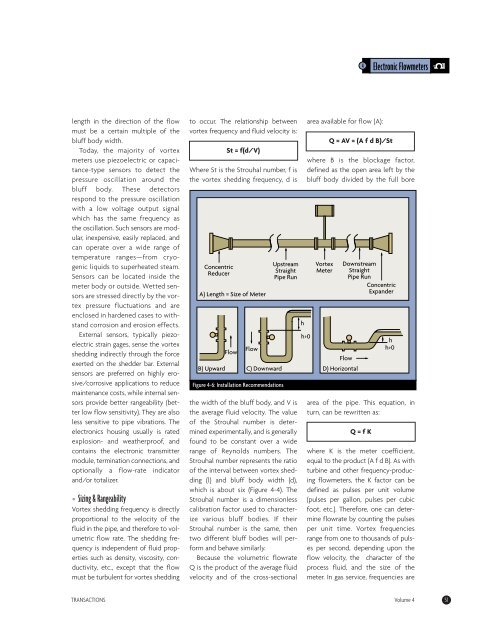
Concentric<br />
Reducer<br />
A) Length = Size of Meter<br />
Flow<br />
Flow<br />
Figure 4-6: Installation Recommendations<br />
Upstream<br />
Straight<br />
Pipe Run<br />
the width of the bluff body, <strong>and</strong> V is<br />
the average fluid velocity. The value<br />
of the Strouhal number is determined<br />
experimentally, <strong>and</strong> is generally<br />
found to be constant over a wide<br />
range of Reynolds numbers. The<br />
Strouhal number represents the ratio<br />
of the interval between vortex shedding<br />
(l) <strong>and</strong> bluff body width (d),<br />
which is about six (Figure 4-4). The<br />
Strouhal number is a dimensionless<br />
calibration factor used to characterize<br />
various bluff bodies. If their<br />
Strouhal number is the same, then<br />
two different bluff bodies will perform<br />
<strong>and</strong> behave similarly.<br />
Because the volumetric <strong>flow</strong>rate<br />
Q is the product of the average fluid<br />
velocity <strong>and</strong> of the cross-sectional<br />
area available for <strong>flow</strong> (A):<br />
B) Upward C) Downward D) Horizontal<br />
Q = AV = (A f d B)/St<br />
where B is the blockage factor,<br />
defined as the open area left by the<br />
bluff body divided by the full bore<br />
area of the pipe. This equation, in<br />
turn, can be rewritten as:<br />
Q = f K<br />
4 Electronic Flowmeters<br />
where K is the meter coefficient,<br />
equal to the product (A f d B). As with<br />
turbine <strong>and</strong> other frequency-producing<br />
<strong>flow</strong>meters, the K factor can be<br />
defined as pulses per unit volume<br />
(pulses per gallon, pulses per cubic<br />
foot, etc.). Therefore, one can determine<br />
<strong>flow</strong>rate by counting the pulses<br />
per unit time. Vortex frequencies<br />
range from one to thous<strong>and</strong>s of pulses<br />
per second, depending upon the<br />
<strong>flow</strong> velocity, the character of the<br />
process fluid, <strong>and</strong> the size of the<br />
meter. In gas service, frequencies are<br />
TRANSACTIONS Volume 4 51<br />
h<br />
h>0<br />
Vortex<br />
Meter<br />
Downstream<br />
Straight<br />
Pipe Run<br />
Concentric<br />
Exp<strong>and</strong>er<br />
Flow<br />
h<br />
h>0


