1 Clogging in Continuous Casting Nozzles K. G. Rackers and B. G. ...
1 Clogging in Continuous Casting Nozzles K. G. Rackers and B. G. ...
1 Clogging in Continuous Casting Nozzles K. G. Rackers and B. G. ...

You also want an ePaper? Increase the reach of your titles
YUMPU automatically turns print PDFs into web optimized ePapers that Google loves.
<strong>Rackers</strong>, K., <strong>and</strong> B.G. Thomas. 78th Steelmak<strong>in</strong>g Conference Proceed<strong>in</strong>gs, Nashville, TN, April 2, 1995, Iron <strong>and</strong> Steel<br />
Society, Warrendale, PA, Vol. 78, 1995, pp. 723-734.<br />
<strong>Clogg<strong>in</strong>g</strong> <strong>in</strong> Cont<strong>in</strong>uous Cast<strong>in</strong>g <strong>Nozzles</strong><br />
K. G. <strong>Rackers</strong> <strong>and</strong> B. G. Thomas<br />
Department of Mechanical <strong>and</strong> Industrial Eng<strong>in</strong>eer<strong>in</strong>g<br />
University of Ill<strong>in</strong>ois<br />
1206 West Green Street<br />
Urbana, IL 61801<br />
1<br />
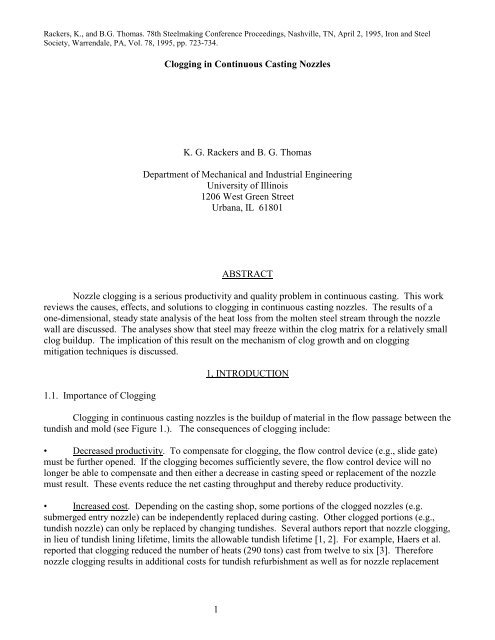
ABSTRACT<br />
Nozzle clogg<strong>in</strong>g is a serious productivity <strong>and</strong> quality problem <strong>in</strong> cont<strong>in</strong>uous cast<strong>in</strong>g. This work<br />
reviews the causes, effects, <strong>and</strong> solutions to clogg<strong>in</strong>g <strong>in</strong> cont<strong>in</strong>uous cast<strong>in</strong>g nozzles. The results of a<br />
one-dimensional, steady state analysis of the heat loss from the molten steel stream through the nozzle<br />
wall are discussed. The analyses show that steel may freeze with<strong>in</strong> the clog matrix for a relatively small<br />
clog buildup. The implication of this result on the mechanism of clog growth <strong>and</strong> on clogg<strong>in</strong>g<br />
mitigation techniques is discussed.<br />
1.1. Importance of <strong>Clogg<strong>in</strong>g</strong><br />
1, INTRODUCTION<br />
<strong>Clogg<strong>in</strong>g</strong> <strong>in</strong> cont<strong>in</strong>uous cast<strong>in</strong>g nozzles is the buildup of material <strong>in</strong> the flow passage between the<br />
tundish <strong>and</strong> mold (see Figure 1.). The consequences of clogg<strong>in</strong>g <strong>in</strong>clude:<br />
• Decreased productivity. To compensate for clogg<strong>in</strong>g, the flow control device (e.g., slide gate)<br />
must be further opened. If the clogg<strong>in</strong>g becomes sufficiently severe, the flow control device will no<br />
longer be able to compensate <strong>and</strong> then either a decrease <strong>in</strong> cast<strong>in</strong>g speed or replacement of the nozzle<br />
must result. These events reduce the net cast<strong>in</strong>g throughput <strong>and</strong> thereby reduce productivity.<br />
Increased cost . Depend<strong>in</strong>g on the cast<strong>in</strong>g shop, some portions of the clogged nozzles (e.g.<br />
submerged entry nozzle) can be <strong>in</strong>dependently replaced dur<strong>in</strong>g cast<strong>in</strong>g. Other clogged portions (e.g.,<br />
tundish nozzle) can only be replaced by chang<strong>in</strong>g tundishes. Several authors report that nozzle clogg<strong>in</strong>g,<br />
<strong>in</strong> lieu of tundish l<strong>in</strong><strong>in</strong>g lifetime, limits the allowable tundish lifetime [1, 2]. For example, Haers et al.<br />
reported that clogg<strong>in</strong>g reduced the number of heats (290 tons) cast from twelve to six [3]. Therefore<br />
nozzle clogg<strong>in</strong>g results <strong>in</strong> additional costs for tundish refurbishment as well as for nozzle replacement
Decreased quality . Nonmetallic particles can become dislodged from the clog buildup <strong>and</strong> result<br />
<strong>in</strong> unacceptable cleanl<strong>in</strong>ess defects <strong>in</strong> the product, especially <strong>in</strong> deep drawn applications requir<strong>in</strong>g oxides<br />
be smaller than fifty microns <strong>in</strong> diameter [4 - 11]. The restriction of the flow passage may also cause<br />
undesirable flow patterns <strong>in</strong> the mold which thereby cause quality problems (e.g., mold flux <strong>in</strong>gestion,<br />
shell th<strong>in</strong>n<strong>in</strong>g) [6, 12 - 14]. Also, the mold level transients occurr<strong>in</strong>g when a tundish is replaced due to<br />
tundish nozzle clogg<strong>in</strong>g, can cause reduced quality [3].<br />
1.2. Types of Clogs<br />
There are four general types of clogg<strong>in</strong>g, each from a different orig<strong>in</strong>. In practice, clogg<strong>in</strong>g<br />
with<strong>in</strong> a s<strong>in</strong>gle nozzle could be due to a comb<strong>in</strong>ation of two or more types. The classification chosen<br />
here dist<strong>in</strong>guishes between clogs consist<strong>in</strong>g of deoxidation products, solidified steel, complex oxides,<br />
<strong>and</strong> reaction products.<br />
1.2.1. Agglomeration of Deoxidation Products - Buildups consist<strong>in</strong>g of deoxidation products<br />
(e.g., alum<strong>in</strong>a, titania, zirconia) have been observed <strong>in</strong> the nozzles. These deoxidation products are of<br />
the same composition <strong>and</strong> size (typically 1 - 20 micron [10, 15 - 17]) as is found <strong>in</strong> the mold [10, 16].<br />
The deoxidation products s<strong>in</strong>ter together to form a network [18 - 20, 16].<br />
This s<strong>in</strong>tered matrix may or may not encompass steel. Steel has been found with<strong>in</strong> the matrix for<br />
heats with low residual deoxidation product content, as might be found when us<strong>in</strong>g DH degass<strong>in</strong>g or for<br />
high carbon concentrations [10, 14]. No steel is found with<strong>in</strong> the matrix when the deoxidation product<br />
concentration is high, as might be found when us<strong>in</strong>g argon bubbl<strong>in</strong>g dur<strong>in</strong>g secondary ref<strong>in</strong><strong>in</strong>g <strong>and</strong> low<br />
carbon concentrations (e.g. less than 0.10% C) [10, 14].<br />
1.2.2. Solid Steel Buildup - If the superheat is low, <strong>and</strong> the heat transfer from the stream is high,<br />
the steel may freeze with<strong>in</strong> the nozzle. This is especially true at the start of cast if nozzle preheat is<br />
<strong>in</strong>adequate [21].<br />
1.2.3. Agglomeration of Complex Oxides - Clogs conta<strong>in</strong><strong>in</strong>g nonmetallic materials not result<strong>in</strong>g<br />
from deoxidation have also been observed. Clogs have been observed <strong>in</strong> the submerged entry nozzle<br />
port area which have a chemistry <strong>in</strong>dicative of a comb<strong>in</strong>ation of mold flux <strong>and</strong> deoxidation particles.<br />
Here it is believed that the mold flux is drawn <strong>in</strong>to the<br />
top of the ports due to the recirculation flow pattern <strong>in</strong> the upper part of the mold <strong>and</strong> due to the<br />
tendency of the flux to coat the nozzle [14, 22]. Once <strong>in</strong>side the nozzle, the flux assimilates deoxidation<br />
particles, thereby <strong>in</strong>creas<strong>in</strong>g the clog volume [6].<br />
Clogs conta<strong>in</strong><strong>in</strong>g calcium alum<strong>in</strong>ates or calcium sulfides have also been observed on calcium<br />
treated heats [5, 11, 15, 23 - 25]. The effect of calcium on clogg<strong>in</strong>g will be discussed later <strong>in</strong> reference<br />
to clogg<strong>in</strong>g mitigation efforts.<br />
1.2.4. Reaction Product Buildup - <strong>Clogg<strong>in</strong>g</strong> with the composition of deoxidation products but<br />
deposited <strong>in</strong> a film <strong>in</strong>stead of a s<strong>in</strong>tered network of particles has been observed. The source for these<br />
buildups has been attributed to reactions between the deoxidant <strong>and</strong> 1) air drawn <strong>in</strong>to the nozzle due to<br />
the negative gauge pressure <strong>and</strong> the porosity of the nozzle [19, 26], 2) oxygen evolved from the steel due<br />
to the lower steel temperature adjacent to the nozzle [27], <strong>and</strong> 3) oxygen generated by silica refractory<br />
2
decomposition [18, 19, 26, 28, 29]. These mechanisms are consistent with the reported observations of<br />
<strong>in</strong>creased clogg<strong>in</strong>g as soluble alum<strong>in</strong>um concentration is <strong>in</strong>creased [4, 30].<br />
1.3. Causes of <strong>Clogg<strong>in</strong>g</strong><br />
For those clogs consist<strong>in</strong>g of solidified steel or reaction products, the transport <strong>and</strong> attachment<br />
mechanism are straightforward because the clogg<strong>in</strong>g phenomenon takes place at the nozzle wall. But for<br />
clogs conta<strong>in</strong><strong>in</strong>g deoxidation products, the process of their transport <strong>and</strong> attachment is more<br />
complicated.<br />
1.3.1. Transport of Deoxidation Products to the Nozzle Wall - Several theories have been<br />
proposed concern<strong>in</strong>g flow patterns <strong>and</strong> geometries which enhance transport of deoxidation products to<br />
the nozzle wall:<br />
Turbulent Recirculation Zones . With<strong>in</strong> a recirculation zone, turbulent velocity fluctuations<br />
oriented <strong>in</strong> all directions are present. Those fluctuations toward the wall will enable deposition [31].<br />
Turbulent Flow . Turbulent eddies, even <strong>in</strong> the absence of a recirculation zone, will transport<br />
deoxidation products to the nozzle wall [17].<br />
Rough Nozzle Walls . As the roughness of the nozzle wall is <strong>in</strong>creased (e.g., due to irregular<br />
buildup or erosion) the probability of <strong>in</strong>terception of entra<strong>in</strong>ed deoxidation particles <strong>in</strong>creases [11, 31,<br />
32].<br />
External Corners . S<strong>in</strong>ce the density of alum<strong>in</strong>a is less than steel, alum<strong>in</strong>a will tend to be driven<br />
toward the wall for flow around an external corner (e.g., tundish nozzle entry). This driv<strong>in</strong>g force is<br />
expected to be significant only for large alum<strong>in</strong>a particles (e.g., 36 micron [17]).<br />
1.3.2. Attachment of Deoxidation Products to the Nozzle Wall - Deoxidation particles are<br />
attached to the nozzle wall by surface tension <strong>and</strong>, after sufficient time, by s<strong>in</strong>tered bonds. The surface<br />
tension of the steel creates a void <strong>and</strong>, consequently, an attractive force between the deoxidation product<br />
<strong>and</strong> the wall (or another deoxidation product) [10, 33]. The magnitude of this force for the case of a 2.5<br />
micron deoxidation product attach<strong>in</strong>g to a ceramic filter has been calculated to be approximately an<br />
order of magnitude greater than the drag <strong>and</strong> buoyant forces on the particle [20].<br />
The s<strong>in</strong>tered bond between the particle <strong>and</strong> wall (or another particle) forms relatively rapidly at<br />
these temperatures (e.g., only 0.03 seconds is required for two ten micron particles to develop a<br />
sufficient neck between them to withst<strong>and</strong> drag <strong>and</strong> buoyant forces [20]).<br />
1.4. Ways to Avoid <strong>Clogg<strong>in</strong>g</strong><br />
The most obvious means to reduce clogg<strong>in</strong>g is to decrease the concentration of deoxidation<br />
products <strong>and</strong> the formation of reoxidation products [4, 10, 14, 23, 34, 35]. Means to achieve this<br />
<strong>in</strong>crease <strong>in</strong> steel cleanl<strong>in</strong>ess have been reviewed by Byrne et al. <strong>and</strong> Szekeres [6, 14]. The important<br />
aspects of clean steelmak<strong>in</strong>g <strong>in</strong>clude:<br />
3
Ladle Ref<strong>in</strong><strong>in</strong>g Practice . A vacuum degass<strong>in</strong>g treatment yields better cleanl<strong>in</strong>ess than does argon<br />
bubbl<strong>in</strong>g [36].<br />
Reoxidation Prevention . Submerged ladle-to-tundish pour<strong>in</strong>g, shielded tundish surface, <strong>and</strong><br />
leak-tight refractory jo<strong>in</strong>ts will reduce exposure of the steel to oxygen <strong>and</strong> thereby improve cleanl<strong>in</strong>ess<br />
[14].<br />
Deoxidation Product Removal. Optimal tundish flow patterns [37] as well as filtration [20, 33,<br />
38] <strong>and</strong> electromagnetic techniques [39] can remove deoxidation products from the melt.<br />
Flux Entra<strong>in</strong>ment Prevention . Submerged ladle-to-tundish pour<strong>in</strong>g <strong>and</strong> avoidance of ladle slag<br />
carryover will reduce the amount of exogenous <strong>in</strong>clusions <strong>in</strong> the melt [6, 14].<br />
It is unlikely that steel cleanl<strong>in</strong>ess improvements will completely elim<strong>in</strong>ate nozzle clogg<strong>in</strong>g.<br />
Dawson calculated that for typical cast<strong>in</strong>g conditions, nozzle blockage could occur if as little as one <strong>in</strong><br />
every 1500 nonmetallic <strong>in</strong>clusions were deposited on the nozzle [31]. To reduce the deposition of the<br />
entra<strong>in</strong>ed deoxidation products, several techniques have been utilized as discussed below.<br />
1.4.1. Argon Injection - Argon <strong>in</strong>jected through the nozzle wall or stopper rod <strong>in</strong>to the steel<br />
stream is widely employed to reduce nozzle clogg<strong>in</strong>g. A typical <strong>in</strong>jection rate is 5 five liter/m<strong>in</strong>ute<br />
(STP) [27, 40]. Several reasons have been suggested for the improved clogg<strong>in</strong>g resistance:<br />
A film of argon is formed on the nozzle wa ll which prevents the deoxidation product from<br />
contact<strong>in</strong>g the wall [41, 42, 43].<br />
The argon bubbles flush the deoxidation products off the nozzle [43].<br />
The argon bubbles promote the flota tion of deoxidation products [19].<br />
Argon <strong>in</strong>jection <strong>in</strong>creases the turbulence <strong>and</strong> thereb y causes the deposit to be flushed off [35]. It<br />
is noted that this mechanism contradicts a previously mentioned hypothesis which states that turbulence<br />
enhances deposition.<br />
The pressure <strong>in</strong>side the nozzle is <strong>in</strong>creased which thereby reduces air aspiration through the<br />
nozzle [14, 43, 44]. In the absence of argon <strong>in</strong>jection, negative gauge pressure has been measured <strong>in</strong><br />
water models near the slide gate <strong>and</strong> the stopper rod seat<strong>in</strong>g surface [43].<br />
The argon prevents a chemical reaction between the steel <strong>and</strong> the refractory [19].<br />
The argon can be <strong>in</strong>jected through the pores <strong>in</strong> the refractory material [1, 2, 18, 41, 42, 44] or via<br />
mach<strong>in</strong>ed or laser cut holes <strong>in</strong> the refractory [7, 18, 19]. Tailor<strong>in</strong>g the argon flow to be greater <strong>in</strong> areas<br />
of high deposition [18, 44] <strong>and</strong> to be locally uniform [2, 44] has been shown to reduce clogg<strong>in</strong>g.<br />
Disadvantages of argon <strong>in</strong>jection <strong>in</strong>clude <strong>in</strong>creased quality defects <strong>and</strong> nozzle slag l<strong>in</strong>e erosion<br />
due to the <strong>in</strong>creased mold level fluctuations [14, 27], bubble entrapment by the shell [8, 14, 44], <strong>and</strong><br />
nozzle crack<strong>in</strong>g due to high back pressure or decreased nozzle thermal shock resistance [1, 18, 44]. It is<br />
also suspected that argon <strong>in</strong>jection tends to move the clogg<strong>in</strong>g problem to a different location [32].<br />
4
1.4.2. Calcium Treatment - Alum<strong>in</strong>a clogg<strong>in</strong>g can be reduced by add<strong>in</strong>g calcium to the steel to<br />
prevent the formation of solid alum<strong>in</strong>a [30, 45, 25, 46]. As shown <strong>in</strong> Figure 2, for a typical melt<br />
temperature of 1550˚ C, liquid is the equilibrium pha se for calcia-alum<strong>in</strong>a mixtures conta<strong>in</strong><strong>in</strong>g 40 - 60%<br />
alum<strong>in</strong>a. Furthermore, it is believed that under steelmak<strong>in</strong>g conditions, mixtures conta<strong>in</strong><strong>in</strong>g a higher<br />
fraction of alum<strong>in</strong>a will be also be liquid. This is based on the observation that when CaO·2Al2O3<br />
<strong>in</strong>clusions (79% alum<strong>in</strong>a) are found <strong>in</strong> the f<strong>in</strong>al cast product, these <strong>in</strong>clusions take a spherical form <strong>and</strong><br />
the nozzle experiences much less clogg<strong>in</strong>g [24].<br />
The disadvantages of calcium treatment <strong>in</strong>clude:<br />
Increased clogg<strong>in</strong>g relative to the non-treated c ondition if <strong>in</strong>sufficient calcium is added, due to<br />
the formation of CaO·6Al2O3 [17, 24, 25].<br />
Erosion of refractories [5, 14, 27].<br />
Also, calcium treatment will not work for high sulfur steels because calcium will react with<br />
sulfur to form solid calcium sulfide <strong>in</strong>stead of liquefy<strong>in</strong>g the alum<strong>in</strong>a [11] (e.g., sulfur must be less than<br />
0.007% for a typical total alum<strong>in</strong>um concentration of 0.04% [47]). However, it has been proposed that<br />
calcium treatment might still be successful if the sulfur is added after calcium treatment [32].<br />
1.4.3. Nozzle Material Modifications - A variety of nozzle compositions have been <strong>in</strong>vestigated.<br />
Calcia additions to the nozzle [10, 48, 49, 50] have yielded decreased clogg<strong>in</strong>g by liquefy<strong>in</strong>g the<br />
<strong>in</strong>clusions, as discussed above. The effectiveness of this method is limited by the diffusion of the calcia<br />
to the refractory surface [50].<br />
Other compositions <strong>and</strong> coat<strong>in</strong>gs have also been attempted [1, 3, 29, 32, 40, 51, 52, 53], but the<br />
cause for the decreased clogg<strong>in</strong>g is uncerta<strong>in</strong>. For example, the addition of boron nitride has been shown<br />
to markedly reduce clogg<strong>in</strong>g [29, 32, 40]. However, it is not known whether the beneficial effect of<br />
boron nitride is due to the formation of a liquid boron oxide film [29], decreased surface roughness [31],<br />
or another cause. Other possible explanations for the observed clogg<strong>in</strong>g reduction of the various<br />
materials <strong>in</strong>vestigated are decreased thermal conductivity [51, 52, 53], decreased contact angle with steel<br />
[29, 51, 52], reduced reactivity with steel [26], <strong>and</strong> decreased air aspiration [3].<br />
1.4.4. Nozzle Geometry Modifications - In an effort to reduce the effect of clogg<strong>in</strong>g, oversized<br />
nozzle bores [3, 54] <strong>and</strong> replaceable submerged entry nozzles [3] are widely employed. To reduce the<br />
degree of clogg<strong>in</strong>g, the follow<strong>in</strong>g have been <strong>in</strong>vestigated:<br />
Improved jo<strong>in</strong>t seal<strong>in</strong>g. Strengthen<strong>in</strong>g the steel work that holds the nozzle <strong>in</strong> place was found to<br />
reduce air aspiration <strong>and</strong> thereby reduce clogg<strong>in</strong>g [18].<br />
Rounded nozzle entrance. Incorporat<strong>in</strong>g a rounde d entrance (<strong>in</strong> lieu of a sharp corner) to the<br />
tundish nozzle <strong>and</strong> ensur<strong>in</strong>g proper vertical alignment can reduce clogg<strong>in</strong>g at the nozzle entrance by<br />
elim<strong>in</strong>at<strong>in</strong>g separated flow [31].<br />
5
Internal step. A five millimeter annular step <strong>in</strong>corporated at the mid-height of the submerged<br />
entry nozzle has been found to decrease alum<strong>in</strong>a buildup <strong>in</strong> the lower part of the nozzle as well as<br />
decreas<strong>in</strong>g flow imp<strong>in</strong>gement on the mold wide face [55].<br />
Vary<strong>in</strong>g nozzle <strong>in</strong>ternal diameter. Increas<strong>in</strong>g th e nozzle <strong>in</strong>ternal diameter just below the stopper<br />
rod seat<strong>in</strong>g surface has reduced clogg<strong>in</strong>g [14, 56].<br />
Flat bottomed nozzle. Decreased port clogg<strong>in</strong>g was observed when the elevation of the nozzle<br />
<strong>in</strong>ternal bottom <strong>and</strong> port bottom were co<strong>in</strong>cident (i.e., no nozzle well) [55].<br />
Insulation around nozzle. Insulation, as well as preheat <strong>and</strong> heat<strong>in</strong>g, around the clogg<strong>in</strong>g location<br />
may reduce clogg<strong>in</strong>g [14].<br />
2, INITIAL MODELING EFFORTS<br />
The first steps we took to underst<strong>and</strong> nozzle clogg<strong>in</strong>g were to develop simple models of the<br />
various aspects of the clogg<strong>in</strong>g process. Described below are models which predict the strength of the<br />
clog buildup <strong>and</strong> the role of heat transfer <strong>in</strong> re<strong>in</strong>forc<strong>in</strong>g the clog buildup. In addition, the relationship<br />
between slide gate position <strong>and</strong> degree of clogg<strong>in</strong>g, the effect of clogg<strong>in</strong>g on air aspiration, the<br />
deposition rate of deoxidation products, <strong>and</strong> the role of reoxidation <strong>in</strong> clogg<strong>in</strong>g are discussed.<br />
2.1. Strength of the Clog<br />
The clog matrix has been described as a powdery friable buildup that could be easily removed by<br />
the touch of a f<strong>in</strong>ger [16]. To expla<strong>in</strong> the ability of this buildup to withst<strong>and</strong> erosion by the molten steel,<br />
Duderstadt [68] proposed that the clog was strengthened by solid steel dendrites which grew radially<br />
<strong>in</strong>ward due to heat loss through the nozzle wall. However, essentially pure alum<strong>in</strong>a buildups have been<br />
observed <strong>in</strong> practice [4, 10]. Furthermore, Ogibayashi et al. [10] claimed that the steel with<strong>in</strong> the clog<br />
matrix is liquid dur<strong>in</strong>g cast<strong>in</strong>g as evidenced by the observation of pure alum<strong>in</strong>a clogg<strong>in</strong>g <strong>and</strong> alum<strong>in</strong>a<br />
clogg<strong>in</strong>g with entrapped steel both appear<strong>in</strong>g <strong>in</strong> the same<br />
region. As mentioned above, Ogibayashi et al. concluded that the presence of pure alum<strong>in</strong>a or alum<strong>in</strong>a<br />
embedded <strong>in</strong> steel will be determ<strong>in</strong>ed by the steel cleanl<strong>in</strong>ess (i.e., concentration of alum<strong>in</strong>a <strong>in</strong> the steel).<br />
Two questions that are prompted by the above observations are:<br />
1) How dense must a clog matrix be to withst<strong>and</strong> erosion?<br />
2) How can steel cleanl<strong>in</strong>ess determ<strong>in</strong>e the clog morphology? In other words, if clog growth is<br />
envisioned as the entrapment of entra<strong>in</strong>ed deoxidation products by the clog matrix, then how does the<br />
rate at which the deoxidation products are entrapped (which will clearly be a function of concentration)<br />
affect where the deoxidation products are entrapped? In fact, s<strong>in</strong>ce the ejection of the steel from<br />
between the deposited deoxidation products [10] requires f<strong>in</strong>ite time, one might expect that the dirtier<br />
the steel the greater the amount of steel entrapped with<strong>in</strong> the clog.<br />
Simplified models to address these issues were developed <strong>and</strong> are discussed below:<br />
6
2.1.1. Erosion of an Alum<strong>in</strong>a Buildup - The simplest model developed was that of a s<strong>in</strong>gle<br />
“f<strong>in</strong>ger” of alum<strong>in</strong>a protrud<strong>in</strong>g radially <strong>in</strong>to the bulk flow. If I restrict my attention to areas with a<br />
uniform mean flow (e.g., ignore boundary layers <strong>and</strong> separation zones), I can treat this as an alum<strong>in</strong>a rod<br />
subjected to a distributed load result<strong>in</strong>g from the drag force imposed by the molten steel flow (Figure 3).<br />
Assum<strong>in</strong>g a bulk flow of 1.6 m/s (corresponds to 3 ton/m<strong>in</strong> through a 76 mm diameter nozzle<br />
bore), alum<strong>in</strong>a failure stress of 300 MPa [20], <strong>and</strong> drag correspond<strong>in</strong>g to flow past a cyl<strong>in</strong>der; the<br />
maximum length of a 10 micron diameter rod would be 0.5 mm (i.e. at this length the outer fiber<br />
bend<strong>in</strong>g stress would exceed the failure stress). Clearly, even if the <strong>in</strong>clusions were completely s<strong>in</strong>tered<br />
together, the buildup must be greater than one <strong>in</strong>clusion <strong>in</strong> diameter to reach the extent of clogs observed<br />
<strong>in</strong> practice. For the buildup to extend 20 mm radially <strong>in</strong>to the bore, the alum<strong>in</strong>a rod must be 0.26 mm <strong>in</strong><br />
diameter.<br />
The “pure” alum<strong>in</strong>a clogs observed <strong>in</strong> practice will still have significant spac<strong>in</strong>g between the<br />
deposited particles. Therefore, the buildup must be thicker than the value predicted above to offset the<br />
reduction <strong>in</strong> effective strength. The above model was modified to account for a buildup conta<strong>in</strong><strong>in</strong>g a<br />
volume fraction of 17% alum<strong>in</strong>a (based on surface tension arguments as discussed below). For this<br />
porous buildup to extend 20 mm radially <strong>in</strong>to the bore, the alum<strong>in</strong>a rod must be 0.62 mm <strong>in</strong> diameter.<br />
Note that <strong>in</strong> both cases, buildups of significant length will survive if the buildup is only a fraction<br />
of a millimeter wide. If the deposition process is considered as the addition of deoxidation particles to<br />
r<strong>and</strong>om locations on a clog matrix, then it can be concluded that only a fraction of the buildup f<strong>in</strong>gers<br />
will have sufficient cross-sectional area to cont<strong>in</strong>ue grow<strong>in</strong>g. It also follows that the fraction of the<br />
buildup f<strong>in</strong>gers that cont<strong>in</strong>ue to grow will be greater if their unsupported length is decreased by<br />
solidified steel.<br />
2.1.2. Steel Re<strong>in</strong>forcement of the Alum<strong>in</strong>a Matrix - To determ<strong>in</strong>e whether the steel with<strong>in</strong> the<br />
matrix solidifies dur<strong>in</strong>g cast<strong>in</strong>g, a one dimensional, steady state heat transfer model of the submerged<br />
entry nozzle was developed (Figure 4). The Sleicher <strong>and</strong> Rouse correlation [57] was used to predict the<br />
heat loss from the molten steel stream. Heat transfer through the clog <strong>and</strong> nozzle wall was assumed to<br />
be via conduction only. Heat was lost to ambient by radiation. The dimensions, material properties, <strong>and</strong><br />
cast<strong>in</strong>g conditions considered are shown <strong>in</strong> Table I.<br />
For a sufficiently large clog thickness, the entrapped steel adjacent to the wall will freeze. The<br />
effect of clog thickness on the frozen steel (i.e., skull) thickness is shown <strong>in</strong> Figure 5. It is seen that for<br />
clog thicknesses greater than 3.5 mm, skull<strong>in</strong>g will occur. The effect of vary<strong>in</strong>g the assumed parameters<br />
(see Table I) on the skull<strong>in</strong>g behavior can be seen <strong>in</strong> Figure 6. It is seen that the conductivity of the<br />
refractory <strong>and</strong> the freez<strong>in</strong>g temperature of the steel have a large effect on the degree of skull<strong>in</strong>g.<br />
The freez<strong>in</strong>g temperature will be a function of the concentration of solute at the <strong>in</strong>terface. To<br />
estimate the solute concentration at the <strong>in</strong>terface, a transient solidification analysis was accomplished<br />
(see Figure 7). The concentration profile ahead of the <strong>in</strong>terface was approximated as the profile which<br />
would result from a constant <strong>in</strong>terface velocity <strong>and</strong> a quiescent melt. Latent heat evolution was<br />
accounted for <strong>and</strong> sensible heat loss was neglected. An explicit time stepp<strong>in</strong>g algorithm was used to<br />
track the <strong>in</strong>terface position.<br />
7
As shown <strong>in</strong> Figure 8, the constant growth rate assumption is consistent with the predicted<br />
solution after the <strong>in</strong>itial transient. However, solute convection is expected to be non-negligible for low<br />
growth rates (e.g., for an <strong>in</strong>terface velocity of 5 mm/hr, the concentration boundary layer thickness =<br />
D/V = 14 mm). This will tend to <strong>in</strong>crease the growth rate from the predicted values. Consider<strong>in</strong>g only<br />
superheat removal, the sensible heat loss is negligible compared to the latent heat loss (i.e., Stefan # =<br />
.07).<br />
The net results of the transient analysis are shown <strong>in</strong> Figure 9. It is seen that as the clogg<strong>in</strong>g rate<br />
<strong>in</strong>creases, the distance between the clog front <strong>and</strong> the solidification front <strong>in</strong>creases (e.g., for a f<strong>in</strong>al clog<br />
thickness of 20 mm, <strong>in</strong>creas<strong>in</strong>g the deposition rate from 1 to 20 mm/hr decreases the f<strong>in</strong>al skull thickness<br />
by 4 mm). The “steady state prediction” curve shows the predicted steady state skull thickness us<strong>in</strong>g the<br />
<strong>in</strong>terface temperature obta<strong>in</strong>ed from the transient analysis. By compar<strong>in</strong>g the two curves, it is seen that<br />
the skulls are approximately at the steady state temperature distribution.<br />
A steady state analysis of the tundish nozzle was also accomplished. The steady state submerged<br />
entry nozzle model was modified to <strong>in</strong>clude an additional steel shell outside of the nozzle (to represent<br />
the mount<strong>in</strong>g block) <strong>and</strong> an <strong>in</strong>terven<strong>in</strong>g gap (Figure 10). The additional parameters are shown <strong>in</strong> Table<br />
I. As seen <strong>in</strong> Figure 11, <strong>in</strong> spite of the <strong>in</strong>creased thermal resistance, skull<strong>in</strong>g is still observed when the<br />
clog thickness is greater than 4 mm. The reason that the <strong>in</strong>crease <strong>in</strong> thermal resistance has such a small<br />
effect on the skull<strong>in</strong>g behavior is that the heat transfer area between the nozzle assembly <strong>and</strong> ambient<br />
also <strong>in</strong>creases. Figure 12 shows that <strong>in</strong>creas<strong>in</strong>g the mount<strong>in</strong>g block thickness from 100 mm to 300 mm<br />
will actually result <strong>in</strong> a small <strong>in</strong>crease <strong>in</strong> skull thickness.<br />
These analyses <strong>in</strong>dicate that skull<strong>in</strong>g may be an <strong>in</strong>tegral part of the clogg<strong>in</strong>g mechanism <strong>in</strong> some<br />
regions. Skull<strong>in</strong>g would enable <strong>in</strong>clusion deposits of smaller width to survive by reduc<strong>in</strong>g their<br />
unsupported length. S<strong>in</strong>ce this would reduce re-entra<strong>in</strong>ment of the clog matrix by the molten steel<br />
stream, it would <strong>in</strong>crease the clogg<strong>in</strong>g rate.<br />
Also, skull<strong>in</strong>g may help expla<strong>in</strong> how steel cleanl<strong>in</strong>ess effects the quantity of entrapped steel <strong>in</strong><br />
the clog. As the cleanl<strong>in</strong>ess is degraded, the deoxidation product deposition rate will <strong>in</strong>crease, thereby<br />
caus<strong>in</strong>g the distance between the solidification front <strong>and</strong> the clog front to <strong>in</strong>crease. This will enable the<br />
clog matrix, which acts like a filter, to capture more deoxidation products <strong>and</strong> expel liquid steel.<br />
Furthermore, the density of the buildup will be necessarily higher to prevent failure of the longer<br />
unsupported buildup length. If the volume fraction of alum<strong>in</strong>a with<strong>in</strong> the matrix becomes high enough,<br />
then all the steel with<strong>in</strong> that region of the clog will be expelled [20].<br />
The effect of skull<strong>in</strong>g on clog growth will be greater dur<strong>in</strong>g some cast<strong>in</strong>g transients (e.g.,<br />
<strong>in</strong>itiation <strong>and</strong> <strong>in</strong>terruption of cast<strong>in</strong>g) due to low nozzle or melt temperature. Dur<strong>in</strong>g these transients,<br />
skull<strong>in</strong>g will not only <strong>in</strong>crease the strength of the clog matrix, but may outpace the clog front <strong>and</strong> extend<br />
<strong>in</strong>to the bulk flow. This might be especially important at <strong>in</strong>itiation of cast<strong>in</strong>g s<strong>in</strong>ce it would <strong>in</strong>crease the<br />
effective wall roughness <strong>and</strong> therefore <strong>in</strong>crease deoxidation product capture. Whether skull<strong>in</strong>g occurs<br />
dur<strong>in</strong>g steady state or transient cast<strong>in</strong>g conditions, the rate of its remelt<strong>in</strong>g (if the temperature is<br />
subsequently <strong>in</strong>creased) will be limited by the rate of carbon diffusion to the <strong>in</strong>terface.<br />
2.2. Other Model<strong>in</strong>g Results<br />
8
To determ<strong>in</strong>e the relative importance of various phenomena, a number of additional models were<br />
developed, as discussed below:<br />
2.2.1 Nozzle Flow Model - The only measure of clogg<strong>in</strong>g dur<strong>in</strong>g the cast is the slide gate or<br />
stopper rod position. A crude model of the tundish nozzle, slide gate, <strong>and</strong> submerged entry nozzle was<br />
developed to quantify the relationship between slide gate position <strong>and</strong> degree of clogg<strong>in</strong>g. The tundish<br />
nozzle <strong>and</strong> submerged entry nozzle were modeled as a rough pipe whose radius was decreased by an<br />
amount equal to the clog thickness. The nozzle ports were modeled as a tee. The slide gate was<br />
modeled as an orifice of equivalent cross section <strong>and</strong> subsequently adjusted to better match caster data.<br />
The pressure drop due to flow acceleration at the tundish nozzle entrance was determ<strong>in</strong>ed us<strong>in</strong>g<br />
Bernoulli’s equation. The cast<strong>in</strong>g conditions considered are given <strong>in</strong> Table II.<br />
Table II. Fluid Flow Analysis Parameters<br />
Parameter Value Source<br />
Density 7015 kg/m3 [62]<br />
Tundish Melt Height 1203 mm<br />
Nozzle Submergence Depth 203 mm<br />
Tundish Nozzle Length 343 mm<br />
Submerged Entry Nozzle 840 mm<br />
Length<br />
Nozzle Inner Diameter 80 mm<br />
Nozzle Surface Roughness 0.5 mm<br />
Port Resistance Coefficient 0.8 50 mm<br />
Dia. Tee<br />
[64]<br />
The relationship between degree of clogg<strong>in</strong>g <strong>and</strong> the slide gate position required to ma<strong>in</strong>ta<strong>in</strong> the<br />
cast<strong>in</strong>g rate is shown <strong>in</strong> Figure 13. It is seen that very little slide gate travel is required until the clog<br />
reaches a critical thickness. After reach<strong>in</strong>g the critical thickness, a small <strong>in</strong>crease <strong>in</strong> clog thickness<br />
necessitates a large change <strong>in</strong> slide gate position. The underly<strong>in</strong>g reason for this behavior is that for a<br />
fixed cast<strong>in</strong>g rate, the turbulent pressure drop through a rough pipe is <strong>in</strong>versely proportional to the fifth<br />
power of the pipe radius. This result <strong>in</strong>dicates that slide gate position is generally a poor <strong>in</strong>dicator of the<br />
extent of <strong>in</strong>itial clogg<strong>in</strong>g.<br />
This analysis was also utilized to predict conditions <strong>and</strong> regions at which air aspiration were<br />
most likely to occur. Figure 14 shows the gauge pressure with<strong>in</strong> the tundish <strong>and</strong> submerged entry<br />
nozzles for a cast<strong>in</strong>g speed of 4 ton/m<strong>in</strong> <strong>and</strong> three different clogg<strong>in</strong>g conditions.<br />
The first condition represents cast<strong>in</strong>g through a nozzle with no clogg<strong>in</strong>g. As expected, the<br />
majority of the pressure drop for this case is due to the slide gate. Note that the pressure <strong>in</strong> the upper<br />
half of the submerged entry nozzle is predicted to be below atmospheric pressure, mak<strong>in</strong>g this region<br />
susceptible to aspiration. These results are <strong>in</strong> good qualitative agreement with the measurements of<br />
Heaslip et. al. [43] who performed a series of water model<strong>in</strong>g experiments which quantified the effect of<br />
gas <strong>in</strong>jection on the pressure distribution. Additional work is planned to simulate the specific cast<strong>in</strong>g<br />
conditions he considered.<br />
9
The second condition considered represents a tundish <strong>and</strong> submerged entry nozzle with a limit<strong>in</strong>g<br />
amount of clogg<strong>in</strong>g (i.e., the required slide gate position to ma<strong>in</strong>ta<strong>in</strong> cast speed is 100%). It is noted<br />
here that the pressure everywhere rema<strong>in</strong>s above atmospheric. The f<strong>in</strong>al case considered represents<br />
limit<strong>in</strong>g clogg<strong>in</strong>g <strong>in</strong> the tundish nozzle <strong>and</strong> no clogg<strong>in</strong>g <strong>in</strong> the submerged entry nozzle (e.g., the<br />
condition after a submerged entry nozzle replacement). For this case the entire tundish nozzle is below<br />
atmospheric pressure.<br />
2.2.3. Fraction Alum<strong>in</strong>a Captured by Nozzle<br />
When no clogg<strong>in</strong>g countermeasures are employed, nozzle clogg<strong>in</strong>g has been observed to limit<br />
sequence cast<strong>in</strong>g to 1-3 heats [1, 45]. Assum<strong>in</strong>g 250 ton heats <strong>and</strong> a 30 ppm comb<strong>in</strong>ed oxygen<br />
concentration <strong>in</strong> the tundish, 32 kg of alum<strong>in</strong>a will pass through the nozzles <strong>in</strong> two heats.<br />
The density of a pure alum<strong>in</strong>a clog will depend on the pack<strong>in</strong>g efficiency of the deoxidation<br />
products. If the clog is modeled as a group of 10 micron diameter f<strong>in</strong>ger-like structures (see Figure 15)<br />
<strong>and</strong> the critical distance between the f<strong>in</strong>gers for ejection of molten steel is calculated [10], the volume<br />
fraction of alum<strong>in</strong>a <strong>in</strong> a “pure alum<strong>in</strong>a” clog is 17%. Consider<strong>in</strong>g a two str<strong>and</strong> caster [1] hav<strong>in</strong>g 1 m<br />
long nozzles with 20 mm thick clogs, the amount of alum<strong>in</strong>a with<strong>in</strong> the clogs is calculated to be 5.1 kg.<br />
Tak<strong>in</strong>g the ratio of the deposited alum<strong>in</strong>a to the alum<strong>in</strong>a throughput, it is seen that <strong>in</strong> these severe<br />
clogg<strong>in</strong>g situations about 16% of the alum<strong>in</strong>a pass<strong>in</strong>g through the nozzle is deposited (assum<strong>in</strong>g the clog<br />
is composed of deoxidation products). This <strong>in</strong>dicates that <strong>in</strong> the absence of clogg<strong>in</strong>g countermeasures<br />
(e.g., argon <strong>in</strong>jection), transport of the <strong>in</strong>clusions to the nozzle wall is fairly efficient.<br />
2.2.4. Relationship between Reoxidation <strong>and</strong> <strong>Clogg<strong>in</strong>g</strong> Rate<br />
Nitrogen pickup between the tundish <strong>and</strong> mold can be used to quantify the reoxidation occurr<strong>in</strong>g<br />
<strong>in</strong> the nozzle [58]. Prior to efforts to improve nozzle air-tightness, McPherson [58] measured nitrogen<br />
pickup values of 5 ppm. Consider<strong>in</strong>g 250 ton heats <strong>and</strong> assum<strong>in</strong>g all the aspirated oxygen forms<br />
alum<strong>in</strong>a, this reoxidation source would generate 1.4 kg of alum<strong>in</strong>a <strong>in</strong> two heats, a substantial fraction of<br />
the above calculated clog mass.<br />
The aspirated oxygen also accelerates the deposition of deoxidation products by creat<strong>in</strong>g a<br />
surface tension gradient around the deoxidation product which <strong>in</strong> turn causes a net force on the particle<br />
<strong>in</strong> the direction of the wall. Consider<strong>in</strong>g a l<strong>in</strong>ear variation <strong>in</strong> surface tension with position, <strong>and</strong> assum<strong>in</strong>g<br />
Stokes drag on the particle, the surface tension <strong>in</strong>duced particle velocity is:<br />
V = -2 mγ R<br />
9 µ<br />
where, V = particle velocity<br />
mγ = surface tension gradient<br />
R = particle radius<br />
µ = viscosity of steel<br />
10
Consider aspiration occurr<strong>in</strong>g evenly over the length of a 1 m long, 80 mm diameter nozzle which<br />
results <strong>in</strong> a nitrogen pickup of 0.3 ppm (a relatively air-tight system) [18]. Assume that the oxygen does<br />
not react with the steel or deoxidants <strong>in</strong> the vic<strong>in</strong>ity of the wall. The concentration gradient needed to<br />
diffuse the oxygen through the near-wall region to the bulk flow (DO=2.5 cm 2 /s [56]) will <strong>in</strong> turn<br />
generate a surface tension gradient due to the effect of oxygen concentration on steel surface tension (≈ -<br />
5 (N/m) / (atom% O) [56]). This surface tension gradient results <strong>in</strong> a surpris<strong>in</strong>gly high particle velocity<br />
of 0.9 m/s for a 10 micron diameter particle.<br />
In light of this analysis <strong>and</strong> prior publications discuss<strong>in</strong>g deoxidation product transport [31], it is<br />
concluded that <strong>in</strong> some regions (e.g., <strong>in</strong> the vic<strong>in</strong>ity of the aspiration <strong>and</strong> outside of flow recirculation<br />
zones), this surface tension-<strong>in</strong>duced transport mechanism may be the dom<strong>in</strong>ant mode for transport<strong>in</strong>g<br />
deoxidation products to the wall.<br />
11<br />
3. SUMMARY<br />
<strong>Clogg<strong>in</strong>g</strong> <strong>in</strong> cont<strong>in</strong>uous cast<strong>in</strong>g nozzles results <strong>in</strong> decreased productivity, <strong>in</strong>creased ma<strong>in</strong>tenance<br />
expense, <strong>and</strong> decreased product quality. <strong>Clogg<strong>in</strong>g</strong> results from deposition of deoxidation products,<br />
solidification on the nozzle wall, formation of complex oxides, or chemical reactions at the nozzle wall.<br />
These mechanisms may work together <strong>in</strong> practice. Effective clogg<strong>in</strong>g countermeasures <strong>in</strong>clude<br />
improv<strong>in</strong>g steel cleanl<strong>in</strong>ess, add<strong>in</strong>g calcium, <strong>in</strong>ject<strong>in</strong>g argon, <strong>and</strong> elim<strong>in</strong>at<strong>in</strong>g flow recirculation zones.<br />
A simple steady state heat transfer analysis of the nozzle <strong>in</strong>dicates that the steel with<strong>in</strong> a clog<br />
buildup may freeze dur<strong>in</strong>g cast<strong>in</strong>g <strong>and</strong> thereby re<strong>in</strong>force the clog buildup. It was shown that the<br />
cleanl<strong>in</strong>ess of the steel may effect this solidification behavior by chang<strong>in</strong>g the deoxidation product<br />
deposition rate. The skull<strong>in</strong>g will occur to a greater degree at <strong>in</strong>itiation of cast<strong>in</strong>g s<strong>in</strong>ce the nozzle <strong>and</strong><br />
surround<strong>in</strong>g hardware will act as a heat s<strong>in</strong>k. S<strong>in</strong>ce skull<strong>in</strong>g with<strong>in</strong> the nozzle will <strong>in</strong>crease the clog<br />
buildup rate by reduc<strong>in</strong>g the amount of clog re-entra<strong>in</strong>ment, actions to reduce skull<strong>in</strong>g will be further<br />
<strong>in</strong>vestigated.<br />
Other scop<strong>in</strong>g calculations <strong>in</strong>dicate that clogg<strong>in</strong>g factors are of little use <strong>in</strong> quantify<strong>in</strong>g the extent<br />
of <strong>in</strong>itial clogg<strong>in</strong>g, air aspiration is most likely at the start of cast <strong>in</strong> the region just below the slide gate<br />
or follow<strong>in</strong>g submerged entry nozzle replacement <strong>in</strong> the tundish nozzle (if the tundish nozzle is badly<br />
clogged), a significant fraction of the alum<strong>in</strong>a <strong>in</strong> the steel is captured by the nozzle when clogg<strong>in</strong>g<br />
countermeasures are not employed, <strong>and</strong> air aspiration <strong>in</strong>to the nozzle can account for a significant<br />
fraction of the clogg<strong>in</strong>g <strong>and</strong> promote deposition of deoxidation products.<br />
ACKNOWLEDGMENT<br />
The authors are grateful to Inl<strong>and</strong> Steel, LTV Steel, Allegheny Ludlum, ARMCO Inc., BHP, <strong>and</strong><br />
the NSF (Grant # DDM-8957195), for support of this work. In particular, we would like to thank R.<br />
Gass of Inl<strong>and</strong> Steel for provid<strong>in</strong>g clogg<strong>in</strong>g samples <strong>and</strong> cast<strong>in</strong>g data as well as <strong>in</strong>sights to the<br />
mechanisms of clogg<strong>in</strong>g. We would also like to thank D. Janssen <strong>and</strong> G. Sundy of Vesuvius for their<br />
helpful discussions on nozzle clogg<strong>in</strong>g.<br />
REFERENCES
1. L. T. Hamilton, “Technical Note - The Introduction of “Slit” Submerged Entry <strong>Nozzles</strong> to No. 1<br />
Slab Caster, BHP International Group Pt. Kembla, NSW”, Bull. Proc. Austras. Inst. M<strong>in</strong>. Metall., Vol.<br />
290, No. 8, 1985, pp. 75-78.<br />
2. M. Schmidt, T. J. Russo, <strong>and</strong> D. J. Bederka, “Steel Shroud<strong>in</strong>g <strong>and</strong> Tundish Flow Control to<br />
Improve Cleanl<strong>in</strong>ess <strong>and</strong> Reduce Plugg<strong>in</strong>g”, 73rd ISS Steelmak<strong>in</strong>g Conference, Detroit, MI, March<br />
1990.<br />
3. F. Haers et. al., “First Experience <strong>in</strong> Us<strong>in</strong>g the Caster Tube Change Device (TCD90)”, Fourth<br />
International Conference on Cont<strong>in</strong>uous Cast<strong>in</strong>g, 1988.<br />
4. G. C. Duderstadt, R. K. Iyengar, <strong>and</strong> J. M. Matesa, “Tundish Nozzle Blockage <strong>in</strong> Cont<strong>in</strong>uous<br />
Cast<strong>in</strong>g”, Journal of Metals, April 1968, pp. 89-94.<br />
5. B. Hoh et. al., “Improvement of Cleanl<strong>in</strong>ess <strong>in</strong> Cont<strong>in</strong>uous Cast<strong>in</strong>g”, Fourth International<br />
Conference on Cont<strong>in</strong>uous Cast<strong>in</strong>g, 1988.<br />
6. M. Byrne, T. W. Fenicle, <strong>and</strong> A. W. Cramb, “The Sources of Exogenous Inclusions <strong>in</strong><br />
Cont<strong>in</strong>uous Cast, Alum<strong>in</strong>um-Killed Steels”, ISS Transactions, Vol. 10, 1989, pp. 51-60.<br />
7. H. T. Tsai, W. J. Sammon, <strong>and</strong> D. E. Hazelton, “Characterization <strong>and</strong> Countermeasures for<br />
Sliver Defects <strong>in</strong> Cold Rolled Products”, 73rd ISS Steelmak<strong>in</strong>g Conference, Detroit, MI, March 1990.<br />
8. N. Bessho et. al., “Numerical Analysis of Fluid Flow <strong>in</strong> the Cont<strong>in</strong>uous Cast<strong>in</strong>g Mold by a<br />
Bubble Dispersion Model”, Iron <strong>and</strong> Steelmaker, April 1991, pp. 39-44.<br />
9. K. Tanizawa et. al., “Influence of the Steelmak<strong>in</strong>g Conditions on Nonmetallic Inclusions <strong>and</strong><br />
Product Defects”, 1st European Conference on Cont<strong>in</strong>uous Cast<strong>in</strong>g, Florence, Italy, September 1991.<br />
10. S. Ogibayashi et. al., “Mechanism <strong>and</strong> Countermeasure of Alum<strong>in</strong>a Buildup on Submerged<br />
Nozzle <strong>in</strong> Cont<strong>in</strong>uous Cast<strong>in</strong>g”, 75th ISS Steelmak<strong>in</strong>g Conference, Toronto, Canada, April 1992.<br />
11. W. Fix, H. Jacobi, <strong>and</strong> K. Wünnenberg, “Collision-controlled Growth of Composites <strong>in</strong> Cast<strong>in</strong>g<br />
<strong>Nozzles</strong>”, Steel Research, Vol. 64, No. 1, 1993, pp. 71-76.<br />
12. M. C. M. Cornelissen et. al., “The Restless Mold, Incidental Disturbances Result <strong>in</strong> Localized<br />
Product Defects”, 1st European Conference on Cont<strong>in</strong>uous Cast<strong>in</strong>g, Florence, Italy, September 1991.<br />
13. J. Herbertson et. al., “Model<strong>in</strong>g of Metal Delivery to Cont<strong>in</strong>uous Cast<strong>in</strong>g Molds”, 74th ISS<br />
Steelmak<strong>in</strong>g Conference, Wash<strong>in</strong>gton, D.C., April 1991.<br />
14. E. S. Szekeres, “Review of Str<strong>and</strong> Cast<strong>in</strong>g Factors Affect<strong>in</strong>g Steel Product Cleanl<strong>in</strong>ess”, Fourth<br />
International Conference on Clean Steel, Balatonszéplak, Hungary, June 1992.<br />
15. Y. K. Sh<strong>in</strong> et. al., “Construction <strong>and</strong> Start-up of a Billet Caster at Pohang Works”, Ironmak<strong>in</strong>g<br />
<strong>and</strong> Steelmak<strong>in</strong>g, Vol. 15, No. 3, 1988, pp. 143-149.<br />
12
16. S. N. S<strong>in</strong>gh, “Mechanism of Alum<strong>in</strong>a Buildup <strong>in</strong> Tundish <strong>Nozzles</strong> Dur<strong>in</strong>g Cont<strong>in</strong>uous Cast<strong>in</strong>g of<br />
Alum<strong>in</strong>um-Killed Steels”, Metallurgical Transactions, Vol. 5, October 1974, pp. 2165-2178.<br />
17. F. G. Wilson et. al., “Effect of Fluid Flow Characteristics on Nozzle Blockage <strong>in</strong> Alum<strong>in</strong>um-<br />
Killed Steels”, Ironmak<strong>in</strong>g <strong>and</strong> Steelmak<strong>in</strong>g, Vol. 14, No. 6, 1987, pp. 296-309.<br />
18. S. R. Cameron, “The Reduction of Tundish Nozzle <strong>Clogg<strong>in</strong>g</strong> Dur<strong>in</strong>g Cont<strong>in</strong>uous Cast<strong>in</strong>g at<br />
Dofasco”, 75th ISS Steelmak<strong>in</strong>g Conference, Toronto, Canada, April 1992.<br />
19. M. C. Tai, C. H. Chen, <strong>and</strong> C. L. Chou, “Development <strong>and</strong> Benefits of Four-Port Submerged<br />
Nozzle for Bloom Cont<strong>in</strong>uous Cast<strong>in</strong>g”, Cont<strong>in</strong>uous Cast<strong>in</strong>g ‘85, London, Engl<strong>and</strong>, May 1985.<br />
20. K. Uemura et. al., “Filtration Mechanism of Non-metallic Inclusions <strong>in</strong> Steel by Ceramic Loop<br />
Filter”, ISIJ International, Vol. 32, No. 1, 1992, pp. 150-156.<br />
21. J. Szekely <strong>and</strong> S. T. DiNovo, “Thermal Criteria for Tundish Nozzle or Taphole Blockage”,<br />
Metallurgical Transactions, Vol. 5, March 1974, pp. 747-754.<br />
22. B. G. Thomas <strong>and</strong> X. Huang, “Effect of Argon Gas on Fluid Flow <strong>in</strong> a Cont<strong>in</strong>uous Slab Cast<strong>in</strong>g<br />
Mold”, 76th ISS Ironmak<strong>in</strong>g <strong>and</strong> Steelmak<strong>in</strong>g Conference, Dallas, Texas, March 1993.<br />
23. G. A. Demasi <strong>and</strong> R. F. Hartmann, “Development of the Ladle Shroud Mechanism <strong>and</strong> its<br />
Metallurgical Benefits”, The Shroud<strong>in</strong>g of Steel Flow for Cast<strong>in</strong>g <strong>and</strong> Teem<strong>in</strong>g, Iron <strong>and</strong> Steel Society,<br />
Warrendale, PA, 1986, pp. 3-11.<br />
24. G. M. Faulr<strong>in</strong>g, J. W. Farrell, <strong>and</strong> D. C. Hilty, “Steel Flow Through <strong>Nozzles</strong>: Influence of<br />
Calcium”, Cont<strong>in</strong>uous Cast<strong>in</strong>g, Volume One, Chemical <strong>and</strong> Physical Interactions Dur<strong>in</strong>g Transfer<br />
Operations, Iron <strong>and</strong> Steel Society, Warrendale, PA, 1985, pp. 57-66.<br />
25. B. Bergmann, N. Bannenberg, <strong>and</strong> R. Piepenbrock, “Castability Assurance of Al-Killed Si-Free<br />
Steel by Calcium Cored Wire Treatment”, 1st European Conference on Cont<strong>in</strong>uous Cast<strong>in</strong>g, Florence,<br />
Italy, September 1991.<br />
26. Y. Fukuda, Y. Ueshima, <strong>and</strong> S. Mizoguchi, “Mechanism of Alum<strong>in</strong>a Deposition on Alum<strong>in</strong>a<br />
Graphite Immersion Nozzle <strong>in</strong> Cont<strong>in</strong>uous Caster”, ISIJ International, Vol. 32, 1992, pp. 164-168.<br />
27. H. F. Schrewe, “Metallurgy <strong>and</strong> Cleanness”, Cont<strong>in</strong>uous Cast<strong>in</strong>g of Steel - Fundamental<br />
Pr<strong>in</strong>ciples <strong>and</strong> Practice, Stahl Elsen Co., 1987, pp. 100-103.<br />
28. S. K. Saxena et. al., “Mechanism of <strong>Clogg<strong>in</strong>g</strong> of Tundish Nozzle dur<strong>in</strong>g Cont<strong>in</strong>uous Cast<strong>in</strong>g of<br />
Alum<strong>in</strong>um-Killed Steel”, Sc<strong>and</strong><strong>in</strong>avian Journal of Metallurgy, No. 7, 1978, pp. 126-133.<br />
29. E. Lührsen et. al., “Boron Nitride Enrichment of the Submerged Entry <strong>Nozzles</strong>: A Solution to<br />
Avoid <strong>Clogg<strong>in</strong>g</strong>”, 1st European Conference on Cont<strong>in</strong>uous Cast<strong>in</strong>g, Florence, Italy, September 1991.<br />
30. K. H. Bauer, “Influence of Deoxidation on the Castability of Steel”, Cont<strong>in</strong>uous Cast<strong>in</strong>g of Steel,<br />
Biarritz, France, May 1976.<br />
13
31. S. Dawson, “Tundish Nozzle Blockage Dur<strong>in</strong>g the Cont<strong>in</strong>uous Cast<strong>in</strong>g of Alum<strong>in</strong>um-Killed<br />
Steel”, Iron <strong>and</strong> Steelmaker, April 1990, pp. 33-42.<br />
32. N. A. McPherson <strong>and</strong> A. McLean, Cont<strong>in</strong>uous Cast<strong>in</strong>g - Volume Six - Tundish to Mold Transfer<br />
Operations, Iron <strong>and</strong> Steel Society, Warrendale, PA, 1992, pp. 11-15.<br />
33. P. F. Wieser, “Filtration of Irons <strong>and</strong> Steels”, Foundry Processes, Their Chemistry <strong>and</strong> Physics -<br />
Edited by S. Katz <strong>and</strong> C. F. L<strong>and</strong>efeld, Plenum Press, New York, 1988, pp. 495-512.<br />
34. C. H. Bode, J. D. Duke, <strong>and</strong> F. J. Dewez, “Design of Slab-Cast<strong>in</strong>g Facilities to Maximize<br />
Mach<strong>in</strong>e Availability”, Cont<strong>in</strong>uous Cast<strong>in</strong>g of Steel, Biarritz, France, May 1976.<br />
35. A. W. Cramb <strong>and</strong> I. Jimbo, “Interfacial Considerations <strong>in</strong> Cont<strong>in</strong>uous Cast<strong>in</strong>g”, ISS<br />
Transactions, Vol. 11, 1990, pp. 67-79.<br />
36. W. T. Lankford et. al., “Secondary Steelmak<strong>in</strong>g or Ladle Metallurgy”, The Mak<strong>in</strong>g, Shap<strong>in</strong>g, <strong>and</strong><br />
Treat<strong>in</strong>g of Steel, 10th Edition, Herbick & Held, Pittsburgh, PA, 1985, pp. 671-690.<br />
37. A. K. S<strong>in</strong>ha <strong>and</strong> Y. Sahai, “Mathematical Model<strong>in</strong>g of Inclusion Transport <strong>and</strong> Removal <strong>in</strong><br />
Cont<strong>in</strong>uous Cast<strong>in</strong>g Tundishes”, ISIJ International, Vol. 33, No. 5, 1993, pp. 556-566.<br />
38. D. Apelian <strong>and</strong> K. K. Choi, “Metal Ref<strong>in</strong><strong>in</strong>g by Filtration”, Foundry Processes, Their Chemistry<br />
<strong>and</strong> Physics - Edited by S. Katz <strong>and</strong> C. F. L<strong>and</strong>efeld, Plenum Press, New York, 1988, pp. 467-493.<br />
39. S. Taniguchi <strong>and</strong> J. K. Brimacombe, “Application of P<strong>in</strong>ch Force to the Separation of Inclusion<br />
Particles from Liquid Steel”, ISIJ International, Vol. 34, No. 9, 1994, pp. 722-731.<br />
40. E. Höffken, H. Lax, <strong>and</strong> G. Pietzko, “Development of Improved Immersion <strong>Nozzles</strong> for<br />
Cont<strong>in</strong>uos Slab Cast<strong>in</strong>g”, Fourth International Conference on Cont<strong>in</strong>uous Cast<strong>in</strong>g, 1988.<br />
41. T. R. Meadowcroft <strong>and</strong> R. J. Milbourne, “A New Process for Cont<strong>in</strong>uously Cast<strong>in</strong>g Alum<strong>in</strong>um<br />
Killed Steel”, Journal of Metals, June 1971, pp. 11-17.<br />
42. H. Buhr <strong>and</strong> J. Pirdzun, “Development of Refractories for Cont<strong>in</strong>uous Cast<strong>in</strong>g”, Cont<strong>in</strong>uous<br />
Cast<strong>in</strong>g of Steel, Biarritz, France, May 1976.<br />
43. L. J. Heaslip et. al., “Model Study of Fluid Flow <strong>and</strong> Pressure Distribution Dur<strong>in</strong>g SEN Injection<br />
- Potential for Reactive Metal Additions Dur<strong>in</strong>g Cont<strong>in</strong>uous Cast<strong>in</strong>g”, Iron <strong>and</strong> Steelmaker, August<br />
1987, pp. 49-64.<br />
44. I. Sasaka et. al., “Improvement of Porous Plug <strong>and</strong> Bubbl<strong>in</strong>g Upper Nozzle For Cont<strong>in</strong>uous<br />
Cast<strong>in</strong>g”, 74th ISS Steelmak<strong>in</strong>g Conference, Wash<strong>in</strong>gton, D.C., April 1991.<br />
45. J. R. Bourguignon, J. M. Dixmier, <strong>and</strong> J. M. Henry, “Different Types of Calcium Treatment as<br />
Contribution to Development of Cont<strong>in</strong>uous Cast<strong>in</strong>g Process”, Cont<strong>in</strong>uous Cast<strong>in</strong>g ‘85, London,<br />
Engl<strong>and</strong>, May 1985.<br />
14
46. D. Bolger, “Stopper Rod <strong>and</strong> Submerged Nozzle Design <strong>and</strong> Operation <strong>in</strong> Cont<strong>in</strong>uous Cast<strong>in</strong>g”,<br />
77th ISS Steelmak<strong>in</strong>g Conference, Chicago, IL, March 1994.<br />
47. K. Larsen <strong>and</strong> R. J. Fruehan, “Calcium Modification of Oxide Inclusions”, ISS Transactions,<br />
Vol. 12, 1991, pp. 125-132.<br />
48. E. Mar<strong>in</strong>o, “Use of Calcium Oxide as Refractory Material <strong>in</strong> Steel Mak<strong>in</strong>g Processes”,<br />
Refractories for the Steel Industry, Edited by R. Amavis, Elsevier Applied Science, New York, 1990,<br />
pp. 59-68.<br />
49. T. Aoki et. al., “Alum<strong>in</strong>a <strong>Clogg<strong>in</strong>g</strong> Resistant Materials for Tundish Shrouds”, 74th ISS<br />
Steelmak<strong>in</strong>g Conference, Wash<strong>in</strong>gton, D.C., April 1991.<br />
50. P. M. Benson, Q. K. Rob<strong>in</strong>son, <strong>and</strong> H. K. Park, “Evaluation of Lime-Conta<strong>in</strong><strong>in</strong>g Sub-Entry<br />
Shroud L<strong>in</strong>ers to Prevent Alum<strong>in</strong>a <strong>Clogg<strong>in</strong>g</strong>”, 76th ISS Ironmak<strong>in</strong>g <strong>and</strong> Steelmak<strong>in</strong>g Conference,<br />
Dallas, Texas, March 1993.<br />
51. L. I. Evich et. al., “Experience <strong>in</strong> the Use of Chamotte <strong>Nozzles</strong> <strong>in</strong> Slide Gates <strong>in</strong> Teem<strong>in</strong>g of<br />
Sta<strong>in</strong>less Steel”, Ogneupory, No. 11, November, 1985, pp. 44-46.<br />
52. K. K. Strelov et. al., “<strong>Clogg<strong>in</strong>g</strong> of the Channel of a Fosterite Nozzle <strong>in</strong> Teem<strong>in</strong>g of Alum<strong>in</strong>um-<br />
Deoxidized Steel”, Ogneupory, No. 8, August, 1985, pp. 46-49.<br />
53. R. Szezesny, C. Naturel, <strong>and</strong> J. Schoennahl, “Tundish <strong>Nozzles</strong> with a Double Layer Conception<br />
Used at Vallourec Sa<strong>in</strong>t-Saulve Plant”, Fourth International Conference on Cont<strong>in</strong>uous Cast<strong>in</strong>g, 1988.<br />
54. A. Jaffuel <strong>and</strong> J. P. Robyns, “FLO CON Slide <strong>Nozzles</strong>”, Cont<strong>in</strong>uous Cast<strong>in</strong>g of Steel, Biarritz,<br />
France, May 1976.<br />
55. N. Tsukamoto et. al., “Improvement of Submerged Nozzle Design Based on Water Model<br />
Exam<strong>in</strong>ation of Tundish Slide Gate”, 74th ISS Steelmak<strong>in</strong>g Conference, Wash<strong>in</strong>gton, D.C., April 1991.<br />
56. W. T. Lankford et. al., “The Physical Chemistry of Iron <strong>and</strong> Steelmak<strong>in</strong>g”, The Mak<strong>in</strong>g, Shap<strong>in</strong>g,<br />
<strong>and</strong> Treat<strong>in</strong>g of Steel, 10th Edition, Herbick & Held, Pittsburgh, PA, 1985, pp. 367-502.<br />
57. L. C. Burmeister, “Turbulent Flow <strong>in</strong> Ducts”, Convective Heat Transfer, John Wiley & Sons,<br />
Inc., New York, NY, 1993, pp. 342-344.<br />
58. N. A. McPherson, “Cont<strong>in</strong>uously Cast Clean Steel”, 68th ISS Steelmak<strong>in</strong>g Conference, Detroit,<br />
MI, April 1995.<br />
59. G. B. Shaw, “Property Requirements for Submerged Entry <strong>Nozzles</strong>”, Cont<strong>in</strong>uous Cast<strong>in</strong>g of<br />
Steel, Biarritz, France, May 1976.<br />
60. M. N. Özisik, “Appendix B- Physical Properties, Appendix C - Radiation Properties”, Heat<br />
Transfer - A Basic Approach, McGraw-Hill, New York, NY, 1985, pp. 736-762.<br />
15
61. W. Kurz <strong>and</strong> D. J. Fisher, “Appendix 14 - Relevant Physical Properties for Solidification”,<br />
Fundamentals of Solidification, Trans Tech Publications, Switzerl<strong>and</strong>, 1992, pp. 293-294.<br />
62. C. J. Smithells, “The Physical Properties of Liquid Metals”, Smithells Metals Reference Book,<br />
Butterworth & Co Ltd, Engl<strong>and</strong>, 1983, pp. 14.6-14.7.<br />
63. W. T. Lankford et. al., “Refractories for Iron <strong>and</strong> Steelmak<strong>in</strong>g, Steel Plant Fuel <strong>and</strong> Economy”,<br />
The Mak<strong>in</strong>g, Shap<strong>in</strong>g, <strong>and</strong> Treat<strong>in</strong>g of Steel, 10th Edition, Herbick & Held, Pittsburgh, PA, 1985, pp.<br />
49, 108.<br />
64. F. M. White, “Viscous Flow <strong>in</strong> Ducts”, Fluid Mechanics, McGraw-Hill, New York, NY, 1986,<br />
pp. 334.<br />
16