Instructions for Cutler-Hammer Diesel Engine Fire Pump Controllers
Instructions for Cutler-Hammer Diesel Engine Fire Pump Controllers
Instructions for Cutler-Hammer Diesel Engine Fire Pump Controllers

Create successful ePaper yourself
Turn your PDF publications into a flip-book with our unique Google optimized e-Paper software.
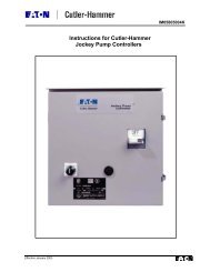
Effective January 2003<br />
<strong>Instructions</strong> <strong>for</strong> <strong>Cutler</strong>-<strong>Hammer</strong><br />
<strong>Diesel</strong> <strong>Engine</strong> <strong>Fire</strong> <strong>Pump</strong> <strong>Controllers</strong><br />
IM05805003K
IM05805003K Page i<br />
Effective January 2003<br />
Table of Contents<br />
1. INSTALLATION AND MOUNTING OF CONTROLLER............................................................. 1<br />
2. ELECTRICAL CONNECTIONS ....................................................................................................... 1<br />
2.1 WIRE SIZES....................................................................................................................................... 1<br />
3. SYSTEM PRESSURE CONNECTION.............................................................................................. 2<br />
4. MAIN DISPLAY PANEL .................................................................................................................... 2<br />
4.1 LCD DISPLAY.................................................................................................................................... 2<br />
4.2 ANNUNCIATORS ............................................................................................................................... 2<br />
4.3 MAIN SWITCH................................................................................................................................... 2<br />
4.4 FUNCTION (F1, F2, F3) AND MENU KEYS .......................................................................................... 2<br />
4.5 SILENCE AND RESET BUTTON ........................................................................................................... 2<br />
4.6 LAMP TEST BUTTON ......................................................................................................................... 2<br />
4.7 TIME/PRINT BUTTON ........................................................................................................................ 2<br />
5. OPERATION OF CONTROLLER .................................................................................................... 3<br />
5.1 OFF MODE ........................................................................................................................................ 3<br />
5.2 MANUAL MODE ................................................................................................................................3<br />
5.3 AUTO MODE ..................................................................................................................................... 3<br />
5.4 STOP MODES .................................................................................................................................... 3<br />
5.5 WEEKLY TEST TIMER........................................................................................................................ 3<br />
5.6 TEST MODE ...................................................................................................................................... 4<br />
5.7 RUN PERIOD TIMER (RPT) ................................................................................................................. 4<br />
5.8 SEQUENTIAL START TIMER............................................................................................................... 4<br />
6. PROGRAMMING THE MAIN CONTROLLER ............................................................................. 5<br />
6.1 TO PROGRAM THE CONTROLLER....................................................................................................... 5<br />
6.2 PROGRAM DECRIPTIONS................................................................................................................... 5<br />
6.2.1 Change Date ........................................................................................................................... 5<br />
6.2.2 Change time............................................................................................................................ 5<br />
6.2.3 Weekly Timer .......................................................................................................................... 5<br />
6.2.4 Run Period Timer ................................................................................................................... 5<br />
6.2.5 Language ................................................................................................................................ 5<br />
6.2.6 Pressure Transducer............................................................................................................... 6<br />
6.2.7 Pressure Start Pt..................................................................................................................... 6<br />
6.2.8 Pressure Stop Pt ..................................................................................................................... 6<br />
6.2.9 Low Suction Shutdown............................................................................................................ 6<br />
6.2.10 Printer Deviation .................................................................................................................... 6<br />
6.2.11 Current Pressure .................................................................................................................... 6<br />
6.2.12 Sequential Start....................................................................................................................... 6<br />
6.2.13 Stop Mode ............................................................................................................................... 6<br />
6.2.14 AC Failure Start ..................................................................................................................... 6<br />
6.2.15 Print Routine........................................................................................................................... 7<br />
6.2.16 Print Status ............................................................................................................................. 7<br />
6.2.17 Select Mode or Press Menu .................................................................................................... 7<br />
7. ALARM SIGNALS............................................................................................................................... 8<br />
7.1 BATTERY FAILURE ........................................................................................................................... 8<br />
7.2 CHARGER FAILURE........................................................................................................................... 8<br />
7.3 ENGINE RUN..................................................................................................................................... 8<br />
7.4 ENGINE OVERSPEED ......................................................................................................................... 8<br />
7.5 FAIL TO START ................................................................................................................................. 8<br />
7.6 RELIEF VALVE DISCHARGE............................................................................................................... 8<br />
7.7 HIGH ENGINE TEMPERATURE............................................................................................................ 8
Page ii IM05805003K<br />
7.8 LOW / HIGH FUEL ............................................................................................................................. 8<br />
7.9 LOW OIL PRESSURE .......................................................................................................................... 8<br />
7.10 LOW / HIGH RESERVOIR.................................................................................................................... 8<br />
7.11 LOW ROOM TEMPERATURE............................................................................................................... 8<br />
8. BATTERY CHARGERS ..................................................................................................................... 9<br />
9. OPERATING TEMPERATURE ........................................................................................................ 9<br />
10. INITIAL START UP.......................................................................................................................... 10<br />
10.1 AUTOMATIC START TEST................................................................................................................ 10<br />
10.2 MANUAL START TEST..................................................................................................................... 11<br />
10.3 TEST START TEST ........................................................................................................................... 11<br />
10.4 WEEKLY EXERCISER TEST .............................................................................................................. 11<br />
11. FIELD FAILURE ALARM SIMULATION .................................................................................... 12<br />
11.1 CHARGER FAILURE......................................................................................................................... 12<br />
11.2 BATTERY FAILURE ......................................................................................................................... 12<br />
11.3 LOW OIL PRESSURE ........................................................................................................................ 12<br />
11.4 HIGH ENGINE TEMPERATURE.......................................................................................................... 12<br />
11.5 ENGINE FAIL TO START................................................................................................................... 12<br />
11.6 ENGINE OVERSPEED ....................................................................................................................... 12<br />
11.7 OTHER ALARMS (PUMP ROOM ALARMS) ......................................................................................... 12<br />
12. PRINTER - RECORDER INSTRUCTIONS............................................................................... 13<br />
12.1 OPERATING PROCEDURE ................................................................................................................ 13<br />
12.2 SELF TEST FUNCTION ..................................................................................................................... 13<br />
12.3 PAPER LOADING............................................................................................................................. 13<br />
12.4 PRINT MODES ................................................................................................................................. 14<br />
12.4.1 Auto Print ............................................................................................................................. 14<br />
12.4.2 Manual Print......................................................................................................................... 14<br />
12.5 PRINT STATUS ................................................................................................................................14<br />
12.6 PRINTER DEVIATION....................................................................................................................... 14<br />
12.7 REPLACEMENT PAPER TYPE............................................................................................................ 15<br />
13. FACEPLATE DETAILS................................................................................................................. 16<br />
14. MENU FLOWCHART .................................................................................................................. 17<br />
15. APPENDIX A: ANNUNCIATOR ALARMS.............................................................................. 18<br />
16. APPENDIX B: PRINTER 'EVENT' MESSAGES ..................................................................... 19<br />
17. DIMENSIONS AND SHIPPING WEIGHT................................................................................. 20<br />
18. FIELD CONNECTIONS, TERMINAL BLOCK ........................................................................ 21<br />
19. TYPICAL SCHEMATIC............................................................................................................... 22<br />
Effective January 2003
IM05805003K Page 1<br />
Effective January 2003<br />
Installation & Maintenance<br />
Manual <strong>for</strong> <strong>Diesel</strong> <strong>Engine</strong><br />
<strong>Fire</strong> <strong>Pump</strong> Controller<br />
In order to familiarize yourself with the FD100 <strong>Diesel</strong> Controller, please read this instruction<br />
manual thoroughly and carefully. Retain the manual <strong>for</strong> future reference.<br />
1. Installation and Mounting<br />
Carefully unpack the diesel controller and<br />
inspect thoroughly.<br />
The controller should be located as close as is<br />
practical to the engine it controls and shall be<br />
within sight of the diesel engine and batteries,<br />
preferably ten feet or less.<br />
The FD100 controller is designed <strong>for</strong> either<br />
wall or floor mounting. Note that the controller<br />
is not free-standing and must be mounted with<br />
feet or bolted securely to a wall. Refer to the<br />
dimension drawing (Figure #3) in this manual<br />
<strong>for</strong> dimensional data.<br />
The enclosure should be mounted with<br />
fastening devices capable of supporting<br />
250lbs/114kg.<br />
2. Electrical Connections<br />
All electrical connections should meet national<br />
and local electrical codes and standards.<br />
The controller should be located or so protected<br />
that it will not be damaged by water escaping<br />
from pumps or pump connections. Current<br />
carrying parts of controllers shall be a<br />
minimum of 12 inches (305 mm) above the<br />
floor level.<br />
• Verify all data on the nameplate such as<br />
catalog number, polarity of grounding, AC<br />
line, battery voltage and system pressure.<br />
• Inspect all electrical connections,<br />
components and wiring <strong>for</strong> any visible<br />
damage and correct as necessary. Ensure<br />
that all electrical connections are tightened<br />
be<strong>for</strong>e being energized.<br />
• Refer to the appropriate field connection<br />
drawing affixed to the enclosure door, <strong>for</strong><br />
all wiring in<strong>for</strong>mation pertaining to the<br />
incoming AC power supply, batteries and<br />
engine wiring.<br />
• Install necessary conduit using proper<br />
methods and tools.<br />
• Terminals 1 through 12, located on the<br />
lower terminal block, are <strong>for</strong><br />
interconnection to the respective terminals<br />
on the diesel engine terminal block.<br />
• Incoming AC line voltage is clearly marked<br />
L,N and GD (ground) located on the lower<br />
terminal block.<br />
• Terminals 16 through 31, located on the<br />
lower terminal block, are <strong>for</strong><br />
interconnection of all remote alarm<br />
functions.<br />
*Do not apply an AC voltage to these<br />
terminals. Dry contact rating only.<br />
• Terminals 39 through 134, located on the<br />
Relay Board, are <strong>for</strong> connection of all<br />
output relay functions. These terminals are<br />
of the pull-apart variety <strong>for</strong> ease of wiring.<br />
• Input terminals on controller card are rated<br />
<strong>for</strong> 30 VDC.<br />
NOTE: All field connections and AC wiring must be<br />
brought into the enclosure through the lower<br />
right or bottom right side ONLY (refer to<br />
label affixed inside enclosure),<br />
*OTHERWISE WARRANTY IS VOID.*<br />
2.1 Wire Sizes<br />
• For control wiring, use #14 AWG wire<br />
<strong>for</strong> all electrical connections except<br />
battery connections.<br />
• For battery connection, terminals 6, 7, 8<br />
and 11, use the following:<br />
#10 AWG: 0' to 25' (7.62 m)<br />
# 8 AWG: 25' to 50' (15.2 m)
Page 2 IM05805003K<br />
3. System Pressure Connection 4.2 Annunciators<br />
The alarm and status indicators are located in<br />
the top portion of the main display panel and<br />
will illuminate only if the situation occurs.<br />
The FD100 is supplied with a Pressure<br />
Transducer or, as an option, a Mercoid<br />
Pressure Switch. The controller is provided<br />
with a 1/4" NPT female system pressure<br />
connection located on the bottom, external<br />
side of the enclosure. The connection should<br />
be installed as per NFPA, pamphlet No. 20.<br />
The "TEST" drain connection, located to the<br />
left of the system pressure connection, should<br />
be piped to a drain or to waste.<br />
NOTE: Water lines to the drain valve and pressure<br />
switch must be free from dirt and<br />
contamination.<br />
The main controller panel interfaces with<br />
either the pressure transducer or the optional<br />
Mercoid pressure switch. The controller must<br />
be programmed <strong>for</strong> the appropriate device.<br />
Using the standard pressure transducer, the<br />
actual pressure is displayed on the top right<br />
hand corner of the LCD display. Precise start<br />
and stop pressure set points can be<br />
programmed into the controller via the<br />
membrane switches. Pressure readings are<br />
also displayed on the printer during alarm<br />
situations or pressure deviations.<br />
With the Mercoid pressure switch option, the<br />
LCD will display "OK" if the pressure is<br />
satisfied, and "LOW", if the contacts on the<br />
pressure switch change state. The printer will<br />
indicate "Low Pressure" on the paper display<br />
when the pressure is not satisfied.<br />
4. Main Display Panel<br />
The main display panel located inside the<br />
enclosure, behind the breakable glass panel,<br />
serves many operator interface functions<br />
(refer to Figure #1 <strong>for</strong> the main display panel<br />
layout):<br />
• LCD Display<br />
• Annunciators<br />
• Main Switches<br />
• Ammeter and Voltmeter <strong>for</strong> Each Battery<br />
• Pressure Indicator<br />
• Programming Functions<br />
4.1 LCD Display<br />
The LCD display located on the bottom of<br />
the main display panel indicates both the<br />
voltage and current reading of each battery as<br />
well as the system pressure, in PSI.<br />
The LCD display is also used while<br />
programming the diesel controller.<br />
Effective January 2003<br />
The indicators are color coded to signify the<br />
urgency of the alarm:<br />
GREEN: Normal Running Condition<br />
RED: Critical Alarm<br />
YELLOW: Supervisory Alarm<br />
4.3 Main Switch<br />
Four membrane switches labeled AUTO,<br />
MANUAL, TEST and OFF, each equipped<br />
with an LED indicator, are clearly marked <strong>for</strong><br />
easy operation of the controller.<br />
4.4 Function (F1,F2,F3) and MENU Keys<br />
There are four membrane switches, F1, F2,<br />
F3 and MENU which are dedicated to<br />
programming the controller. Refer to section<br />
6 <strong>for</strong> programming of the controller.<br />
4.5 Silence and Reset Button<br />
Used to silence and/or reset prescribed alarms<br />
as per NFPA Pamphlet No. 20.<br />
4.6 Lamp Test Button<br />
When depressed, the LED's will illuminate<br />
sequentially, row by row. This function can<br />
be utilized at any time during the operation of<br />
the diesel controller.<br />
4.7 Time/Print Button<br />
This button toggles between two functions.<br />
When initially depressed the LCD display<br />
will indicate:<br />
TOP: Actual date and time<br />
BOTTOM: Weekly Test Timer, date and<br />
time.<br />
BOTTOM: Quantity of messages stored<br />
RIGHT in memory.<br />
When depressed again the controller will<br />
prompt the user to hold the button <strong>for</strong> 3<br />
seconds (at which time an audible tone is<br />
heard) after which the stored event and alarm<br />
messages will be transmitted to the printer.<br />
This is only applicable when the 'Print<br />
Routine' is set <strong>for</strong> Manual Print, otherwise<br />
the data is sent directly to the printer without<br />
user intervention. Refer to Section 12.<br />
The "Time/Print" key is not functional when<br />
the controller is in the OFF mode.
IM05805003K Page 3<br />
5. Operation of Controller<br />
Be<strong>for</strong>e accessing any mode, you must return<br />
to the OFF mode.<br />
5.1 OFF Mode<br />
In the OFF position the controller prevents<br />
the engine from starting and resets the<br />
following alarms:<br />
A drop in pressure, 'Remote Start' signal, a<br />
signal from the 'Deluge Valve' or Weekly<br />
Test Timer will initiate the "attempt to start"<br />
cycle. This cycle consists of 6 crank periods<br />
of 15 seconds duration separated by 5 rest<br />
periods of 15 seconds duration. Battery 1<br />
and Battery 2 are alternated <strong>for</strong> each crank<br />
cycle. In the event that one battery is<br />
inoperative or missing, the controller will<br />
lock-in on the remaining battery during the<br />
cranking sequence. Once the engine is<br />
running, the controller will stop all further<br />
cranking.<br />
• Overspeed<br />
• Charger Failure<br />
• Battery Failure<br />
• Fail to Start<br />
• Low Oil Pressure<br />
• High <strong>Engine</strong> Temperature<br />
The OFF position will silence all alarms.<br />
Three (3) sets of alarm contacts are provided<br />
to indicate that the controller is in the "OFF"<br />
mode. The contacts are rated <strong>for</strong> 10 A @ 220<br />
VAC / 32 VDC. Terminals 120 to 128.<br />
5.2 Manual Mode<br />
This position allows the starting of the<br />
engines using the manual crank buttons,<br />
Crank #1 and Crank #2, located below the<br />
main display panel. For added cranking<br />
capacity, both Crank buttons can be<br />
depressed simultaneously.<br />
The engine can be stopped by the 'Local Stop'<br />
pushbutton or by placing the controller in the<br />
OFF mode. The engine will automatically<br />
stop in the case of an OVERSPEED<br />
condition.<br />
All alarms, except <strong>for</strong> "FAIL TO START",<br />
are active in the MANUAL mode.<br />
CAUTION: Only depress Crank #1 or<br />
Crank #2 pushbuttons with controller in the<br />
'MANUAL' mode.<br />
Do not depress the crank pushbuttons in any<br />
other mode or while engine is running.<br />
Doing so can result in serious damage to the<br />
engine.<br />
Three (3) sets of alarm contacts are provided<br />
to indicate that the controller is in the<br />
"MANUAL" mode. The contacts are rated<br />
<strong>for</strong> 10 A @ 220 VAC / 32 VDC. Terminals<br />
63 to 71.<br />
5.3 AUTO Mode<br />
Placing the controller in the AUTO mode<br />
illuminates the "SWITCH IN AUTO"<br />
annunciator. The controller is now ready to<br />
start the engine in an emergency situation.<br />
Effective January 2003<br />
5.4 Stop Modes<br />
The Stop Mode is programmable <strong>for</strong> either<br />
'Manual Stop' or 'Auto Stop' (see Figure #2).<br />
Note that the engine can be stopped at any<br />
time by placing the controller in the OFF<br />
position or automatically in case of an<br />
OVERSPEED condition.<br />
Manual Stop Mode: the engine will continue<br />
to run until the 'Local Stop' or 'Remote Stop'<br />
pushbutton is depressed, providing all<br />
starting causes have been eliminated.<br />
NOTE: When the controller starts in this mode<br />
there is a 15 second time delay in which<br />
the ‘Local Stop’ pushbutton will have no<br />
effect.<br />
Auto Stop Mode: the engine will continue to<br />
run until the running period timer (RPT) has<br />
timed out (factory set at 30 minutes) and all<br />
starting causes have been eliminated.<br />
5.5 Weekly Test Timer<br />
Each diesel controller is equipped with a<br />
Weekly Test Timer, 24 hour clock, to<br />
automatically exercise the engine once a<br />
week. The controller initiates the starting<br />
sequence by opening the drain valve resulting<br />
in a simulated system pressure loss. The<br />
drain valve is automatically closed once the<br />
controller receives an "ENGINE RUN"<br />
signal. The engine will continue to run <strong>for</strong> a<br />
minimum of 30 minutes or <strong>for</strong> the duration of<br />
the RPT setting, whichever is greater.<br />
"Weekly Test Started" will be indicated on<br />
the hard copy printout.<br />
In the event that the engine is inoperative at<br />
the time the Weekly Test is to be initiated, the<br />
Weekly Test will commence immediately after<br />
the engine is put in service. This ensures that<br />
the engine is exercised at least once a week<br />
<strong>for</strong> the time specified as per NFPA Pamphlet<br />
No. 20.<br />
In order to protect the engine, during the<br />
Weekly Test sequence, an OVERSPEED<br />
condition, LOW OIL PRESSURE or HIGH<br />
ENGINE TEMP alarm will automatically<br />
shutdown the engine.
Page 4 IM05805003K<br />
5.6 TEST Mode<br />
Placing the controller in the TEST position<br />
initiates a starting sequence by opening the<br />
drain valve resulting in a pressure loss. The<br />
controller will start the engine in the<br />
automatic mode.<br />
The TEST sequence can be terminated by<br />
putting the controller in the OFF mode,<br />
otherwise the STOP mode prevails as<br />
programmed.<br />
All alarms are active in the test mode. In<br />
order to protect the engine, in the test mode,<br />
an OVERSPEED condition, LOW OIL<br />
PRESSURE or HIGH ENGINE TEMP alarm<br />
will automatically shutdown the engine.<br />
5.7 Run Period Timer<br />
The Run Period Timer (RPT) per<strong>for</strong>ms the<br />
automatic stopping function in a <strong>Fire</strong> <strong>Pump</strong><br />
Controller after a start initiated by the<br />
pressure switch during automatic operation.<br />
The purpose of the RPT is to ensure that the<br />
engine is not subjected to frequent starts in<br />
response to the pressure. Refer to Section 6<br />
<strong>for</strong> programming of the RPT.<br />
5.8 Sequential Start Timer<br />
The Sequential Start Timer is standard in all<br />
diesel fire pump controllers.<br />
“The controller <strong>for</strong> each unit of multiple<br />
pump units operating in parallel shall<br />
incorporate a sequential timing device to<br />
prevent any one motor from starting<br />
simultaneously with any other motor. If<br />
water requirements call <strong>for</strong> more than one<br />
pumping unit to operate, the units shall start<br />
at intervals of 5 to 10 seconds. Failure of a<br />
leading motor to start shall not prevent<br />
subsequent pumping units from starting” –<br />
NFPA, Pamphlet 20, Chapter 7.<br />
The sequential start timer (SST) delays the<br />
starting of a fire pump in response to the<br />
pressure switch. It does not delay a<br />
pushbutton or emergency handle start..<br />
With a SST in each controller, any pump may<br />
be selected as the lead pump by appropriate<br />
setting of the timers. If the lead pump<br />
restores the pressure in less than the time<br />
Effective January 2003<br />
delays applied to the lag pumps, then the lag<br />
pumps will not start.<br />
In addition, the provision of a sequential start<br />
timer, set to a few seconds delay, will prevent<br />
the lead pump controller from responding to<br />
momentary hydraulic transient pressure loss<br />
which would otherwise start the fire pump<br />
unnecessarily.<br />
The SST can be programmed from 0 – 300<br />
seconds. Typically, each pump should be<br />
delayed by 10 seconds from the pump ahead<br />
of it. If hydraulic transients are a problem,<br />
all timers can be adjusted <strong>for</strong> a few seconds<br />
extra time delay.
IM05805003K Page 5<br />
6. Programming of the Main<br />
Controller<br />
>> The controller is programmable
Page 6 IM05805003K<br />
6.2.6 Pressure Transducer<br />
When selected as YES, the controller will<br />
start based on the signal from the pressure<br />
transducer.<br />
When selected as NO, the engine will start<br />
when the controller detects a contact closure<br />
between terminals 31+11, i.e. Mercoid<br />
pressure switch start.<br />
For both starting conditions above, the<br />
Sequential Start Timer is activated when<br />
selected.<br />
6.2.7 Pressure Start Pt<br />
The value programmed determines at what<br />
pressure the controller will initiate a start<br />
command to the engine.<br />
The pressure range is: 1-500 PSI<br />
6.2.8 Pressure Stop Pt<br />
The value programmed determines at what<br />
pressure the system must reach be<strong>for</strong>e the<br />
controller will STOP the engine, either<br />
manually via the STOP pushbutton or<br />
automatically via the RPT timer. If the actual<br />
pressure does not exceed the STOP pressure<br />
value, the engine will continue to run.<br />
The pressure range is: 1-500 PSI<br />
6.2.9 Low Suction Shutdown<br />
This function monitors a contact closure<br />
between terminals 29+11. If shutdown is<br />
disabled, the LCD display will show low<br />
suction and the engine will continue to run.<br />
If shutdown is enabled, to prevent the<br />
controller from responding to momentary<br />
hydraulic transient pressure loss (which<br />
would otherwise shut down the engine<br />
unnecessarily), a time delay must be<br />
programmed to ensure a steady state.<br />
The shutdown time delay is selectable<br />
between 0-30 seconds. Upon detecting a<br />
steady state contact closure, the engine will<br />
turn off.<br />
The reset mode of the engine is user<br />
selectable. For AUTOMATIC reset, a time<br />
delay between 0- 30 seconds is selected, after<br />
which the controller observes the input <strong>for</strong> a<br />
true signal, and if true, will not allow the<br />
engine to restart. If false, the controller will<br />
function as normal and respond to a start<br />
signal.<br />
If MANUAL reset is selected, the RESET<br />
pushbutton must be depressed to reset the<br />
controller. If the situation continues to exist,<br />
the controller will not restart the engine and<br />
the alarm will reappear.<br />
Effective January 2003<br />
The LCD display will indicate ‘Low Suction<br />
Shutdown’ in both situations.<br />
NFPA 20, Section 2-9.9, specifically prohibits the<br />
installation of any device in the suction piping<br />
that will restrict starting or stopping of the fire<br />
pump. <strong>Cutler</strong>-<strong>Hammer</strong> assumes no liability when<br />
this function is used.<br />
6.2.10 Printer Deviation<br />
This value determines how often to print<br />
system pressure fluctuations as programmed<br />
by the user. In effect, it per<strong>for</strong>ms as a chart<br />
recorder.<br />
For example, if 10 PSI is programmed, each<br />
time the system pressure fluctuates by 10<br />
PSI, up or down, the actual pressure is<br />
recorded in memory and printed, tagged with<br />
a date and time. This method avoids<br />
continual, time-based printing of unnecessary<br />
pressure values.<br />
6.2.11 Current Pressure<br />
Allows the user to view the actual pressure<br />
during programming of the <strong>Diesel</strong> Controller.<br />
6.2.12 Sequential Start<br />
This parameter allows you to program a start<br />
delay after a start request. To bypass the start<br />
delay, set the parameter to zero.<br />
The programmable range is: 0-300 sec<br />
6.2.13 Stop Mode<br />
If ‘Set <strong>for</strong> Manual’, once started, the engine<br />
MUST be stopped manually by depressing<br />
the STOP pushbutton located on the flange,<br />
regardless of the starting cause. If ‘Set <strong>for</strong><br />
Auto’, the RPT becomes operative.<br />
6.2.14 AC Failure Start<br />
If ‘Enabled’, the controller will automatically<br />
start upon the loss of AC power. There will<br />
be a non-adjustable delay of 180 seconds<br />
be<strong>for</strong>e the AC failure is detected. An<br />
additional delay can be set if desired. Time<br />
range is between 0 & 300 seconds. If<br />
‘disabled’ AC power failure will have no<br />
affect on the starting of the engine.
IM05805003K Page 7<br />
6.2.15 Print Routine<br />
If selected <strong>for</strong> Auto, the messages will print<br />
immediately without any user intervention.<br />
If selected <strong>for</strong> Manual, the messages will be<br />
stored in the controller’s memory and will<br />
print once the TIME/PRINT key is pushed<br />
and held <strong>for</strong> 3 seconds.<br />
To avoid paper build up inside the enclosure,<br />
it is recommended that the print mode be<br />
selected as ‘MANUAL’ during normal<br />
operation of the controller.<br />
6.2.16 Print Status<br />
If selected as ‘NO’, a Status report will not<br />
print when exiting the programming menu. If<br />
selected as ‘YES’, after exiting the program<br />
mode, and pressing the Time/Print button <strong>for</strong><br />
3 seconds, the programmed parameters and<br />
selected controller readings will be printed.<br />
This is most helpful during and after<br />
commissioning of the <strong>Fire</strong> <strong>Pump</strong> Controller.<br />
A sample status printout is shown in section<br />
12:<br />
6.2.17 Select Mode or Press Menu<br />
If programming of the unit is complete<br />
pressing the mode keys will put the controller<br />
back into operation.<br />
Effective January 2003
Page 8 IM05805003K<br />
7. Alarm Signals (Annunciator<br />
Panel)<br />
Each FD100 <strong>Diesel</strong> Controller is equipped<br />
with all the alarms as shown on page 18.<br />
Unused alarms can be activated at any time.<br />
Refer to the schematic supplied with the<br />
FD100 <strong>for</strong> alarm connections.<br />
Refer to Appendix A: "Annunciator Alarms"<br />
affixed inside the enclosure, which describes<br />
each alarm, method of resetting, associated<br />
terminal reference number, common trouble<br />
alarm and print out. Section 12 describes the<br />
"Print Mode".<br />
7.1 Battery Failure<br />
There are two annunciators on the alarm<br />
panel <strong>for</strong>, "Battery #1 Failure" and "Battery<br />
#2 Failure". The alarm is activated during<br />
the cranking cycle when the controller detects<br />
a weak or discharged battery, i.e. 67% of<br />
rated voltage, or less, or whenever a battery<br />
cable is disconnected.<br />
7.2 Charger Failure<br />
There are two annunciators on the alarm<br />
panel <strong>for</strong>, "Charger #1 Failure" and "Charger<br />
#2 Failure". The alarm is activated when the<br />
supply power to the charger is lost or when<br />
the charger malfunctions (alarm contacts are<br />
fed into the controller from the charging<br />
unit). The engine continues to run. To avoid<br />
nuisance power failures, a 20 second delay is<br />
built in to the Charger Failure alarm<br />
actuation circuit.<br />
7.3 <strong>Engine</strong> Run<br />
This annunciator illuminates when the<br />
controller receives a running signal from the<br />
diesel engine.<br />
7.4 <strong>Engine</strong> Overspeed<br />
An "<strong>Engine</strong> Overspeed" alarm will shutdown<br />
the engine regardless of the start condition -<br />
in all modes. The signal is sent from the<br />
engine to the controller.<br />
7.5 Fail To Start<br />
After 6 cranking attempts, three attempts per<br />
battery, the "Fail To Start" annunciator will<br />
illuminate. Attention to the diesel and its<br />
associated equipment is required<br />
immediately.<br />
7.6 Fuel Spill*<br />
Indicates that the relief valve has been<br />
manually opened. This will cause a start of<br />
the engine once the pressure drops below the<br />
set value.<br />
Effective January 2003<br />
7.7 High <strong>Engine</strong> Temperature<br />
Indicates that the coolant temperature in the<br />
water jackets is extremely hot. The over<br />
temperature switch on the engine signals the<br />
controller. The engine continues to run in the<br />
AUTO and MANUAL modes. In the<br />
"TEST" mode and during the weekly test<br />
cycle the engine will shutdown.<br />
7.8 Low / High Fuel **<br />
(When Fuel Level Switch Wired)<br />
Indicates that the engine fuel supply is<br />
low / high. The engine continues to run.<br />
7.9 Low Oil Pressure<br />
The controller has an inherent delay to<br />
bypass the low oil pressure alarm during<br />
engine start up. After the delay, should the<br />
engine receive a 'Low Oil Pressure' signal,<br />
the controller will initiate an alarm. The<br />
engine will continue to run in the 'AUTO' and<br />
'MANUAL' mode. In the 'TEST' mode and<br />
during the weekly test cycle this alarm will<br />
automatically shutdown the engine. This<br />
situation will result in serious engine damage<br />
if kept running.<br />
7.10 Low / High Reservoir<br />
Indicates that the water reservoir level is low<br />
/ high. (Signal supplied by others)<br />
7.11 Low Room Temperature<br />
(When Thermostat Installed)<br />
Should a "Low Room Temperature" alarm<br />
occur the engine will continue to run.<br />
* Software versions be<strong>for</strong>e V2.91 have a<br />
Relief Valve Discharge alarm in lieu of the<br />
Fuel spill alarm.<br />
** Software versions prior to V2.91 have an<br />
audible alarm <strong>for</strong> Low / High Fuel which<br />
followed the input signal from the fuel tank.
IM05805003K Page 9<br />
8. Battery Chargers<br />
Extra care must be taken while working near<br />
the chargers. The chargers contain live parts<br />
and caution must be exercised with AC<br />
power applied to the units.<br />
Battery chargers are independent chargers<br />
producing a maximum of 10 amps each at<br />
full rate. The battery chargers are fully<br />
electronic and will limit the output current to<br />
10 amps even during a continued short<br />
circuit.<br />
The green LED on the charger indicates the<br />
presence of AC power.<br />
Once the battery comes up to full charge the<br />
charger will automatically go into a float rate<br />
mode and will provide the exact trickle<br />
current required to maintain the batteries<br />
fully charged.<br />
The chargers are equipped with two sets of<br />
dry, Form C contacts. One to detect low<br />
battery voltage, J2, (not wired) indicated with<br />
a red LED marked as LOW VOLTS, and the<br />
other to detect the loss of AC power, J3,<br />
wired to the controller.<br />
The required charge mode can be selected<br />
using the 3-position toggle switch located<br />
near the center of the instrument panel of the<br />
charger.<br />
The three available modes are:<br />
• Continuous "FLOAT"<br />
• Continuous "EQUALIZE"<br />
(not recommended <strong>for</strong> more than 12 hours)<br />
• "AUTOMATIC" (factory setting)<br />
NOTE: It is essential that the toggle switch be<br />
left in the automatic mode when the<br />
controller is not supervised.<br />
In this mode "EQUALIZE" is automatically<br />
initiated by a low battery voltage and<br />
automatically terminated by a high battery<br />
voltage. This assures that the battery will<br />
receive an "EQUALIZE" charge only when<br />
needed and only <strong>for</strong> the required period of<br />
time.<br />
The chargers have reverse polarity protection<br />
which prevents the charger from starting on a<br />
battery which has been connected in reverse<br />
polarity or having a voltage below a certain<br />
minimum, as indicated by the red LED.<br />
Two other LED's are provided to indicate<br />
which mode the charger is operating in,<br />
FLOAT or EQUALIZE.<br />
Note that the two chargers are rotated 180 0<br />
from each other. A label affixed to each<br />
charger clearly indicates the position of the 3position<br />
switch and the indication of the five<br />
LED's.<br />
Effective January 2003<br />
NOTE: All of the charger potentiometers are<br />
factory set and are based on the<br />
required current charging rates, and<br />
battery voltages. DO NOT adjust these<br />
potentiometers. Doing so will void<br />
warranty.<br />
9. Operating Temperature<br />
The operating temperature range of the<br />
FD100 is: -20 0 C to 70 0 C.<br />
Temperatures lower or higher than those<br />
specified may cause damage to the diesel<br />
engine controller.
Page 10 IM05805003K<br />
10. Initial Start Up<br />
1. Ensure that circuit breakers CB1 and CB2 are in the OFF (0) position.<br />
2. Ensure that AC power is supplied to terminals L and N, and GD is grounded.<br />
3. Connect engine batteries to the controller, terminals 6,8 and 11. If batteries are connected in wrong<br />
polarity the battery voltage will read zero.<br />
Note that terminals 6A and 8A are <strong>for</strong> factory use only and NOT <strong>for</strong> external connections.<br />
4. The Chargers MUST be in placed in the AUTO mode (refer to toggle switch on chargers - factory set in<br />
the AUTO mode).<br />
5. Turn circuit breakers CB1 and CB2 ON ("1" position).<br />
6. Turn printer ON after CB1 and/or CB2 have been turned ON.<br />
7. Pressure (start) is factory preset at 1 PSI.<br />
8. Place the controller in the 'OFF' mode by depressing the "OFF" button.<br />
9. Ensure that the <strong>Diesel</strong> is programmed to user's specifications. Refer to section 6 in this manual.<br />
Refer to STATUS printout <strong>for</strong> factory set parameters.<br />
10.1 Automatic Start Test<br />
Test printer while in Auto mode as per Section 12 of manual.<br />
Depress the "AUTO" button.<br />
LED on "AUTO" button will light and Annunciator "Switch in Auto" will illuminate.<br />
Ensure that water pressure is available and the LCD display on the Display Panel<br />
is reading the system pressure, in PSI.<br />
Decrease water pressure. Controller will begin its cranking cycle.<br />
Should the engine fail to start after 6 crank and rest cycles, the audible alarm will sound<br />
and the "Fail To Start" annunciator will illuminate. Depress "OFF" button to silence alarm.<br />
When engine starts, "<strong>Engine</strong> Run" annunciator illuminates.<br />
Increase water pressure above programmed STOP point. Press the stop pushbutton on the<br />
enclosure. If the pressure is satisfied, the engine will stop.<br />
Effective January 2003<br />
OR<br />
If STOP mode is programmed <strong>for</strong> "Auto-Stop", engine will stop after Run Period Timer times<br />
out and pressure is satisfied. RPT is programmed by the user, factory set at 30 minutes.<br />
If Sequential Timer is > 0 seconds, automatic start will be delayed by the number of seconds<br />
programmed.<br />
If AC Power Failure is ENABLED, automatic start will be delayed by the number of seconds<br />
programmed upon a power failure.
IM05805003K Page 11<br />
10.2 Manual Start Test<br />
Depress the "Manual" button. The LED on the button will illuminate.<br />
Fuel Solenoid relay will change state.<br />
Press Crank No.1 pushbutton. <strong>Engine</strong> cranks and starts, "<strong>Engine</strong> Run" annunciator illuminates.<br />
Press "OFF" button. Wait <strong>for</strong> engine to stop. Push "Manual" button then press Crank No.2<br />
pushbutton. <strong>Engine</strong> cranks and starts, "<strong>Engine</strong> Run" annunciator illuminates.<br />
Press "OFF" button. <strong>Engine</strong> will stop.<br />
10.3 Test Start Test<br />
Depress the "Test" button. LED on button will illuminate.<br />
Drain Valve Solenoid will energize and reduce pressure. Controller will start engine<br />
automatically. "<strong>Engine</strong> Run" annunciator illuminates.<br />
Press "OFF" button. <strong>Engine</strong> will stop.<br />
10.4 Weekly Exerciser Test<br />
Depress "OFF" button.<br />
Effective January 2003<br />
NOTE: <strong>Engine</strong> will stop if Low Oil Pressure, High Water Temp or<br />
Overspeed alarms are detected.<br />
To test the Weekly Exerciser, preprogram the controller to initiate the test at a time suitable to<br />
the user.<br />
Depress "AUTO" button.<br />
At programmed time and date the drain valve solenoid will open. When the pressure drops below<br />
the start PSI value, engine will start, "<strong>Engine</strong> Run" annunciator will illuminate, and drain valve<br />
solenoid will close.<br />
Press "OFF" button. <strong>Engine</strong> will stop.<br />
Reprogram Weekly Exerciser <strong>for</strong> normal operation.<br />
NOTE: <strong>Engine</strong> will stop if Low Oil Pressure, High Water Temp or<br />
Overspeed alarms are detected.
Page 12 IM05805003K<br />
11. Field Failure Alarm<br />
Simulation<br />
Ensure that CB1 and/or CB2 are in the ON<br />
position prior to applying power to the printer<br />
(refer to nameplate above printer).<br />
Ensure that both CB1 and CB2 are in the ON<br />
position and that there is AC power to the<br />
chargers. Place the controller in either the<br />
AUTO or MANUAL mode.<br />
NOTE: - For all engine alarms, the <strong>Engine</strong><br />
Trouble Alarm relay will energize.<br />
- Do not put an AC voltage on these<br />
contacts.<br />
11.1 Charger Failure<br />
Remove AC power to the diesel controller panel.<br />
After a delay of 180 seconds, the alarm will<br />
sound and both Charger #1 Failure and Charger<br />
#2 Failure indicating LED’s will display. Or,<br />
jumper 11 & 22, 11 & 23; [ 11 is Battery<br />
(negative)].<br />
After test, reapply AC power to continue testing<br />
of other alarms. To reset alarm go to OFF mode<br />
and then back into AUTO or MANUAL mode.<br />
11.2 Battery Failure<br />
Turn OFF CB1. Alarm will sound and Battery<br />
Failure #1 will indicate in the display.<br />
To reset alarm go to OFF mode and then back<br />
into AUTO or MANUAL mode.<br />
Turn ON CB1 and turn CB2 OFF. Alarm will<br />
sound and Battery Failure #2 will indicate in the<br />
display. Reset alarms as per above.<br />
NOTE:Do not turn off both CB1 and CB2<br />
simultaneously. Otherwise power will<br />
be lost to the controller card.<br />
NOTE:For the following tests, while controller<br />
is in the AUTO or MANUAL mode,<br />
place a JUMPER between terminal 2 &<br />
11. This will give an ENGINE RUN<br />
signal to the controller. Or, you can run<br />
the engine.<br />
There is an inherent 15 second delay <strong>for</strong><br />
detecting alarms after an ENGINE RUN<br />
signal.<br />
11.3 Low Oil Pressure<br />
Jumper 4 & 11. Alarm will sound and indicate<br />
on the display. To silence alarm, controller must<br />
be in the OFF mode. If the engine is wired to<br />
the panel and the engine itself is NOT running,<br />
the LOW OIL PRESSURE alarm will<br />
automatically alarm after the 15 second delay,<br />
with terminals 2 and 11 jumpered.<br />
Effective January 2003<br />
11.4 High <strong>Engine</strong> Temperature<br />
Jumper 5 & 11. Alarm will sound and indicate<br />
on display. To silence alarm, controller must be<br />
in the OFF mode. Note that the LOW OIL<br />
PRESSURE alarm will also indicate if terminal<br />
4 is wired from the engine to the panel and the<br />
engine is not physically running.<br />
11.5 <strong>Engine</strong> Fail to Start<br />
(ALL ENGINES EXCEPT CATERPILLAR)<br />
1. Disconnect field wires #9 & #10 on <strong>Fire</strong><br />
<strong>Pump</strong> Controller & initiate automatic<br />
start (Place controller in TEST mode).<br />
Note that actual engine will not crank<br />
thus reducing wear and tear on its<br />
starters and batteries.<br />
Caterpillar <strong>Engine</strong>s: Install a wire<br />
jumper between terminals 1 & 12 and<br />
initiate automatic start.<br />
2. Allow pressure to drop and begin<br />
cranking sequence.<br />
3. Wait 180 seconds to allow <strong>for</strong> 3 cranks<br />
per battery (15 seconds cranking, 15<br />
seconds rest, 6 times).<br />
4. Alarm will sound and Fail To Start<br />
indicator will display. To silence alarm,<br />
place controller in the OFF mode.<br />
11.6 <strong>Engine</strong> Overspeed<br />
Mechanically close speed switch relay on the<br />
diesel engine or jumper 3 & 11. Alarm will<br />
sound, <strong>Engine</strong> Overspeed indicator will display,<br />
and the fuel stop relay will energize.<br />
To silence alarm, place controller in the OFF<br />
mode.<br />
11.7 Other Alarms (<strong>Pump</strong> Room Alarms)<br />
To test pump room alarms, such as Low Fuel,<br />
Low Room Temp etc., place a jumper between<br />
terminal 11 and the corresponding alarm<br />
terminal input (refer to Appendix A affixed to<br />
controller door).<br />
NOTE: The <strong>Pump</strong> Room Trouble relay will also<br />
activate.
IM05805003K Page 13<br />
12. Printer - Recorder <strong>Instructions</strong><br />
The microprocessor-controlled printer is<br />
supplied as standard with all <strong>Diesel</strong> <strong>Fire</strong> <strong>Pump</strong><br />
<strong>Controllers</strong>. Mounted inside the enclosure the<br />
printer-recorder provides a hard copy status<br />
report of all alarms, events, voltage, system<br />
pressure, weekly test timer and programmed<br />
parameters of the controller. Each alarm printout<br />
is stamped with the time and date that can be<br />
used as a trouble-shooting tool to determine<br />
start-up causes and exact times of all events.<br />
Note: Printer shipped with controller may differ than<br />
shown above.<br />
12.1 Operating Procedure<br />
The printer-recorder is shipped from the factory<br />
with two rolls of paper.<br />
Caution must be taken while inside the<br />
controller to avoid electrical shocks.<br />
The functions of operating controls are as<br />
follows:<br />
Control Function<br />
L.E.D. Indicates ‘power on’ when<br />
green and ‘paper out’ when<br />
orange<br />
Switch Power off in down position<br />
Power on in up position<br />
Latch To secure main body of the<br />
printer to mounting enclosure.<br />
Effective January 2003<br />
12.2 Self Test Function<br />
To activate self-test feature, press and hold the<br />
feed button then turn the power on. To stop the<br />
self-test be<strong>for</strong>e the end of the message, power<br />
down the printer.<br />
12.3 Paper Loading<br />
Remove printer chassis from enclosure by<br />
turning the latch counter clockwise.<br />
Pull out chassis until it stops.<br />
Install the paper spindle into a new roll of<br />
thermal paper. Position the roll of paper so that<br />
it will feed from the top, then place the roll and<br />
spindle into the paper support brackets, making<br />
certain that the paper is level. It is recommended<br />
that square and clean cut edge is used <strong>for</strong> entry<br />
of paper into the printer mechanism – scissor cut<br />
preferred.<br />
To load paper, turn on the power. Now feed the<br />
cut edge of the paper into the guide until the<br />
paper stops. Press feed button, paper will<br />
advance as long as button is held. Feed paper<br />
until lead edge lines up with paper cutter.<br />
At this time it is recommended that a self-test be<br />
per<strong>for</strong>med to ensure that the paper is installed<br />
correctly, (thermal side up) and that it is feeding<br />
properly.<br />
In the event of a paper jam condition do not<br />
<strong>for</strong>ce the paper into the unit, or try to pry the<br />
paper out of the unit, this may damage the<br />
thermal print mechanism. Disconnect primary<br />
power and interface cable be<strong>for</strong>e servicing the<br />
unit. Carefully remove paper with a set of<br />
tweezers, or a small pair of needle nose<br />
pliers. If the paper cannot be cleared, remove the<br />
face plate by removing the five Philips head<br />
screws and nuts holding the face plate. This will<br />
allow access to the printer mechanism.<br />
Once paper is cleared from the mechanism,<br />
re-assemble the unit. At this time, re-load paper.<br />
NOTE: Do not remove jumpers inside of printer
Page 14 IM05805003K<br />
12.4 Print Modes<br />
While in the MENU mode, the 'PRINT<br />
ROUTINE' can be set up <strong>for</strong> either 'Auto' or<br />
'Manual'.<br />
12.4.1 Auto Print<br />
Messages will print directly to the printer as the<br />
event or alarm occurs.<br />
*DO NOT LEAVE IN THIS MODE*<br />
12.4.2 Manual Print<br />
The event and alarm messages are stored in<br />
memory until the 'Time/Print' key is depressed,<br />
at which time all stored data is printed. The<br />
controller will store up to 1024 messages on a<br />
First In-First Out basis. To print the stored data<br />
hold the 'Time/ Print' key <strong>for</strong> 3 seconds or more.<br />
DO NOT REMOVE POWER FROM PRINTER<br />
UNTIL ALL MESSAGES ARE PRINTED,<br />
OTHERWISE INFORMATION WILL BE LOST.<br />
12.5 Print Status<br />
When programmed as YES, the printer will print<br />
the "STATUS" of the controller upon exiting the<br />
program mode and only after selecting AUTO,<br />
MANUAL or TEST mode on the main switch.<br />
12.6 Printer Deviation<br />
Is used to determine how often to print system<br />
pressure fluctuations, in PSI, as programmed by<br />
the user.<br />
For example, if 10 PSI is programmed, each<br />
time the system pressure varies by 10 PSI or<br />
greater, the actual pressure, date and time will be<br />
printed on the printout display (if a Mercoid<br />
Pressure Switch is supplied this parameter has<br />
no effect).<br />
The programming of the print mode is detailed<br />
in Section 6.<br />
Effective January 2003<br />
"STATUS" Printout<br />
Alarm & Message Printout
IM05805003K Page 15<br />
12.7 Replacement Paper Type<br />
The printer-recorder uses a thermographic<br />
printing paper on a 2-3/4” diameter roll which<br />
is 2-1/4” wide and having a plastic core with<br />
a 7/16” hole. Suitable paper is available at<br />
most office-supply stores. See list below<br />
depicting the office supply stores and their<br />
respective catalog number <strong>for</strong> the paper.<br />
NOTE: If the end of the paper roll is taped, extra<br />
caution must be taken when the colored stripe<br />
appears – indicating the paper is running out. At this<br />
point turn the printer off and replace the roll. Note<br />
that one or two messages may be lost as a result.<br />
NON-TAPED ENDED ROLLS<br />
WILSONS: LAB CR722<br />
TAPED ENDED ROLLS<br />
STAPLES: 14485<br />
GRAND & TOY: 7767000<br />
OFFICE DEPOT: 302-232<br />
Effective January 2003
Page 16 IM05805003K<br />
Effective January 2003<br />
FIGURE #1
IM05805003K Page 17<br />
Effective January 2003<br />
FIGURE #2
Page 18<br />
IM05805003K<br />
Effective January 2003<br />
APPENDIX A : ANNUNCIATOR ALARMS
IM05805003K Page 19<br />
Effective January 2003<br />
APPENDIX B: PRINTER 'EVENT' MESSAGES<br />
Message Description of Message Message<br />
** Print Out<br />
Indicates which battery the controller is cranking MM/DD/YR, HH/MM/SS<br />
Cranking Battery #1 or #2 during an "attempt to start" cycle. This message Cranking Battery #X<br />
will not print in the manual mode. **mode**<br />
In the "TEST" mode or when initiating the weekly MM/DD/YR, HH/MM/SS<br />
Drain Valve Opened test timer this message prints to indicate the actual Drain Valve Opened<br />
time that the drain valve has opened. **mode**<br />
Indicates that the engine was requested to start MM/DD/YR, HH/MM/SS<br />
Deluge Valve Open due to the Deluge Valve being activated. Deluge Valve Open<br />
**mode**<br />
Prints after the controller receives an "<strong>Engine</strong> Run" MM/DD/YR, HH/MM/SS<br />
<strong>Engine</strong> Run signal from the diesel engine. <strong>Engine</strong> Run<br />
**mode**<br />
Prints after the diesel engine has stopped as MM/DD/YR, HH/MM/SS<br />
<strong>Engine</strong> Stopped indicated by the "<strong>Engine</strong> Run" contacts. <strong>Engine</strong> Stopped<br />
**mode**<br />
Any time the fuel solenoid is de-activated, after MM/DD/YR, HH/MM/SS<br />
Fuel Solenoid Closed a manual stop <strong>for</strong> example, this message will print. Fuel Solenoid Close<br />
**mode**<br />
Any time the fuel solenoid is activated, prior to MM/DD/YR, HH/MM/SS<br />
Fuel Solenoid Open cranking <strong>for</strong> example, this message will print. Fuel Solenoid Open<br />
**mode**<br />
This message is printed when the controller is MM/DD/YR, HH/MM/SS<br />
Low Pressure called upon to start the diesel engine as a result of Low Pressure<br />
low system pressure. **mode**<br />
Indicates that the Local STOP MM/DD/YR, HH/MM/SS<br />
Manual Stop Request pushbutton has been depressed to initiate an Manual Stop Request<br />
engine shutdown. **mode**<br />
Pressure reading will print if the deviation in MM/DD/YR, HH/MM/SS<br />
Pressure = XXX PSI pressure exceeds the amount, in PSI, as Pressure = XXXPSI<br />
programmed in to the controller by the user. **mode**<br />
Future #2 relay will energize once the pressure is MM/DD/YR, HH/MM/SS<br />
* Pressure Start less than the programmed Pressure Start Point and Pressure Start<br />
the engine starts. Can be enabled or disabled. **mode**<br />
Indicates that the engine was called upon to start MM/DD/YR, HH/MM/SS<br />
Remote Start Request due to someone pressing the "Remote Start" Remote Start Request<br />
pushbutton. **mode**<br />
After the Weekly Test Timer or Running Period MM/DD/YR, HH/MM/SS<br />
RPT Time Out Timer expires (if STOP Mode is programmed <strong>for</strong> RPT Timed Out<br />
Auto) this message will print. **mode**<br />
This is the actual time that the Weekly Test Timer MM/DD/YR, HH/MM/SS<br />
Weekly Test Started is called upon to start. The engine will continue to Weekly Test Started<br />
run <strong>for</strong> 30 minutes after the time indicated. **mode**<br />
* Not Available on software versions V2.91 or earlier<br />
** Mode ** refers to Main Switch Mode - AUTO, MANUAL, TEST
Page 20<br />
IM05805003K<br />
Effective January 2003<br />
FIGURE #3
IM05805003K Page 21<br />
Effective January 2003<br />
FIGURE #4
Page 22<br />
IM05805003K<br />
Effective January 2003<br />
FIGURE #5
IM05805003K Page 23<br />
Effective January 2003
EATON<br />
<strong>Cutler</strong>-<strong>Hammer</strong><br />
403 East Lake Blvd., Airdrie, Alberta, T4A 2G1<br />
Canada<br />
tel: 403-948-7955<br />
fax: 403-948-6967<br />
www.chfire.com<br />
© 2003 Eaton Corporation<br />
All Rights Reserved<br />
Printed in Canada<br />
Publication No.: IM05805003K<br />
January 2003