Aurora Model 491 - Steven Brown & Associates
Aurora Model 491 - Steven Brown & Associates
Aurora Model 491 - Steven Brown & Associates

You also want an ePaper? Increase the reach of your titles
YUMPU automatically turns print PDFs into web optimized ePapers that Google loves.
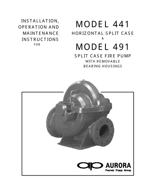
INSTALLATION,<br />
OPERATION AND<br />
MAINTENANCE<br />
INSTRUCTIONS<br />
FOR<br />
MODEL 441<br />
HORIZONTAL SPLIT CASE<br />
&<br />
MODEL <strong>491</strong><br />
SPLIT CASE FIRE PUMP<br />
WITH REMOVABLE<br />
BEARING HOUSINGS<br />
AURORA
TABLE OF CONTENTS<br />
PAGE i<br />
TOPIC<br />
PAGE<br />
PUMP IDENTIFICATION . . . . . . . . . . . . . . . . . . . . . . . . . . . . . . . . . . . . . . . 1<br />
STORAGE OF PUMPS . . . . . . . . . . . . . . . . . . . . . . . . . . . . . . . . . . . . . . . 2<br />
CAUTION NOTES . . . . . . . . . . . . . . . . . . . . . . . . . . . . . . . . . . . . . . . . . . 2<br />
INTRODUCTION. . . . . . . . . . . . . . . . . . . . . . . . . . . . . . . . . . . . . . . . . . . . 3<br />
INSTALLATION<br />
1. General . . . . . . . . . . . . . . . . . . . . . . . . . . . . . . . . . . . . . . . . . . . . 3<br />
2. Net Positive Suction Head (NPSH) . . . . . . . . . . . . . . . . . . . . . . . . . . . . . 3<br />
3. Minimum Submergence of Suction Pipe and Pit Design . . . . . . . . . . . . . . . . . . 4<br />
4. Location and Handling . . . . . . . . . . . . . . . . . . . . . . . . . . . . . . . . . . . . 4<br />
5. Foundation . . . . . . . . . . . . . . . . . . . . . . . . . . . . . . . . . . . . . . . . . . 4<br />
6. Leveling of Unit . . . . . . . . . . . . . . . . . . . . . . . . . . . . . . . . . . . . . . . . 4<br />
7. Grouting . . . . . . . . . . . . . . . . . . . . . . . . . . . . . . . . . . . . . . . . . . . 5<br />
8. Piping . . . . . . . . . . . . . . . . . . . . . . . . . . . . . . . . . . . . . . . . . . . . . 5<br />
9. Auxiliary Piping Connections and Gauges . . . . . . . . . . . . . . . . . . . . . . . . . 5<br />
10. Constant Level Oiler – Oil Lubricated Pumps . . . . . . . . . . . . . . . . . . . . . . . . 5-6<br />
11. Final Coupling Alignment . . . . . . . . . . . . . . . . . . . . . . . . . . . . . . . . . . 6-7<br />
12. Flexible Shaft Alignment . . . . . . . . . . . . . . . . . . . . . . . . . . . . . . . . . . 7<br />
13. Rotation . . . . . . . . . . . . . . . . . . . . . . . . . . . . . . . . . . . . . . . . . . . . 7<br />
14. Mechanical Seals . . . . . . . . . . . . . . . . . . . . . . . . . . . . . . . . . . . . . . . 8<br />
OPERATION<br />
1. Operating at Reduced Capacity . . . . . . . . . . . . . . . . . . . . . . . . . . . . . . . 9<br />
2. Priming . . . . . . . . . . . . . . . . . . . . . . . . . . . . . . . . . . . . . . . . . . . . 9<br />
3. Starting the Pump . . . . . . . . . . . . . . . . . . . . . . . . . . . . . . . . . . . . . . 10<br />
4. Bearing Operating Temperature . . . . . . . . . . . . . . . . . . . . . . . . . . . . . . . 10<br />
5. Troubleshooting Operating Problems . . . . . . . . . . . . . . . . . . . . . . . . . . . . 10<br />
MAINTENANCE<br />
1. Maintenance History . . . . . . . . . . . . . . . . . . . . . . . . . . . . . . . . . . . . . 11<br />
2. Inspections and Preventive Maintenance Requirements . . . . . . . . . . . . . . . . . 12<br />
3. Bearing Lubrication<br />
Grease-Lubricated Bearings . . . . . . . . . . . . . . . . . . . . . . . . . . . . . . . . 12<br />
Oil-Lubricated Bearings . . . . . . . . . . . . . . . . . . . . . . . . . . . . . . . . . . . 12-13<br />
4. Packing Box . . . . . . . . . . . . . . . . . . . . . . . . . . . . . . . . . . . . . . . . . 13<br />
5. Packing Replacement . . . . . . . . . . . . . . . . . . . . . . . . . . . . . . . . . . . . . 13-14<br />
6. Pump Disassembly . . . . . . . . . . . . . . . . . . . . . . . . . . . . . . . . . . . . . . 14-15<br />
7. Pump Assembly . . . . . . . . . . . . . . . . . . . . . . . . . . . . . . . . . . . . . . . . 16-18<br />
REPAIR PARTS . . . . . . . . . . . . . . . . . . . . . . . . . . . . . . . . . . . . . . . . . . . .<br />
19<br />
RECOMMENDED SPARE PARTS. . . . . . . . . . . . . . . . . . . . . . . . . . . . . . . . . . . 19<br />
NOTES . . . . . . . . . . . . . . . . . . . . . . . . . . . . . . . . . . . . . . . . . . . . . . . . . 20-22<br />
CROSS-SECTIONAL DRAWINGS AND PARTS LISTS . . . . . . . . . . . . . . . . . . . . . . . 23-24
PUMP IDENTIFICATION PAGE 1<br />
PUMP IDENTIFICATION<br />
Congratulations! You are the owner of one of the finest pumps commercially available. If you give it<br />
the proper care as outlined and recommended by this manual, it will provide you with reliable service<br />
and long life.<br />
441 & <strong>491</strong> SPLIT CASE PUMPS<br />
Your <strong>Aurora</strong> <strong>Model</strong> 441 & <strong>491</strong> is a Split Case Pump, meaning the casing is split along the horizontal<br />
centerline. This new compact design, with its shorter bearing span, has less deflection under<br />
hydraulic load which results in less wear on the sleeves, bearings and packing. It is ideally suited for<br />
applications such as water systems, boosters, liquid transfer, irrigation and Fire Protection Systems.<br />
These pumps are available with a wide variety of options including mechanical seals, impeller wear<br />
rings, oil-lubricated and water-cooled bearings. Some options may not be available on <strong>Model</strong> <strong>491</strong><br />
Fire Pumps.<br />
This manual applies to:<br />
X-441-XXX Horizontal Split Case Pumps with removable bearing housings<br />
X-<strong>491</strong>-XXX Horizontal Split Case Fire Pumps with removable bearing housings<br />
Example:<br />
4-<strong>491</strong>-11A<br />
Hydraulic design (if applicable)<br />
Maximum nominal impeller diameter<br />
Horizontal Fire Pump with removable bearing housings<br />
Discharge size<br />
Carefully record all the following data from your pump nameplate. It will aid in obtaining the correct<br />
replacement parts in the future.<br />
FIGURE (MODEL): __________________ SERIAL NUMBER: __________________<br />
IMPELLER DIAMETER:_______________ SIZE: _____________________________<br />
CAPACITY: _____________ GPM ______ TOTAL HEAD ____________ FT.<br />
RPM: __________________<br />
DRIVER<br />
HORSEPOWER: _______________ SERIAL NUMBER: _______________________<br />
SPEED: ____________ RPM VOLTAGE: _____________________________<br />
MANUFACTURER: _____________________ FRAME: ________________________
PAGE 2<br />
STORAGE OF PUMPS AND CAUTION NOTES<br />
THESE INSTRUCTIONS APPLY TO THE PUMP ONLY. THEY ARE INTENDED TO BE GENERAL<br />
AND NOT SPECIFIC. IF YOUR OPERATING CONDITIONS EVER CHANGE, ALWAYS REFER TO<br />
THE FACTORY FOR REAPPLICATION. ALWAYS REFER TO THE MANUALS PROVIDED BY<br />
MANUFACTURERS OF THE OTHER EQUIPMENT FOR THEIR SEPARATE INSTRUCTIONS.<br />
CAUTION<br />
IMPORTANT SAFETY NOTICE<br />
THE INSTALLATION, USE AND OPERATION OF THIS TYPE OF EQUIPMENT IS AFFECTED BY<br />
VARIOUS FEDERAL, STATE AND LOCAL LAWS AND THE REGULATIONS CONCERNING<br />
OSHA. COMPLIANCE WITH SUCH LAWS RELATING TO PROPER INSTALLATION AND SAFE<br />
OPERATION OF THIS TYPE OF EQUIPMENT IS THE RESPONSIBILITY OF THE EQUIPMENT<br />
OWNER AND ALL NECESSARY STEPS SHOULD BE TAKEN BY THE OWNER TO ASSURE<br />
COMPLIANCE WITH SUCH LAWS BEFORE OPERATING THE EQUIPMENT.<br />
STORAGE OF PUMPS<br />
IF THE EQUIPMENT IS NOT TO BE IMMEDIATELY INSTALLED AND OPERATED, STORE IT IN<br />
A CLEAN, DRY, WELL-VENTILATED PLACE, FREE FROM VIBRATION, MOISTURE AND RAPID<br />
OR WIDE VARIATIONS IN TEMPERATURE.<br />
SPECIAL INSTRUCTIONS FOR:<br />
OIL-LUBRICATED PUMPS: FILL THE BEARING RESERVOIRS WITH OIL. PRIOR TO<br />
START-UP, DRAIN THE STORAGE OIL AND FILL THE RESERVOIRS WITH NEW OIL.<br />
GREASE-LUBRICATED PUMPS: ROTATE THE SHAFT FOR SEVERAL REVOLUTIONS<br />
AT LEASE ONCE EVERY TWO WEEKS TO:<br />
1. COAT THE BEARING WITH LUBRICANT.<br />
2. RETARD OXIDATION OR CORROSION AND,<br />
3. PREVENT POSSIBLE FALSE BRINELLING.<br />
CONSIDER A UNIT IN STORAGE WHEN:<br />
1. IT HAS BEEN DELIVERED TO THE JOBSITE AND IS AWAITING INSTALLATION.<br />
2. IT HAS BEEN INSTALLED BUT OPERATION IS DELAYED PENDING COMPLETION OF<br />
CONSTRUCTION.<br />
3. THERE ARE LONG PERIODS (30 DAYS OR MORE) BETWEEN OPERATION CYCLES.<br />
4. THE PLANT (OR DEPARTMENT) IS SHUT DOWN FOR PERIODS OF LONGER THAN 30<br />
DAYS.<br />
NOTE:<br />
STORAGE REQUIREMENTS VARY DEPENDING ON THE LENGTH OF STORAGE,<br />
THE CLIMATIC ENVIRONMENT AND THE EQUIPMENT. FOR STORAGE<br />
PERIODS OF THREE MONTHS OR LONGER, CONTACT THE MANUFACTURER<br />
FOR SPECIFIC INSTRUCTIONS. IMPROPER STORAGE COULD DAMAGE THE<br />
EQUIPMENT WHICH WOULD RESULT IN NON-WARRANTY COVERED<br />
RESTORATION REQUIREMENTS OR NON-WARRANTY COVERED PRODUCT<br />
FAILURES.
INTRODUCTION AND INSTALLATION PAGE 3<br />
INTRODUCTION<br />
This manual contains information which is the result of carefully conducted engineering and research efforts. It<br />
is designed to supply adequate instructions for the safe and efficient installation, operation maintenance of your<br />
pump. Failure or neglect to properly install, operate or maintain your pump may result in personal injury,<br />
property damage or unnecessary damage to the pump.<br />
Variations exist in both the equipment used with these pumps and the particular installation of the pump and<br />
driver. Therefore, specific operating instructions are not within the scope of this manual. The manual contains<br />
general rules for installation, operation and maintenance of the pump.<br />
Observe all caution or danger tags attached to the pump or included in this manual.<br />
1. GENERAL<br />
CAUTION:<br />
INSTALLATION<br />
CAREFULLY READ ALL SECTIONS OF THIS MANUALAND ALL OTHER<br />
INSTRUCTION MANUALS PROVIDED BY MANUFACTURERS OF OTHER<br />
EQUIPMENT SUPPLIED WITH THIS PUMP.<br />
Upon receipt of the shipment, unpack and inspect the pump and driver assemblies and individual parts to<br />
ensure that none are missing or damaged. Carefully inspect al boxes and packing material for loose parts<br />
before discarding them. Report immediately to the transportation company involved, and to the factory, any<br />
missing parts or damage incurred during shipment, and file your “damaged and/or lost-in-shipment” claim with<br />
the carrier.<br />
Horizontal pump and driver assemblies mounted on a common base are accurately aligned at the factory.<br />
However, alignment may be disturbed in transit or during installation. It must be checked after the unit is<br />
leveled on its foundation, after the grouting has set and the foundation bolts are tightened, and after the piping<br />
is completed.<br />
When the pump and driver are mounted on separate base structures, the pump should be leveled and aligned<br />
first, then the driver leveled and aligned with the pump. With separate bases, a flexible shaft between the pump<br />
and driver must be used.<br />
2. NET POSITIVE SUCTION HEAD (NPSH)<br />
NPSH can be defined as the head (energy) that causes liquid to flow through the suction pipe and enter the eye<br />
of the impeller.<br />
NPSH is expressed in two values: (1) NPSH required (NPSH R ) and (2) NPSH available (NPSH A ). It is essential<br />
that NPSH A be always greater than NPSH R to prevent cavitation, vibration, wear and unstable operation.<br />
NPSH R is a function of the pump design and therefore varies with the model, size, capacity and speed of the<br />
pump. The value for your pump can be obtained from your pump performance curve or from the factory.<br />
A. When the source of the liquid is above the pump:<br />
NPSH A = barometric pressure (feet) + static suction head (feet) – friction losses in suction piping<br />
(feet) – vapor pressure of liquid (feet)<br />
B. When the source of the liquid is below the pump:<br />
NPSH A = barometric pressure (feet) - static suction lift (feet) – friction losses in suction piping (feet)<br />
– vapor pressure of liquid (feet)
PAGE 4<br />
INSTALLATION (continued)<br />
3. MINIMUM SUBMERGENCE OF SICTION PIPE AND PIT DESIGN<br />
For installations where the pump draws fluid from a sump, the hydraulic characteristics of the pump, the suction<br />
inlet submergence and NPSH must be considered. Generally, it is required that an evenly distributed flow of<br />
non-aerated water be supplied to the suction bell. Improper pit design or insufficient suction pipe submergence<br />
can result in intake vortexing which reduces the pump’s performance and can result in severe damage to the<br />
pump.<br />
We recommend that you secure the advice of a qualified Consulting Engineer for the analysis of the suction pit.<br />
Significant engineering data on design is provided in the Hydraulic Institute Standards.<br />
4. LOCATION AND HANDLING<br />
The pump should be located as near the fluid as possible so a short direct suction pipe can be used to keep<br />
suction losses at a minimum. If possible, locate the pump so the fluid will flow to the suction opening by gravity.<br />
The discharge piping should be direct and with as few elbows and fittings as possible. The total net positive<br />
suction head available (NPSH A ), which includes suction lift and pipe friction losses, must be equal to or greater<br />
than the net positive suction head required (NPSH R ) by the pump.<br />
The pump and driver should be located in an area that will permit periodic inspection and maintenance. Head<br />
room and access should be provided and all units should be installed in a dry location with adequate drainage.<br />
WARNING: DO NOT LIFT THE COMPLETE UNIT BY THE DRIVER OR PUMP SHAFTS OR EYE BOLTS.<br />
To lift a horizontal mounted unit, a chain or suitable lifting device should be attached to each corner of the unit<br />
base. The driver by itself may be lifted using the proper eyebolts provided by the manufacturer, but these<br />
should not be used to lift the entire assembled unit.<br />
5. FOUNDATION<br />
The foundation should have a level surface and have sufficient mass to prevent vibration and form a permanent<br />
rigid support for the unit. The most satisfactory foundations are concrete with anchor bolts of adequate size<br />
embedded in the foundation in pipe sleeves with an inside diameter 2½ times larger than the bolt diameter.<br />
This will allow final accurate positioning of the unit.<br />
6. LEVELING OF THE UNIT<br />
Lower the unit onto the foundation, positioning it so the anchor bolts are aligned with the center of the mounting<br />
holes in the base. On all units, always disconnect the coupling halves and never reconnect them until all the<br />
alignment operations are complete.<br />
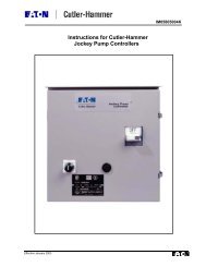
The base should be supported on metal shims or metal wedges placed directly under the part of the base<br />
carrying the greatest weight, and spaced close enough to give uniform support and stability (see Figure 1).<br />
Adjust the metal shims or wedges until the shafts of the pump and driver are level. Alignment adjustments can<br />
be accomplished by adjusting the supports under the base. When proper alignment is obtained, tighten the<br />
foundation bolts snugly, but not too firmly, and recheck the alignment before grouting.<br />
Figure 1<br />
BASEPLATE INSTALLATION
7. GROUTING<br />
INSTALLATION (continued) PAGE 5<br />
When the alignment is correct, the unit should be grouted using high grade non-shrinking grout. The entire<br />
base should be filled with grout. Be sure to fill all gaps and voids. Allow the grout to fully cure before firmly<br />
tightening the foundation bolts. Then recheck the alignment before connecting the piping.<br />
8. PIPING<br />
CAUTION:<br />
CAUTION:<br />
ALL PIPING CONNECTIONS MUST BE MADE WITH THE PIPING IN A FREE<br />
SUPPORTED STATE, AND WITHOUT THE NEED TO APPLY VERTICAL OR<br />
SIDE PRESSURE TO OBTAIN ALIGNMENT OF THE PIPING WITH THE<br />
PUMP FLANGE.<br />
AFTER ALL THE PIPING IS CONNECTED, THE PUMP AND DRIVER<br />
ALIGNMENT MUST BE RECHECKED.<br />
All piping should be independently supported near the pump so that pipe strain will not be transmitted to the<br />
pump casing. The suction and discharge piping should be one or two sizes larger than the pump flange sizes,<br />
especially where the piping is of considerable length. Any flexible joints installed in the piping must be equipped<br />
with tension rods to absorb piping axial thrust. Care must be exercised in arranging elbows so as not to<br />
generate vortexing in the pump inlet.<br />
The suction pipe must be air tight and sloped upward to the pump flange to avoid air pockets which will impair<br />
satisfactory pump operation. The discharge pipe should be as direct as possible with a minimum of valves to<br />
reduce pipe friction losses.<br />
A check valve and closing valve should be installed in the pump discharge line and a closing valve in the<br />
suction line. The check valve, between the pump and the closing valve, protects the pump from water hammer<br />
and prevents reverse rotation in the event of power failure. The closing valves are used in priming, starting and<br />
when the pump is shut down. The pump must never be throttled by the use of a valve in the suction line.<br />
9. AUXILIARY PIPING CONNECTIONS AND GAUGES<br />
In addition to the primary piping connections, your pump may require mechanical seal and seal water filter<br />
connections, connections to the lantern ring (see the “Packing Box” and “Mechanical Seal” sections of this<br />
manual), stuffing box drain, discharge and suction flange gauges, casing relief valve drain or baseplate drain<br />
connections. All these lines and gauges should now be installed.<br />
10. CONSTANT LEVEL OILERS<br />
If your pump has oil-lubricated bearings, it will be equipped with constant level oilers which will be shipped loose<br />
to prevent damage in shipment. The oilers must be installed in the tapped holes in the side of the beating<br />
housings. To provide proper lubrication, the pipe connection the oiler to the bearing housing must be level (see<br />
Figure 2).<br />
FIGURE 2<br />
When the oiler is level, fill the bottle and screw it onto the lower reservoir of the oiler. Allow the oil to flow into<br />
the bearing reservoir. Several fillings of the bottle may be required before the oil level for which the oiler is set is<br />
reached and the oil stops flowing. After filling the oil reservoir, check the oil level to make sure it is as specified<br />
in the following table (see Page 6).
PAGE 6<br />
INSTALLATION (continued)<br />
BEARING HOUSING OIL LEVEL CHART<br />
4-441-11A/C 5-441-18A 5-441-11A<br />
PUMP MODEL 3-441-9A/C 4-441-14C 6-441-14A/C 6-441-19A<br />
2-441-8A<br />
(PUMP SIZE) 4-441-8A 5-441-14A 6-441-18C 8-441-18A<br />
6-441-12A 8-441-14A 10-441-20<br />
Centerline of shaft to oil level 3/4" 7/8" 1-3/16" 1-1/2" 1-13/16"<br />
NOTE: For Fire Pumps, the <strong>Model</strong> designation changes from “441” to “<strong>491</strong>.”<br />
Adjust the oil level, if necessary, by loosening the setscrews on the side of the dust cap, raising the bottle and<br />
tightening the screws. Refer to the oiler manufacturer’s instructions for more specific details.<br />
11. FINAL COUPLING ALIGNMENT<br />
The alignment of the coupling must be carefully checked during installation and as the last step before starting<br />
the pump. If realignment is required, the piping should be disconnected first. After aligning, reconnect the<br />
piping in accordance with the previous instructions and again recheck the alignment.<br />
A flexible coupling must not be used to compensate for misalignment resulting from poor installation or<br />
temperature changes.<br />
<strong>Aurora</strong> Pumps are supplied with several different types of commercial couplings. The following instructions<br />
apply to units supplied with Woods couplings. If your unit has a different brand coupling, the manufacturer’s<br />
instructions should be obtained before proceeding.<br />
NOTE: FOR MAXIMUM LIFE, KEEP MISALIGNMENT VALUES AS NEAR TO ZERO AS POSSIBLE.<br />
MAXIMUM ALLOWABLE MISALIGNMENT – WOODS COUPLINGS (Dimensions in inches)<br />
Sleeve Types E & N Type H<br />
"G" Dimension<br />
Size Parallel Angular Parallal Angular<br />
4 1/2 .005 .021 - -<br />
5 3/4 .007 .028 - -<br />
6 7/8 .007 .035 .005 .008<br />
7 1 .010 .040 .006 .010<br />
8 1-1/8 .010 .047 .007 .012<br />
9 1-7/16 .012 .054 .008 .014<br />
10 1-5/8 .012 .064 .010 .016<br />
11 1-7/8 .016 .075 .011 .018<br />
12 2-5/16 .016 .087 .012 .021<br />
13 2-11/16 .020 .092 .015 .025<br />
14 3-1/4 .022 .121 .017 .030<br />
16 4-1/4 .031 .165 - -<br />
The coupling Type is printed on the sleeve.<br />
* Type H sleeves SHOULD NOT be used as direct replacements for EPDM or Hytrel sleeves.<br />
A. Use a blunt screwdriver to slip the wire ring out of the groove and remove the two-piece sleeve.<br />
Check the “G” dimension. If it is not as shown in the preceding table, loosen one flange of the<br />
coupling and reposition it to achieve the specified “G” dimension.<br />
NOTE: On a sleeve bearing electric motor, the armature should be at its electrical center when the “G”<br />
dimension is measured.<br />
B. Check parallel misalignment by placing a straightedge across the two coupling flanges and<br />
measuring the maximum offset at various points around the periphery of the coupling. DO NOT<br />
ROTATE THE COUPLING. If the maximum offset exceeds the figure shown under “Parallel” in the<br />
preceding table, realign the coupling.
INSTALLATION (continued) PAGE 7<br />
FIGURE 3<br />
COUPLING ALIGNMENT<br />
11. FINAL COUPLING ALIGNMENT (continued)<br />
C<br />
Check the angular alignment with a micrometer or caliper. Measure from the outside of one flange to<br />
the outside of the other at intervals around the periphery of the coupling. Determine the maximum<br />
and minimum dimensions. DO NOT ROTATE THE COUPLING. The difference between the<br />
maximum and minimum dimensions should not exceed the figure shown under “Angular” in the<br />
preceding table. If a correction is required, you must always recheck the parallel alignment.<br />
D. If the coupling employs a two-piece sleeve with a wire ring, force the ring into its groove in the center<br />
of the sleeve. It may be necessary to pry the ring into position with a blunt screwdriver.<br />
WARNING:<br />
WARNING:<br />
12. FLEXIBLE SHAFTING ALIGNMENT<br />
CHECK SAFETY CODES, AND ALWAYS INSTALL PROTECTIVE GUARD OR<br />
SHIELD AS REQUIRED BY VARIOUS FEDERAL, STATE AND LOCAL LAWS AND<br />
REGULATIONS CONCERNING OSHA.<br />
COUPLING SLEEVES MAY BE THROWN FROM THE ASSEMBLY WHEN<br />
SUBJECTED TO A SEVERE SHOCK LOAD.<br />
For installation and alignment of intermediate flexible shafting, refer to the manufacturer’s instructions.<br />
13. ROTATION<br />
Before connecting the coupling halves, bump start the driver to verify rotation is in the proper direction. The<br />
correct pump rotation is indicated by a directional arrow on the pump casing.
PAGE 8<br />
INSTALLATION continued)<br />
14. MECHANICAL SEALS<br />
CAUTION: DRY OPERATION OF THE PUMP MAY CAUSE DAMAGE TO THE MECHANICAL SEAL<br />
AND IMPELLER.<br />
<strong>Model</strong> 441 pumps can be supplied with optional single face mechanical shaft seals. Mechanical seals are<br />
installed and adjusted in the factory and require no further adjustments in the field.<br />
For further information, refer to the seal manufacturer’s instructions.<br />
FIGURE 4<br />
TYPICAL MECHANICAL SEAL
OPERATION PAGE 9<br />
Because variations exist in both the equipment used with these pumps and in the particular installation of the<br />
pump and driver, specific operating instructions are not within the scope of this manual. However, there are<br />
general rules and practices that apply to all pump installations and operation.<br />
CAUTION: BEFORE STARTING OR OPERATING THE PUMP, READ THIS ENTIRE MANUAL,<br />
ESPECIALLY THE FOLLOWING INSTRUCTIONS:<br />
A. BEFORE STARTING THE PUMP, INSTALL CLOSED GUARDS AROUND THE COUPLING.<br />
B. BEFORE STARTING THE PUMP, ROTATE THE UNIT OR ASSEMBLY BY HAND TO ASSURE ALL<br />
MOVING PARTS ARE FREE.<br />
C. OBSERVE ALL CAUTION AND DANGER TAGS ATTACHED TO THE EQUIPMENT.<br />
D. NEVER RUN THE PUMP DRY AS THE CLOSE RUNNING FITS WITHIN THE PUMP ARE WATER<br />
LUBRICATED. RUNNING DRY MAY RESULT IN PUMP SEIZURE.<br />
E. BEFORE STARTING THE PUMP, FILL THE CASING AND SUCTION LINE WITH LIQUID. THE<br />
PUMP MAY BE PRIMED USING AN EJECTOR OR VACUUM PUMP.<br />
F. BEFORE STARTING A PACKED BOX PUMP, ADJUST THE PACKING GLAND SO THERE IS<br />
SUFFICIENT LEAKAGE TO LUBRICATE THE PACKING AND ASSURE A COOL PACKING BOX.<br />
(SEE MAINTENANCE INSTRUCTIONS).<br />
G. IF EXCESSIVE VIBRATION OR NOISE OCCURS DURING OPERATION, SHUT THE PUMP DOWN<br />
AND CONSULT AN AURORA PUMP REPRESENTATIVE.<br />
1. OPERATING AT REDUCED CAPACITY<br />
Although these pumps are applicable over a wide range of operating conditions, care should be exercised when<br />
doing so, especially when the actual conditions differ from the sold-for conditions. You should always contact<br />
your nearest <strong>Aurora</strong> Pump sales office before operating the pumps for any condition other than that for which it<br />
was sold.<br />
2. PRIMING<br />
Since the pump medium is used to lubricate various internal parts, running a centrifugal pump dry can result in<br />
extensive damage and possible seizing. It is therefore imperative that the pump be primed prior to initial startup<br />
and that prime be maintained through subsequent start-stop cycles.<br />
The priming method is different for positive and negative suction head systems, and the following procedures<br />
should be followed.<br />
A. Positive Suction Head –<br />
1. Open the vent on the highest point on the pump casing.<br />
2. Open all suction valves.<br />
3. Allow the pumped liquid to flow from the vent hole until all air bubbles are vented, then close the<br />
vent.<br />
4. The pump is now primed.<br />
B. Negative Suction Head –<br />
1. Install an ejector or vacuum pump on the vent at the highest point on the pump casing.<br />
2. Close the discharge valve.<br />
3. Open the suction valve.<br />
4. Start ejector or vacuum pump.<br />
5. Allow the liquid to flow until a continuous flow is exhausted from the ejector, then close the valve to<br />
the vent.<br />
6. The pump is now primed.
PAGE 10<br />
OPERATION (continued)<br />
3. STARTING THE PUMP<br />
A. After the pump is primed, and with the discharge valve closed and the suction valve open, start the driver<br />
according to the driver manufacturer’s instructions.<br />
B. Open the discharge valve slowly to prevent water hammer.<br />
C. After the pump has been started, check bearing temperatures, packing box lubrication and operation and<br />
pump noise level for a period of several hours.<br />
CAUTION: BEGIN THESE CHECKS IMMEDIATELY UPON STARTING THE PUMP AND MONITOR<br />
THEM CONTINUOUSLY FOR THE FIRST SEVERAL HOURS OF OPERATION.<br />
4. BEARING OPERATING TEMPERATURE<br />
These pumps are designed to operate over a wide ambient temperature range. The bearing temperature, when<br />
measured at the outside surface of the bearing housing, should not exceed 190 o F. Temperatures in excess of<br />
190 o F may indicate lack of lubricant, bearing overload or insipient bearing failure. If the temperature exceeds<br />
this limit, the pump should be stopped and the cause investigated and corrected.<br />
5. TROUBLESHOOTING OPERATING PROBLEMS<br />
If you have followed the installation and start-up procedures outlined in this manual, your pump should provide<br />
reliable service and long life. However, if operating problems do occur, significant time and expense can be<br />
saved if you use the following checklist to eliminate the most common causes of those problems.<br />
INSUFFICIENT DISCHARGE<br />
PRESSURE OR FLOW<br />
1. Pump not primed.<br />
2. Speed too slow; check driver.<br />
3. Discharge head too high.<br />
4. Suction lift too high.<br />
5. Wrong direction of rotation<br />
6. Air leaks into suction piping, packing box or<br />
gaskets.<br />
7. Impeller passage partially plugged.<br />
8. Impeller damaged.<br />
9. Impeller running clearance too large.<br />
10. Insufficient suction line submergence.<br />
11. Air in liquid.<br />
12. Impeller diameter too small.<br />
13. Insufficient Net Positive Suction Head.<br />
LOSS OF SUCTION DURING OPERATION<br />
1. Suction line leaks.<br />
2. Water seal line plugged.<br />
3. Suction lift too high.<br />
4. Air or gases in liquid.<br />
5. Air leaks into suction piping, packing box or<br />
gaskets.<br />
6. Wrong direction of rotation.<br />
7. Insufficient suction line submergence.<br />
EXCESSIVE POWER CONSUMPTION<br />
1. Speed too high.<br />
2. Head lower than rating, pumping too much liquid.<br />
3. Specific gravity or viscosity of liquid too high.<br />
4. Mechanical defects:<br />
• Shaft bent<br />
• Rotating element binds<br />
5. Misalignment.<br />
6. System head lower than design.<br />
7. Incorrect impeller diameter.<br />
VIBRATION OR NOISE<br />
1. Misalignment between driver and pump.<br />
2. Loose foundation bolts or defective grouting.<br />
3. Mechanical defects:<br />
• Shaft bent<br />
• Rotating element binds<br />
4. Head lower than rating; pumping too much liquid.<br />
5. Pipe strain – improperly supported or aligned.<br />
6. Pump running at shut-off condition.<br />
7. Insufficient suction line submergence.<br />
8. Air in liquid.<br />
OVERHEATING<br />
1. Bearings:<br />
• Excessive grease.<br />
• Shaft bent.<br />
• Rotating element binds.<br />
• Pipe strain.<br />
• Insufficient bearing lubrication.<br />
• Incorrect type grease<br />
2. Packing box:<br />
• Packing gland too tight.<br />
• Water seal line plugged<br />
• Air not vented out of mechanical seal.<br />
• Flushing water not circulating for mechanical<br />
seal.
MAINTENANCE PAGE 11<br />
1. MAINTENANCE HISTORY<br />
DATE MAINTENANCE PERFORMED PARTS USED<br />
SYMBOL<br />
NUMBER(S)
PAGE 12<br />
MAINTENANCE (continued)<br />
2. INSPECTIONS AND PREVENTIVE MAINTENANCE REQUIREMENTS<br />
To assure satisfactory operation of the pump, daily inspections and periodic maintenance are required. We<br />
suggest that an inspection and maintenance log be kept and that the inspector immediately report any<br />
problems. A guide for preventive maintenance for normal applications is given below. Unusual applications,<br />
with abnormal heat, moisture, dust, etc. may require more frequent inspections and service.<br />
ITEM<br />
Packing Box<br />
Pump Alignment<br />
Vibration<br />
Bearings:<br />
Grease lubricated<br />
Oil lubricated<br />
ACTION REQUIRED<br />
Adjust gland, inspect packing for<br />
possible replacement<br />
Check for change in alignment<br />
Check for change in vibration<br />
Lubricate<br />
FREQUENCY (HOURS OF OPERATION)<br />
150 Hours<br />
ANNUALLY<br />
ANNUALLY<br />
Every 2000 hours of operation,<br />
but at least once a year.<br />
As required to maintain proper oil level –<br />
drain and replace oil every 2000 hours of<br />
operation, but at least once a year.<br />
3. BEARING LUBRICATION<br />
A. Grease Lubricated Bearings<br />
Under normal operating conditions, the bearings must be lubricated after every 2000 hours of running<br />
time, but at least once a year regardless of total operating hours.<br />
CAUTION:<br />
CAUTION:<br />
ANY APPLICATION WITH ABNORMAL HEAT, MOISTURE, DUST, ETC. MAY<br />
REQUIRE A CHANGE IN THIS SCHEDULE AND YOU SHOULD REFER TO A<br />
LUBRICATION ENGIEER OR THE FACTORY FOR SPECIFIC INSTRUCTIONS.<br />
THE GREASES RECOMMENDED IN THIS MANUAL WILL PROVIDE SATISFACTORY<br />
LUBRICATION OVER A WIDE TEMPERATURE RANGE. THERE IS, HOWEVER, A<br />
PRACTICAL LIMIT, AND OPERATION OF THE PUMP SHOULD BE DISCONTINUED<br />
AND THE FACTORY CONSULTED IF THE TEMPERATURE, WHEN MEASURED ON<br />
THE OUTSIDE OF THE BEARING HOUSING, EXCEEDS 190 o F.<br />
RECOMMENDED GREASE: Chevron SRI grease N.L.G.I. No. 2 multi-purpose with a mineral oil<br />
viscosity of 517 SUS at 100 o F or equivalent.<br />
Proceed as follows for bearing lubrication:<br />
WARNING:<br />
KEEP HANDS, FINGERS, CLOTHING AND ANY TOOLS AWAY FROM THE<br />
COUPLING. FAILURE TO DO SO COULD RESULT IN SERIOUS PERSONAL<br />
INJURY.<br />
1. Stop the pump and remove the pipe plug at the bottom of the bearing housing.<br />
2. Connect a grease gun to the lubrication fitting.<br />
3. Inject grease until it relieves at the bearing housing cover and drain hole.<br />
4. Remove the grease gun.<br />
5. Start the pump. NOTE: Immediately after lubrication, bearing temperatures may rise above the<br />
normal level. Continue running the unit until bearing temperatures stabilize at the normal level.<br />
6. Stop the unit, wipe off the relieved grease and replace the drain plug.<br />
7. Start the unit and resume normal operation.<br />
B. Oil Lubricated Bearings<br />
Fill the constant level oiler and add additional oil as required. Replace the old oil with new every 2000<br />
hours, but at least once a year. Drain the oil by removing the plug at the bottom of the bearing<br />
housings (C158 and D158).
3. BEARING LUBRICATION (continued)<br />
MAINTENANCE (continued) PAGE 13<br />
Check the oiler setting periodically to be sure it is correct. Refer to the following table for the correct setting.<br />
RECOMMENDED OILS: The oil used should be non-detergent type containing rust and oxidation inhibitors,<br />
supplied by a reputable manufacturer.<br />
Depending on bearing/pump operating temperature, the grade and viscosity should be as follows:<br />
Below 120 o F – ISO Vg Grade 40-70 (SAE 20)<br />
120F to 250 o F – ISO Vg Grade 70-100 (SAE 20)<br />
Above 250 o F – Consult the factory for a recommendation.<br />
4. PACKING BOX<br />
CAUTION: DO NOT TIGHTEN THE GLAND TO STOP ALL LEAKAGE. LEAKAGE IS NECESSARY TO<br />
ENSURE THE COOLING, FLUSHING AND LUBRICATION OF THE PACKING AND TO<br />
PREVENT SHAFT SLEEVE DAMAGE.<br />
The packing boxes on <strong>Aurora</strong> Pumps are packed at he factory. All packing is subject to wear and should be<br />
given regular inspections and, if necessary, periodic adjustments. Generally, packed box pumps require<br />
inspection of the packing and adjustments to the glands after each 150 hours of operation.<br />
Adjustment is made by lightly tightening the gland nuts, then loosening them so that they can be adjusted with<br />
finger pressure to allow a small flow of liquid to lubricate the packing. If the flow of liquid has increased and<br />
cannot be reduced by a slight tightening of the gland, add one ring of packing to the packing box and readjust<br />
the gland. If this fails to reduce the flow, replace the packing and/or shaft sleeve.<br />
The packing boxes may be fitted with lantern rings. When a lantern ring is furnished, the sealing chamber<br />
should be connected to a source of clear fresh water.<br />
5. PACKING REPLACEMENT<br />
Use a good grade of soft, square long fiber packing, thoroughly graphited. The replacement procedure should<br />
be as follows:<br />
A. Stop the pump.<br />
B. Unbolt and remove the glands away from the packing.<br />
C. Use a packing hook to remove the worn rings of packing and lantern rings. Note the location of the<br />
lantern rings relative to the amount of packing on each side of the lantern rings. (See sectional<br />
drawings on pages 23 & 24.)<br />
D. Clean the packing boxes and shaft sleeves.<br />
E. Inspect the shaft sleeves for wear or rough finish and replace if necessary.<br />
F. Install new packing and lantern rings.<br />
CAUTION:<br />
STAGGER THE PACKING END JOINTS 180 AND FIRMLY SEAT THE PACKING.<br />
THE FOLLOWING TABLE GIVES THE PERTINENT PACKING BOX, LANTERN RING<br />
AND PACKING DIMENSIONS (see page 14).<br />
G. Reinstall the glands and tighten the gland nuts.<br />
H. Loosen the gland nuts so they can be adjusted with finger pressure to obtain correct leakage for<br />
lubrication after start-up.
PAGE 14<br />
MAINTENANCE (continued)<br />
5. PACKING REPLACEMENT (continued)<br />
PUMP MODEL (PUMP SIZE)<br />
4-441-11A 5-441-18A<br />
2-441-8A 3-441-9A/C 4-441-14C 6-441-14A/C 6-441-19A<br />
4-441-8 5-441-14A 6-441-18A 10-441-20<br />
6-441-12A 8-441-14A<br />
PACKING BOX<br />
Sleeve O.D. 1-5/8 2 2-1/2 3 3-1/2<br />
Packing Box I.D. 2-7/16 2-15/16 3-9/16 4-3/16 4-13/16<br />
Packing Box Depth 2-15/16 2-7/8 3-7/8 4-5/16 4-3/4<br />
PACKING SIZE 3/8 3/8 1/2 9/16 5/8<br />
Qty. of Rings per Box<br />
(Without Lantern Ring)<br />
Lantern Ring Width 3/4 3/4 1 1-1/8 1-1/4<br />
PACKING ARRANGEMENT<br />
WITH LANTERN RING<br />
(Packing Rings-Lantern<br />
Ring-Packing Ring)*<br />
7 7<br />
7 7 7<br />
2-L-3 2-L-3 2-L-3 2-L-3 2-L-3<br />
* See Sectional Drawings on pages 23 & 24.<br />
NOTE: For Fire Pumps, the <strong>Model</strong> designation changes from “441” to “<strong>491</strong>.”<br />
6. PUMP DISASSEMBLY<br />
CAUTION:<br />
READ THIS ENTIRE DISASSEMBLY PROCEDURE AND REFER TO THE SECTIONAL<br />
DRAWINGS IN THIS MANUAL BEFORE PROCEEDING.<br />
Major maintenance will require disassembly of the pump. Following are step-by-step instructions.<br />
A. Lock out the power to the driver and close the suction and discharge valves. Drain the pump,<br />
disconnect and remove the coupling or flexible shafting. Disconnect and remove all auxiliary piping to<br />
the upper casing (3) and bearing housings (C158 and D158) (packing box flush line, lubricators on oil<br />
lubricated pumps, cooling water lines on pumps with water-cooled bearings, etc.).<br />
B. Remove the capscrews (2A) securing the upper casing half (3) to the lower half (2). Remove the gland<br />
nuts (31B) and slide the glands (A31 or B31) off the gland studs (31A). Install jack screws in the tapped<br />
holes in the upper casing half and use them to separate the flanges. Carefully lift the upper casing half<br />
using the long shank eyebolts in the tapped holes in the upper casing half.<br />
CAUTION: USE OF A CRANE OR HOIST OF ADEQUATE CAPACITY IS RECOMMENDED. THE<br />
LIFTING HOOK SHOULD BE NO LESS THAN 3-4 FEET ABOVE THE EYE OF THE<br />
EYEBOLTS TO AVOID BENDING OF THE BOLTS. THE USE OF THE SHORT<br />
EYEBOLTS IS NOT RECOMMENDED SINCE THE UPPER CASING HALF WILL TEND<br />
TO TIP WHILE BEING LIFTED, RESULTING IN POSSIBLE DAMAGE OR PERSONAL<br />
INJURY.<br />
C. Remove the capscrews (158B) and pins (158A) that secure the bearing housings (158) to the lower<br />
casing. The pins may be removed using the threaded holes in the pins.<br />
D. Lift the rotor assembly from the casing using a double rope sling.<br />
WARNING:<br />
BE CAREFUL WHEN POSITIONING THE ROPES TO AVOID THE ROTOR SLIPPING<br />
AND CAUSING POSSIBLE SERIOUS PERSONAL INJURY.
MAINTENANCE (continued) PAGE 15<br />
6. PUMP DISASSEMBLY (continued)<br />
E. Remove the capscrews (159D) that secure the bearing housing covers (159) to the bearing housings<br />
and remove the housings from the rotating assembly.<br />
F. Remove the outer snap ring (345) from the outboard bearing end of the rotating assembly, and use a<br />
wheel/bearing puller to remove the outboard (168) and inboard (163) bearings.<br />
WARNING:<br />
CAUTION:<br />
TO PREVENT POSSIBLE SERIOUS PERSONAL INJURY, EXTREME CARE SHOULD<br />
BE EXERCISED TO SELECT THE PROPER PULLER, AND APPROVED SAFETY<br />
GLASSES SHOULD BE WORN.<br />
BECAUSE OF POSSIBLE DAMAGE OR CONTAMINATION DURING REMOVAL,<br />
BEARINGS SHOULD NOT BE REUSED AND NEW BEARINGS SHOULD ALWAYS<br />
BE INSTALLED.<br />
G. Remove bearing housing covers (159), water slingers (126), casing wearing rings (16), lantern rings<br />
(10) and packing (212). If the pump is equipped with mechanical seals (456), refer to the seal<br />
manufacturer’s instructions.<br />
If the pump is equipped with an oil lubrication system, remove the lip seals (158C) from the inboard and<br />
outboard bearing housing covers and the inboard bearing housing.<br />
H. Remove the shaft sleeves (A14 or B14). Depending on the pump service, shaft sleeves are supplied in<br />
two different configurations. The removal procedure for each configuration differs:<br />
Sleeves Affixed With Loctite: Remove the shaft sleeve nuts (213) (if they are provided), heat the<br />
sleeves to approximately 450 o F to break the bond, then tap them with a brass or copper mallet.<br />
WARNING:<br />
TO PREVENT POSSIBLE SERIOUS PERSONAL INJURY, HEAT RESISTANT<br />
GLOVES MUST BE WORN WHEN HANDLING HEATED PARTS.<br />
Sleeves Keyed To Shaft: Remove the shaft sleeve nuts (213), shaft sleeves (B14) and the shaft<br />
sleeve O-rings (452).<br />
CAUTION: BECAUSE OF POSSIBLE DAMAGE DURING DISASSEMBLY, O-RINGS SHOULD NOT<br />
BE REUSED AND NEW O-RINGS SHOULD ALWAYS BE INSTALLED.<br />
I. Slide the impeller (1) off the shaft (4) and remove the impeller key (102).<br />
J. If your pump has impeller wear rings and they require replacement, they will be secured by one of two<br />
methods, and you should proceed as follows:<br />
Wearing Rings Secured With Loctite: Heat the sleeves to approximately 450 o F to break the bond,<br />
then tap them with a brass or copper mallet. If heating fails to affect removal, the rings may be ground<br />
off.<br />
Wearing Rings Secured With Setscrews: Remove the setscrews (17A) and chisel cut or grind the<br />
rings in two at the setscrew location.<br />
WARNING:<br />
WARNING:<br />
TO PREVENT POSSIBLE SERIOUS PERSONAL INJURY, HEAT RESISTANT<br />
GLOVES MUST BE WORN WHEN HANDLING HEATED PARTS.<br />
TO PREVENT POSSIBLE SERIOUS PERSONAL INJURY, EXTREME CARE SHOULD<br />
BE EXERCISED TO SELECT THE PROPER GRINDING EQUIPMENT, AND<br />
APPROVED SAFETY GLASSES SHOULD BE WORN WHEN GRINDING.<br />
K. The pump disassembly is now complete. All parts should be thoroughly cleaned and inspected for<br />
wear or damage, and replaced if required.
PAGE 16<br />
MAINTENANCE (continued)<br />
7. PUMP ASSEMBLY<br />
CAUTION:<br />
READ THIS ENTIRE PROCEDURE BEFORE CONTINUING.<br />
Following are step-by-step instructions for assembly of the pump and are essentially the reverse order of the<br />
instructions for disassembly.<br />
A. Thoroughly clean all parts to remove oil, grease and foreign material. Inspect for wear or damage and<br />
replace if required. Remove all parts to a clean and dust-free location for assembly. Gaskets, grease<br />
seals and bearings should not be reused and should always be replaced with new parts.<br />
B. If the impeller wear rings (17) require replacement, they are a light press fit and will be secured by one<br />
of the following methods. You should proceed as follows:<br />
Rings Secured With Loctite: Apply a light film of Loctite No. 290 to the impeller part of the<br />
impeller/wear ring fit and install the rings.<br />
Rings Secured With Set Screws: Press the rings in place and drill and tap them using the same size<br />
and number of setscrews as originally provided. The new holes should be 15 o to 20 o from the old<br />
holes. Install and tighten the set screws.<br />
CAUTION: BE CAREFUL NOT TO DRILL THROUGH THE IMPELLER AND BE SURE TO PRESS<br />
THE WEAR RING COMPLETELY IN PLACE. THEY SHOULD BE FIRMLY BUTTED<br />
AGAINST THE CORRESPONDING IMPELLER SHOULDER.<br />
C. Install the impeller key (102) in the shaft (4) and slide the impeller (1) over the key, centering it between<br />
the shaft shoulders as shown in Figure 5.<br />
FIGURE 5<br />
CAUTION: IF THE SHAFT SLEEVES ON YOUR PUMP ARE SECURED WITH LOCTITE ONLY,<br />
REFER TO THE SHAFT SLEEVE INSTALLATION INSTRUCTIONS BEFORE<br />
INSTALLING THE IMPELLER.<br />
D. Install the shaft sleeves (A14 or B14), shaft sleeve nuts (213) and O-rings (452), if your pump uses<br />
them, on the shaft. The shaft sleeves will be secured by one of three methods and you should proceed<br />
as follows:<br />
Sleeves Secured With Loctite And Sleeve Nuts: Apply two beads of Loctite No. 601 around the<br />
shaft on the shaft/shaft sleeve fit, one approximately 2 inches from the impeller hub and the second at<br />
the threaded end. Slide the shaft sleeves part way onto the shaft and rotate them at least one full<br />
revolution to evenly spread the Loctite, then slide the sleeves over the shaft until they butt firmly against<br />
the impeller hub. Install and tighten the shaft sleeve nuts (213) and the set screws (213A).
7. PUMP ASSEMBLY (continued)<br />
MAINTENANCE (continued) PAGE 17<br />
Sleeves Secured With Loctite Only: Clean the shaft, the bore of the sleeves and the bore of the<br />
impeller with Loctite “Safety Solvent #75559.<br />
Install the impeller key in the shaft and coat the impeller area on the shaft with Loctite 601. Press the<br />
impeller onto the shaft, centering it between the shoulders as shown in Figure 5.<br />
Coat the shaft on the shaft/sleeve fit and the bore of the sleeves with Loctite 601. Slide the sleeves<br />
part way onto the shaft and rotate them at least one full revolution to evenly spread the Loctite, then<br />
slide the sleeves over the shaft until they butt firmly against the impeller hub. Check the sleeve location<br />
again and let the Loctite cure for 8 hours before completing the pump assembly.<br />
Sleeves Installed With O-rings: Slide the shaft sleeves over the shaft until they engage the key and<br />
butt firmly against the impeller hub. Install the O-rings in the outboard shaft sleeve nut end of the<br />
sleeve and tighten the shaft sleeve nuts and setscrews.<br />
CAUTION: THE LINEAR POSITION OF THE IMPELLER MUST BE OBTAINED AND THE SHAFT<br />
SLEEVES MUST BE PROPERLY LOCATED. REFER TO FIGURE 5 ON THE<br />
PREVIOUS PAGE OF THIS MANUAL. IF PROVIDED, THE SHAFT SLEEVE NUST<br />
MUST BE TIGHTENED WITHIN 10 MINUTES AFTER THE LOCTITE IS APPLIED. TO<br />
ACCOMPLISH LINEAR POSITIONING OF THE IMPELLER, LEAVE AN EQUAL<br />
AMOUNT OF SHAFT OR SHAFT THREADS EXPOSED ON EACH END OF THE SHAFT<br />
AFTER ASSEMBLY IS COMPLETED. ALLOW 4 HOURS FOR THE LOCTITE TO CURE<br />
BEFORE COMPLETING THE PUMP ASSEMBLY.<br />
CAUTION: THIS PUMP MAY BE SUPPLIED IN SEVERAL DIFFERENT CONFIGURATIONS. EACH<br />
USES DIFFERENT BEARING COVERS AND HOUSINGS WITH DIFFERENT DRAWING<br />
REFERENCE NUMBERS. DESPITE THE FOLLOWING INSTRUCTIONS, ALWAYS<br />
REFER TO THE SECTIONAL DRAWINGS CONTAINED IN THIS MANUAL BEFORE<br />
PROCEEDING, TO INSURE THAT YOU HAVE INSTALLED ALL REQUIRED LIP<br />
SEALS, O-RINGS, ETC.<br />
E. If your pump is oil lubricated, install the lip seals (159C) in the outboard and inboard bearing covers<br />
(B159) and the lip seal and the lip seal (158C) in the inboard bearing housing (C158). Assemble the<br />
O-rings (159A) on the bearing housing covers prior to installing the bearings.<br />
F. If your pump is equipped with mechanical seals or solid packing glands, install the seals (456) and<br />
mechanical seal glands (B31) or solid packing glands before proceeding. Refer to the seal<br />
manufacturer’s instructions for installation.<br />
G. Install the water slingers (126) on each end of the shaft.<br />
H. Install the outboard and inboard bearing covers (A159 or B159) on the shaft.<br />
I. Install the outboard (168) and inboard bearings (163).<br />
WARNING: TO PREVENT POSSIBLE SERIOUS PERSONAL INJURY AND DAMAGE TO THE<br />
BEARINGS, PRESSURE SHOULD BE APPLIED TO THE INNER BEARING RACE<br />
ONLY.<br />
Note:<br />
The pump is designed to have a .000 to .001 interference fit between the bearings and<br />
the shaft.<br />
J. Install the snap ring (345) on the outboard end of the shaft. Pack both bearings approximately onehalf<br />
full of lithium base NGLI2 all-purpose bearing grease.<br />
K. Install bearing housings (A158 and B158 if grease lubricated, or C158 and D158 or E158 and F158)<br />
over the bearings and securely bolt the bearing covers to the bearing housings using the appropriate<br />
capscrews (159D)<br />
L. Using a double rope sling, carefully lower the rotor assembly into the lower casing (2).<br />
WARNING: BE CAREFUL WHEN POSITIONING THE ROPES TO AVOID THE ROTOR SLIPPING<br />
AND CAUSING POSSIBLE SERIOUS PERSONAL INJURY.<br />
CAUTION: WHEN LOWERING THE ROTOR, BE CAREFUL TO PROPERLY POSITION THE<br />
WEARING RINGS. FAILURE TO DO SO COULD SERIOUSLY DAMAGE THE RINGS.
PAGE 18<br />
MAINTENANCE (continued)<br />
7. PUMP ASSEMBLY (continued)<br />
M. Attach the bearing housings to the lower casing using the appropriate dowel pins (158A) and<br />
capscrews (158B).<br />
CAUTION: BE SURE BEARING HOUSING/CASING MATING SURFACES ARE CLEAN AND FREE FROM<br />
BURRS, AS THIS WILL AFFECT THE ALIGNMENT OF THE ROTOR/CASING.<br />
N. Inspect the upper casing (3) to assure that the water passage is clean and free from foreign material.<br />
Apply a light coat of grease to the upper and lower casing mating surfaces and install a new casing<br />
gasket (157) on the lower casing, making sure the holes are aligned. Position the pins in the casing<br />
wearing rings to align with the slots in the lower casing. Lower the upper casing into position. Install<br />
the casing alignment pins (2B) and securely bolt the upper and lower casing together using the<br />
capscrews (2A).<br />
O. Install the packing (212), lantern rings (10), split glands (19) and gland nuts (31B).<br />
The pump assembly is now complete except for packing adjustment, which should be accomplished after the<br />
pump is installed, primed and started up. Refer to the maintenance section of this manual for specific packing<br />
adjustment instructions.
REPAIR PARTS PAGE 19<br />
ORDERING PARTS<br />
There are a variety of options available for this pump. When ordering parts, give the pump serial number, size<br />
and figure number and a complete description and item number of each part. Refer to the drawings and parts<br />
list in the back of this manual. You should order parts from your local <strong>Aurora</strong> Pump distributor. Consult your<br />
local telephone yellow pages for the office nearest you.<br />
RETURNING PARTS<br />
Unnecessary delays and wasted effort will be avoided if you use the proper procedure to return parts or<br />
equipment. All materials or parts returned to the factory must have prior approval and a “Returned Goods Tag.”<br />
Contact your nearest <strong>Aurora</strong> Pump distributor, listing the material to be returned and the reason for the return.<br />
He will contact the factory to obtain the required approval and “Returned Goods Tag.” All materials to be<br />
returned should be carefully packaged to avoid damage in route from rough handling or exposure to weather.<br />
The “Returned Goods Tag” will give shipping instructions. All material is to be returned freight prepaid.<br />
<strong>Aurora</strong> Pump makes improvements on its products from time to time and reserves the right to furnish improved<br />
parts for repairs. A part that is received and is not identical in appearance, or has a different symbol from the<br />
original part, may still be interchangeable. Examine the part carefully before contacting your <strong>Aurora</strong> Pump<br />
distributor. The parts should never be returned to the factory without first obtaining proper authorization from<br />
your <strong>Aurora</strong> Pump distributor.<br />
RECOMMENDED SPARE PARTS<br />
For Normal Duty:<br />
REF. NO.<br />
DESCRIPTION<br />
A14 SLEEVE, SHAFT<br />
B14 SLEEVE, SHAFT<br />
16 WEARING RING, CASING<br />
17 WEARING RING, IMPELLER (IF ON ORIGINAL CONSTRUCTION)<br />
163 BEARING, INBOARD<br />
168 BEARING, OUTBOARD<br />
212 PACKING (OR MECHANICAL SEAL - 456)<br />
GASKETS, COMPLETE SET<br />
For Severe Duty, Add The Following:<br />
REF. NO.<br />
DESCRIPTION<br />
COMPLETE ROTATING ASSEMBLY
PAGE 20<br />
NOTES
NOTES PAGE 21
PAGE 22<br />
NOTES
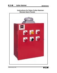
SECTIONAL DRAWING PAGE 23<br />
Figure 6<br />
STANDARD CONSTRUCTION
PAGE 24<br />
SECTIONAL DRAWINGS<br />
Figure 7<br />
REF.<br />
REF.<br />
DESCRIPTION<br />
NO.<br />
NO.<br />
DESCRIPTION<br />
1 IMPELLER C158 * BEARING HOUSING, INBOARD, OIL LUBE<br />
2 CASING, LOWER HALF D158 BEARING HOUSING, OUTBOARD, OIL LUBE<br />
2A * CAPSCREWS, CASING E158 * BEARING HOUSING, INBOARD, WATER-COOLED BEARING<br />
2B * PIN, CASING ALIGNMENT F158 BEARING HOUSING, OUTBOARD, WATER-COOLED BEARING<br />
2C * PIPE PLUG, CASING 158A * PIN, BEARING HOUSING ALIGNMENT<br />
3 CASING, UPPER HALF 158B * CAPSCREW, HOUSING<br />
4 SHAFT 158C LIPSEAL<br />
10 LANTERN RING 158D * PIPE PLUG, HOUSING<br />
A14 SHAFT SLEEVE A159 BEARING HOUSING COVER, GREASE LUBE<br />
B14 SHAFT SLEEVE, KEYED B159 BEARING HOUSING COVER, OIL LUBE<br />
16 WEARING RING, CASING C159 BEARING HOUSING COVER, WATER-COOLED BEARING<br />
17 WEARING RING, IMPELLER 159A O-RING, OIL LUBE COVER<br />
17A SETSCREW 159B O-RING, WATER-COOLED COVER<br />
19 PACKING GLAND, SPLIT 159C LIPSEAL<br />
20 WASHER, PACKING BOX 159D * CAPSCREW, HOUSING COVER<br />
A31 PACKING GLAND, SOLID 163 BEARING, INBOARD<br />
B31 GLAND, MECHANICAL SEAL 168 BEARING, OUTBOARD<br />
31A * GLAND STUD 212 PACKING<br />
31B * GLAND NUT 213 NUT, SHAFT SLEEVE<br />
102 KEY, IMPELLER 213A SETSCREW<br />
126 WATER SLINGER 272 KEY, COUPLING<br />
157 GASKET, CASING 345 SNAP RING<br />
A158 BEARING HOUSING, INBOARD, GREASE LUBE 452 O-RING, SHAFT SLEEVE<br />
B158 BEARING HOUSING, OUTBOARD, GREASE LUBE 456 SEAL, MECHANICAL<br />
* Not Shown