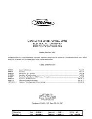
Relief Valve – Model TM 508-4KG-1 - Steven Brown & Associates
Relief Valve – Model TM 508-4KG-1 - Steven Brown & Associates
Relief Valve – Model TM 508-4KG-1 - Steven Brown & Associates

Create successful ePaper yourself
Turn your PDF publications into a flip-book with our unique Google optimized e-Paper software.
AUTOMATIC CONTROL VALVES<br />
50B-<strong>4KG</strong>-1<br />
Place this manual with personnel responsible<br />
for maintenance of this valve.<br />
INSTALLATION<br />
OPERATION<br />
MAINTENANCE<br />
®<br />
CLA-VAL • P.O. BOX 1325 • Newport Beach, CA 92659-0325 • (949) 722-4800<br />
CLA-VAL CANADA LTD. • 4687 Christie Drive • Beamsville, Ontario, Canada LOR 1B4 • (905) 563-4363
MODEL<br />
50B-<strong>4KG</strong>-1<br />
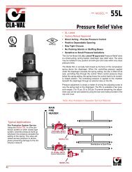
Fire Protection Pressure <strong>Relief</strong> <strong>Valve</strong><br />
UNDERWRITERS<br />
LISTED BY<br />
OF CANADA<br />
LABORATORIES<br />
• U.L. Listed/U.L.C. Listed<br />
• Factory Mutual Approved<br />
• Fast Opening to Maintain Steady Line Pressure<br />
• Accommodates Wide Range of Flow Rates<br />
• Closes Gradually for Surge-Free Operation<br />
• Adjustable Pressure Settings, Not Affected by<br />
Pressure At <strong>Valve</strong> Discharge<br />
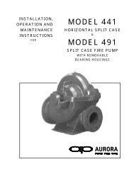
The Cla-Val <strong>Model</strong> 50B-<strong>4KG</strong>-1 Globe / 2050B-<strong>4KG</strong> Angle<br />
Pressure <strong>Relief</strong> <strong>Valve</strong> is designed specifically to automatically<br />
relieve excess pressure in fire protection pumping systems.<br />
Pilot controlled, it maintains constant system pressure<br />
at the pump discharge within very close limits as<br />
demands change.<br />
U.L. Listed...............Sizes 3" thru 8"<br />
F.M. Approved.........Sizes 3" thru 8"<br />
U.L.C. Listed............Sizes 2” thru 10”<br />
2050B-<strong>4KG</strong>1 (Angle)<br />
Typical Application<br />
Fire Pump<br />
<strong>Model</strong> 2050B-<strong>4KG</strong>-1<br />
Pressure <strong>Relief</strong> <strong>Valve</strong><br />
(Angle Pattern)<br />
Operation Sequence<br />
At pump start, Cla-Val <strong>Relief</strong> <strong>Valve</strong> modulates to relieve<br />
excess pump capacity, maintaining positive system pressure<br />
at the pump discharge.<br />
When fire demand slows or ceases, Cla-Val <strong>Model</strong><br />
50B-<strong>4KG</strong>-1 opens, diverting entire pump output to discharge,<br />
allowing fire pump to be stopped without causing<br />
surging in the lines.<br />
(Please note that if the <strong>Model</strong> 50B-<strong>4KG</strong>-1 is to be used on<br />
a continuous duty basis to maintain fire-system pressure,<br />
suitable back pressure must be provided on the valve to<br />
prevent cavitation damage. Consult the factory for details.)<br />
Check <strong>Valve</strong><br />
To Fire<br />
Protection System<br />
"Fluid Control at It's Best"
Specifications<br />
Dimensions<br />
Sizes<br />
End Details<br />
Pressure Ratings<br />
Materials<br />
Adjustment Range<br />
Specifications<br />
Sizes<br />
Globe: 2" - 12" flanged<br />
Angle: 2" - 12" flanged<br />
150 and 300 ANSI B16.42<br />
class - 175 psi Max.<br />
class - 300 psi Max<br />
Water, to 180°F Max.<br />
Main <strong>Valve</strong> Body & Cover<br />
Ductile Iron AS<strong>TM</strong> A-536<br />
Naval Bronze AS<strong>TM</strong> B61<br />
Other Material Available<br />
Standard Main <strong>Valve</strong> Trim:<br />
Bronze Seat, Teflon Coated<br />
Stainless Steel Stem, Delrin Sleeved<br />
Standard Pilot Control System:<br />
Cast Bronze with<br />
Stainless Steel trim<br />
Available in the following relief<br />
pressure ranges:<br />
20-200 psi (150 Class)<br />
100-300 psi (300 Class)<br />
Protective epoxy resin coating<br />
of wetted surfaces of main<br />
valve cast iron components<br />
(UL listed HNFX EX2855)<br />
Purchase Specifications<br />
The Fire Pump Pressure <strong>Relief</strong> <strong>Valve</strong> shall modulate to relieve excess<br />
pressure in a fire protection system. It shall maintain constant pressure<br />
in the system regardless of demand changes. It shall be pilot controlled<br />
and back pressure shall not affect its set point. It shall be actuated by<br />
line pressure through a pilot control system and open fast in order to<br />
maintain steady system pressure as system demand decreases. It shall<br />
close gradually to control surges and shall re-seat drip-tight within 5% of<br />
its pressure setting. The main valve shall be of the hydraulically-operated,<br />
pilot-controlled, diaphragm-type, globe or angle valve. It shall have<br />
a single, removable, teflon-coated seat, a delrin-sleeved stem guided at<br />
both ends, and a resilient disc with a rectangular cross section, being<br />
contained on 3 1/2 sides. No external packing glands shall be permitted<br />
and the diaphragm shall not be used as a seating surface. The pilot control<br />
shall be a direct-acting, adjustable, spring-loaded, diaphragm-type<br />
valve designed for modulating service to permit flow when controlling<br />
pressure exceeds spring setting. This valve shall be UL Listed and<br />
Factory Mutual approved. It shall be the MODEL 50B-<strong>4KG</strong>-1 (globe) or<br />
<strong>Model</strong> 2050B-<strong>4KG</strong>-1 (angle) Pressure <strong>Relief</strong> <strong>Valve</strong> as manufactured by<br />
Cla-Val Newport Beach, California.<br />
*Special Note:<br />
The <strong>Model</strong> 50B-<strong>4KG</strong>-1 Pressure <strong>Relief</strong> <strong>Valve</strong> is available with 300# ANSI<br />
inlet flange and 100# ANSI outlet flange. This valve is used on higher<br />
pressure systems where 300# flange connections are required, and<br />
allows for adapting of a discharge cone (generally supplied with 150#<br />
flange) to accommodate "atmospheric break" at relief valve discharge.<br />
This relief valve, with 300# X 150# flanges is available on special order,<br />
and is UNDERWRITERS LABORATORIES LISTED AND FACTORY<br />
MUTUAL APPROVED.<br />
Seawater Service Option<br />
Globe: 2" - 10" flanged<br />
Angle: 2" - 10" flanged<br />
Consult factory for materials and flange ratings.<br />
E-50B-<strong>4KG</strong>-1 (R-6/00)<br />
Optional<br />
CLA-VAL<br />
PO Box 1325 Newport Beach CA 92659-0325<br />
Phone: 949-722-4800 • Fax: 949-548-5441<br />
CLA-VAL CANADA, LTD.<br />
4687 Christie Drive<br />
Beamsville, Ontario<br />
Canada LOR 1B4<br />
Phone: 905-563-4963<br />
Fax: 905-563-4040<br />
©COPYRIGHT CLA-VAL 2000 Printed in USA<br />
Specifications subject to change without notice.<br />
CLA-VAL SA<br />
Chemin des Mesanges 1<br />
CH-1032 Romanel/<br />
Lausanne, Switzerland<br />
Phone: 41-21-643-15-55<br />
Fax: 41-21-643-15-50<br />
www.cla-val.com<br />
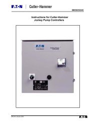
<strong>Model</strong> 50B-<strong>4KG</strong>-1 Globe<br />
A<br />
<strong>Valve</strong> Size (mm) 50 65 80 100 150 200<br />
Screwed Ends 238 279 318 -- -- --<br />
A 150 Flanged 238 279 305 381 <strong>508</strong> 645<br />
300 Flanged 254 295 337 397 533 670<br />
300 x 150 -- -- 327 389 522 670<br />
B 86 103 117 148 203 257 302 357<br />
C 305 311 318 330 363 414<br />
D 38 43 158 81 109 135<br />
Screwed Ends 121 140 159 -- -- --<br />
E 150 Flanged 121 140 152 191 254 324<br />
300 Flanged 127 423 162 200 267 337<br />
Screwed Ends 83 102 114 -- -- --<br />
F 150 Flanged 83 102 102 127 152 203<br />
300 Flanged 89 109 111 135 165 216<br />
G & H 152 170 197 200 216<br />
C<br />
D<br />
<strong>Model</strong> 2050B-<strong>4KG</strong>-1 Angle<br />
We recommend providing adequate space around valve for maintenance work.<br />
<strong>Valve</strong> Size (inches) 2" 2 1/2" 3" 4" 6" 8"<br />
Screwed Ends 9.38 11.00 12.50 -- -- --<br />
A 150 Flanged 9.38 11.00 12.00 15.00 20.00 25.38<br />
300 Flanged 10.00 11.62 13.25 15.62 21.00 26.38<br />
300 x 150 12.88 15.31 20.56 26.38<br />
C 12.00 12.25 12.50 13.00 14.31 16.31<br />
D 1.50 1.69 2.19 3.19 4.31 5.31<br />
Screwed Ends 4.75 5.50 6.25 -- -- --<br />
E 150 Flanged 4.75 5.50 6.00 7.50 10.00 12.75<br />
300 Flanged 5.00 5.88 6.38 7.88 10.50 13.25<br />
Screwed Ends 3.25 4.00 4.50 -- -- --<br />
F 150 Flanged 3.25 4.00 4.00 5.00 6.00 8.00<br />
300 Flanged 3.50 4.31 4.38 5.31 6.50 8.50<br />
G & H 6.00 6.69 7.75 7.88 8.50<br />
<strong>Valve</strong> Capacity<br />
<strong>Valve</strong> Sizes in Inches: 2" 2 3" 4" 6"<br />
NFPA 20 Maximum<br />
Recommended GPM 208 300 500 1000 2500<br />
H<br />
B<br />
G<br />
E<br />
9.75<br />
248<br />
8"<br />
C<br />
F<br />
10"<br />
--<br />
29.75<br />
31.72<br />
30.44<br />
18.00<br />
9.25<br />
--<br />
14.88<br />
15.56<br />
--<br />
8.62<br />
9.31<br />
13.25<br />
250<br />
--<br />
756<br />
806<br />
773<br />
457<br />
235<br />
--<br />
378<br />
395<br />
--<br />
219<br />
236<br />
337<br />
12"<br />
--<br />
34.00<br />
35.50<br />
34.75<br />
B 3.37 4.06 4.62 5.81 8.00 10.12 11.87 14.06<br />
Represented By:<br />
10"<br />
20.56<br />
10.75<br />
--<br />
17.00<br />
17.75<br />
--<br />
13.75<br />
14.50<br />
14.25<br />
300<br />
--<br />
864<br />
902<br />
883<br />
522<br />
273<br />
--<br />
432<br />
451<br />
--<br />
349<br />
368<br />
362<br />
12"<br />
5000 1100016000
®<br />
<br />
INSTALLATION / OPERATION / MAINTENANCE<br />
100-01<br />
MODEL<br />
Hytrol <strong>Valve</strong><br />
Description<br />
The CIa-VaI <strong>Model</strong> 100-01 Hytrol <strong>Valve</strong> is a main valve for<br />
CIa-VaI Automatic Control <strong>Valve</strong>s. It is a hydraulically operated,<br />
diaphragm-actuated, globe or angle pattern valve.<br />
This valve consists of three major components; body, diaphragm<br />
assembly, and cover. The diaphragm assembly is the only<br />
moving part. The diaphragm assembly uses a diaphragm of nylon<br />
fabric bonded with synthetic rubber. A synthetic rubber disc,<br />
contained on three and one half sides by a disc retainer and disc<br />
guide, forms a seal with the valve seat when pressure is applied<br />
above the diaphragm. The diaphragm assembly forms a sealed<br />
chamber in the upper portion of the valve, separating operating<br />
pressure from line pressure.<br />
Installation<br />
1. Before valve is installed, pipe lines should be flushed of all<br />
chips, scale and foreign matter.<br />
2. It is recommended that either gate or block valves be<br />
installed on both ends of the 100-01 Hytrol <strong>Valve</strong> to facilitate<br />
isoIating the valve for preventive maintenance and repairs.<br />
3. Place the valve in the line with flow through the valve in the<br />
direction indicated on the inlet nameplate. (See “Flow Direction”<br />
Section)<br />
4. Allow sufficient room around valve to make adjustments and<br />
for disassembly.<br />
5. CIa-VaI Co. 100-01 Hytrol <strong>Valve</strong>s operate with maximum<br />
efficiency when mounted in horizontal piping with the cover<br />
UP, however, other positions are acceptable. Due to size and<br />
weight of the cover and internal components of 8 inch and<br />
πlarger valves, installation with the cover UP is advisable. This<br />
makes internal parts readily accessible for periodic inspection.<br />
6. If a pilot control system is installed on the 100-01 Hytrol <strong>Valve</strong>,<br />
use care to prevent damage. If it is necessary to remove fittings<br />
or components, be sure they are kept clean and replaced<br />
exactly as they were.<br />
7. After the valve is installed and the system is first pressurized,<br />
vent air from the cover chamber and pilot system tubing by<br />
loosening fittings at all high points.<br />
Principles of Operation<br />
Three Way<br />
Pilot Control<br />
Three Way<br />
Pilot Control<br />
Restriction<br />
Modulating<br />
Control<br />
Tight Closing Operation<br />
When pressure from the valve inlet (or<br />
an equivalent independent operating<br />
pressure) is applied to the diaphragm<br />
chamber the valve closes drip-tight.<br />
Full Open Operation<br />
When pressure in diaphragm chamber<br />
is relieved to a zone of lower pressure<br />
(usually atmosphere) the line pressure<br />
(5 psi Min.) at the valve inlet opens the<br />
valve.<br />
Modulating Action<br />
<strong>Valve</strong> modulates when diaphragm pressure<br />
is held at an intermediate point<br />
between inlet and discharge pressure.<br />
With the use of a Cla-Val Co. "modulating<br />
control," which reacts to line pressure<br />
changes, the pressure above the<br />
diaphragm is varied, allowing the valve<br />
to throttle and compensate for the<br />
change.
Flow Direction<br />
The flow through the 100-01 Hytrol <strong>Valve</strong> can be in one of two<br />
directions. When flow is “up-and-over the seat,” it is in “normal”<br />
flow and the valve will fail in the open position. When flow is “overthe<br />
seat-and down,” it is in “reverse” flow and the valve will fail in<br />
the closed position. There are no permanant flow arrow markings.<br />
The valve must be installed according to nameplate data.<br />
Normal Flow<br />
Troubleshooting<br />
BRIDGEWALL INDlCATOR<br />
(cast into side of valve body)<br />
Reverse Flow<br />
The following troubleshooting information deals strictly with the<br />
<strong>Model</strong> 100-01 Hytrol <strong>Valve</strong>. This assumes that all other components<br />
of the pilot control system have been checked out and are<br />
in proper working condition. (See appropriate sections in<br />
Technical Manual for complete valve).<br />
Recommended Tools<br />
1. Three pressure gauges with ranges suitable to the installation<br />
to be put at Hytrol inlet, outlet and cover connections.<br />
2. Cla-Val <strong>Model</strong> X101 <strong>Valve</strong> Position Indicator. This provides<br />
visual indication of valve position without disassembly<br />
of valve.<br />
3. Other items are: suitable hand tools such as screwdrivers,<br />
wrenches, etc. soft jawed (brass or aluminum) vise,<br />
400 grit wet or dry sandpaper and water for cleaning.<br />
All trouble shooting is possible without removing the valve from the<br />
line or removing the cover. It is highly recommended to permanently<br />
install a <strong>Model</strong> X101 <strong>Valve</strong> Position Indicator and three gauges in<br />
unused Hytrol inlet, outlet and cover connections.<br />
SYMPTOM PROBABLE CAUSE REMEDY<br />
Fails to Close<br />
Closed cocks in control system, or in main line.<br />
Lack of cover chamber pressure.<br />
Open Cocks.<br />
Check upstream pressure, pilot system, strainer, tubing, cocks, or needle<br />
valves for obstruction.<br />
Fails to Open<br />
Diaphragm damaged. (See Diaphragm Check.)<br />
Diaphragm assembly inoperative.<br />
Corrosion or excessive scale build up on valve stem.<br />
(See Freedom of Movement Check)<br />
Mechanical obstruction. Object lodged in valve.<br />
(See Freedom of Movement Check)<br />
Worn disc. (See Tight Sealing Check)<br />
Badly scored seat. (See Tight Sealing Check)<br />
Closed upstream and/or downstream isolation<br />
valves in main line.<br />
Insufficient line pressure.<br />
Replace diaphragm.<br />
Clean and polish stem. Inspect and replace any damaged or badly eroded<br />
part.<br />
Remove obstruction.<br />
Replace disc.<br />
Replace seat.<br />
Open valves.<br />
Check upstream pressure. (Minimum 5 psi flowing line pressure differential.)<br />
Diaphragm assembly inoperative. Corrosion or excessive<br />
buildup on valve stem. (See Freedom of Movement Check)<br />
Diaphragm damaged. (For valves in "reverse flow" only)<br />
Clean and polish stem. Inspect and replace any<br />
damaged or badly eroded part.<br />
Replace diaphragm.<br />
After checking out probable causes and remedies, the following three checks can be used to diagnose the nature of the<br />
problem before maintenance is started. They must be done in the order shown.<br />
Three Checks<br />
The 100-01 Hytrol <strong>Valve</strong> has only one moving part (the diaphragm<br />
and disc assembly). So, there are only three major types of problems<br />
to be considered.<br />
First: <strong>Valve</strong> is stuck - that is, the diaphragm assembly is not free<br />
to move through a full stroke either from open to close or vice<br />
versa.<br />
Second: <strong>Valve</strong> is free to move and can’t close because of a worn<br />
out diaphragm.<br />
Thlrd: <strong>Valve</strong> leaks even though it is free to move and the<br />
diaphragm isn’t leaking.<br />
CAUTION:<br />
Care should be taken when doing the troubleroubleshooting<br />
checks on the 100-01 Hytrol <strong>Valve</strong>. These checks do require the<br />
valve to open fully. This will either allow a high flow rate through<br />
the valve, or the downstream pressure will quickly increase to<br />
the inlet pressure. In some cases, this can be very harmful.<br />
Where this is the case, and there are no block valves in the<br />
system to protect the downstream piping, it should be realized<br />
that the valve cannot be serviced under pressure. Steps<br />
should be taken to remedy this situation before proceeding any<br />
further.
Diaphragm Check (#1 )<br />
1. Shut off pressure to the Hytrol <strong>Valve</strong> by slowly closing upstream<br />
and downstream isolation valves. SEE CAUTION.<br />
2. Disconnect or close all pilot control lines to the valve cover and<br />
leave only one fitting in highest point of cover open to atmosphere.<br />
3.With the cover vented to atmosphere, slowly open upstream<br />
isolation valve to allow some pressure into the Hytrol <strong>Valve</strong> body.<br />
Observe the open cover tapping for signs of continuous flow. It is<br />
not necessary to fully open isolating valve. Volume in cover chamber<br />
capacity chart will be displaced as valve moves to open position.<br />
Allow sufficient time for diaphragm assembly to shift positions.<br />
If there is no continuous flow, you can be quite certain the<br />
diaphragm is sound and the diaphragm assembly is tight. If the<br />
fluid appears to flow continuously this is a good reason to believe<br />
the diaphragm is either damaged or it is loose on the stem. In<br />
either case, this is sufficient cause to remove the valve cover and<br />
investigate the leakage. (See “Maintenance” Section for procedure.)<br />
COVER CHAMBER CAPACITY<br />
(Liquid Volume displaced when valve opens)<br />
<strong>Valve</strong> size (inches) Displacement<br />
Gallons Liters<br />
1 1/4 .020 .07<br />
1 1/2 .020 .07<br />
2 .032 .12<br />
2 1/2 .043 .16<br />
3 .080 .30<br />
4 .169 .64<br />
6 .531 2.0<br />
8 1.26 4.8<br />
10 2.51 9.5<br />
12 4.00 15.1<br />
14 6.50 24.6<br />
16 9.57 36.2<br />
24 29.00 109.8<br />
Freedom of Movement Check (#2)<br />
4. Determining the Hytrol <strong>Valve</strong>’s freedom of movement can be<br />
done by one of two methods.<br />
5. For most valves it can be done after completing Diaphragm<br />
Check (Steps 1, 2, and 3). SEE CAUTION. At the end of step 3<br />
the valve should be fully open.<br />
6. If the valve has a Cla-Val Co. X101 Position Indicator, observe<br />
the indicator to see that the valve opens wide. Mark the point of<br />
maximum opening.<br />
7. Re-connect enough of the control system to permit the application<br />
of inlet pressure to the cover. Open pilot system cock so<br />
pressure flows from the inlet into the cover.<br />
8. While pressure is building up in the cover, the valve should<br />
close smoothly. There is a hesitation in every Hytrol <strong>Valve</strong> closure,<br />
which can be mistaken for a mechanical bind. The stem will<br />
appear to stop moving very briefly before going to the closed position.<br />
This slight pause is caused by the diaphragm flexing at a<br />
particular point in the valve’s travel and is not caused by a<br />
mechanical bind.<br />
9. When closed, a mark should be made on the X101 <strong>Valve</strong> position<br />
indicator corresponding to the “closed” position. The distance<br />
between the two marks should be approximately the stem travel<br />
shown in chart.<br />
STEM TRAVEL<br />
(Fully Open to Fully Closed)<br />
<strong>Valve</strong> Size (inches) Travel (inches)<br />
Inches MM Inches MM<br />
1 1/4 32 0.4 10<br />
1 1/2 40 0.4 10<br />
2 50 0.6 15<br />
2 1/2 65 0.7 18<br />
3 80 0.8 20<br />
4 100 1.1 28<br />
6 150 1.7 43<br />
8 200 2.3 58<br />
10 250 2.8 71<br />
12 300 3.4 86<br />
14 350 4.0 100<br />
16 400 4.5 114<br />
24 610 6.5 165<br />
0. If the stroke is different than that shown in stem travel chart this<br />
is a good reason to believe something is mechanically restricting<br />
the stroke of the valve at one end of its travel. If the flow does not<br />
stop through the valve when in the indicated “closed” position, the<br />
obstruction probably is between the disc and the seat. If the flow<br />
does stop, then the obstruction is more likely in the cover. In either<br />
case, the cover must be removed, and the obstruction located and<br />
removed. The stem should also be checked for scale build-up.<br />
(See “Maintenance, section for procedure.)<br />
11. For valves 6” and smaller, the Hytrol <strong>Valve</strong>’s freedom of movement<br />
check can also be done after all pressure is removed from<br />
the valve. SEE CAUTION. After closing inlet and outlet isolation<br />
valves and bleeding pressure from the valve, check that the cover<br />
chamber and the body are temporarily vented to atmosphere.<br />
Insert fabricated tool into threaded hole in top of valve stem, and<br />
lift the diaphragm assembly manually. Note any roughness. The<br />
diaphragm assembly should move smoothly throughout entire<br />
valve stroke. The tool is fabricated from rod that is threaded on<br />
one end to fit valve stem and has a “T” bar handle of some kind<br />
on the other end for easy gripping. (See chart in Step 4 of<br />
“Disassembly” Section.)<br />
12. Place marks on this diaphragm assembly lifting tool when the<br />
valve is closed and when manually positioned open. The distance<br />
between the two marks should be approximately the stem travel<br />
shown in stem travel chart. If the stroke is different than that<br />
shown, there is a good reason to believe something is mechanically<br />
restricting the stroke of the valve. The cover must be<br />
removed, and the obstruction located and removed. The stem<br />
should also be checked for scale build-up. (See “Maintenance”<br />
Section for procedure.)<br />
Tight Sealing Check (#3)<br />
13. Test for seat leakage after completing checks #1 & #2 (Steps<br />
1 to 12). SEE CAUTION. Close the isolation valve downstream of<br />
the Hytrol <strong>Valve</strong>. Apply inlet pressure to the cover of the valve, wait<br />
until it closes. Install a pressure gauge between the two closed<br />
valves using one of the two ports in the outlet side of the Hytrol.<br />
Watch the pressure gauge. If the pressure begins to climb, then<br />
either the downstream isolation valve is permitting pressure to<br />
creep back, or the Hytrol is allowing pressure to go through it.<br />
Usually the pressure at the Hytrol inlet will be higher than on the<br />
isolation valve discharge, so if the pressure goes up to the inlet<br />
pressure, you can be sure the Hytrol is leaking. Install another<br />
gauge downstream of isolating valve. If the pressure between the<br />
valves only goes up to the pressure on the isolation valve<br />
discharge, the Hytrol <strong>Valve</strong> is holding tight, and it was just the isolation<br />
valve leaking.
Maintenance<br />
Preventative Maintenance<br />
The Cla-Val Co. <strong>Model</strong> 100-01 Hytrol <strong>Valve</strong> requires no lubrication<br />
or packing and a minimum of maintenance. However, a periodic<br />
inspection schedule should be established to determine how the<br />
operating conditions of the system are affecting the valve. The<br />
effect of these actions must be determined by inspection.<br />
Disassembly<br />
Inspection or maintenance can be accomplished without removing<br />
the valve from the line. Repair kits with new diaphragm and<br />
disc are recommended to be on hand before work begins.<br />
WARNING: Maintenance personnel can be injured and equipment<br />
damaged if disassembly is attempted with pressure in the<br />
valve. SEE CAUTION.<br />
1. Close upstream and downstream isolation valves and independent<br />
operating pressure when used to shut off all pressure<br />
to the valve.<br />
2. Loosen tube fittings in the pilot system to remove pressure from<br />
valve body and cover chamber. After pressure has been released<br />
from the valve, use care to remove the controls and tubing. Note<br />
and sketch position of tubing and controls for re-assembly. The<br />
schematic in front of the Technical Manual can be used as a guide<br />
when reassembling pilot system.<br />
3. Remove cover nuts and remove cover. If the valve has been in<br />
service for any length of time, chances are the cover will have to<br />
be loosened by driving upward along the edge of the cover with a<br />
dull cold chisel.<br />
On 6” and smaller valves block and tackle or a power hoist can be<br />
used to lift valve cover by inserting proper size eye bolt in place<br />
of the center cover plug. on 8” and larger valves there are 4 holes<br />
(5/8” — 11 size) where jacking screws and/or eye bolts may be<br />
inserted for lifting purposes. Pull cover straight up to keep from<br />
damaging the integral seat bearing and stem.<br />
COVER CENTER PLUG SIZE<br />
<strong>Valve</strong> Size<br />
Thread Size (NPT)<br />
1 1/4"—1 1/2" 1/4"<br />
2"—3" 1/2"<br />
4"—6" 3/4"<br />
8"—10" 1"<br />
12" 1 1/4"<br />
14" 1 1/2"<br />
16" 2"<br />
24" 4 1/4"<br />
VALVE STEM THREAD SIZE<br />
<strong>Valve</strong> Size<br />
Thread Size (UNF Internal)<br />
1 1/4"—2 1/2" 10—32<br />
3"—4" 1/4—28<br />
6"—14" 3/8—24<br />
16" 1/2—20<br />
24" 3-12<br />
5. The next item to remove is the stem nut. Examine the stem<br />
threads above the nut for signs of mineral deposits or corrosion.<br />
If the threads are not clean, use a wire brush to remove as much<br />
of the residue as possible. Attach a good fitting wrench to the nut<br />
and give it a sharp “rap” rather than a steady pull. Usually<br />
several blows are sufficient to loosen the nut for further removal.<br />
On the smaller valves, the entire diaphragm assembly can be held<br />
by the stem in a vise equipped with soft brass jaws before<br />
removing the stem nut.<br />
The use of a pipe wrench or a vise without soft brass jaws scars<br />
the fine finish on the stem. No amount of careful dressing can<br />
restore the stem to its original condition. Damage to the finish of<br />
the stem can cause the stem to bind in the bearings and the valve<br />
will not open or close.<br />
6. After the stem nut has been removed, the diaphragm assembly<br />
breaks down into its component parts. Removal of the disc from<br />
the disc retainer can be a problem if the valve has been in service<br />
for a long time. Using two screwdrivers inserted along the outside<br />
edge of the disc usually will accomplish its removal. Care should<br />
be taken to preserve the spacer washers in water, particularly if<br />
no new ones are available for re-assembly.<br />
7. The only part left in the valve body is the seat which ordinarily<br />
does not require removal. Careful cleaning and polishing of inside<br />
and outside surfaces with 400 wet/dry sandpaper will usually<br />
restore the seat’s sharp edge. If, however, it is badly worn and<br />
replacement is necessary, it can be easily removed.<br />
Seats in valve sizes 1 1/4” through 6” are threaded into the valve<br />
body. They can be removed with accessory X109 Seat Removing<br />
Tool available from the factory. On 8” and larger valves, the seat<br />
is held in place by flat head machine screws. Use a tight-fitting,<br />
long shank screwdriver to prevent damage to seat screws. If upon<br />
removal of the screws the seat cannot be lifted out, it will be necessary<br />
to use a piece of angle or channel iron with a hole drilled<br />
in the center. Place it across the body so a long stud can be inserted<br />
through the center hole in the seat and the hole in the angle<br />
iron. By tightening the nut a uniform upward force is exerted on<br />
the seat for removal.<br />
NOTE: Do not lift up on the end of the angle iron as this may force<br />
the integral bearing out of alignment, causing the stem to bind.<br />
DO NOT<br />
LIFT<br />
NUT<br />
ANGLE OR CHANNEL IRON<br />
LONG STUD OR BOLT<br />
4. Remove the diaphragm and disc assembly from the valve body.<br />
With smaller valves this can be accomplished by hand by pulling<br />
straight up on the stem so as not to damage the seat bearing.<br />
On large valves, an eye bolt of proper size can be installed in the<br />
stem and the diaphragm assembly can be then lifted with a block<br />
and tackle or power hoist. Take care not to damage the stem or<br />
bearings. The valve won't work if these are damaged.<br />
VALVE SEAT<br />
VALVE BODY<br />
NUT OR BOLT HEAD
Lime Deposits<br />
One of the easiest ways to remove lime deposits from the valve<br />
stem or other metal parts is to dip them in a 5-percent muriatic<br />
acid solution just long enough for the deposit to dissolve. This<br />
will remove most of the common types of deposits. CAUTlON:<br />
USE EXTREME CARE WHEN HANDLING ACID. Rinse parts in<br />
water before handling. If the deposit is not removed by acid, then<br />
a fine grit (400) wet or dry sandpaper can be used with water.<br />
Inspection of Parts<br />
After the valve has been disassembled, each part should be<br />
examined carefully for signs of wear, corrosion, or any other<br />
abnormal condition. Usually, it is a good idea to replace the rubber<br />
parts (diaphragm and disc) unless they are free of signs of<br />
wear. These are available in a repair kit. Any other parts which<br />
appear doubtful should be replaced. WHEN ORDERlNG<br />
PARTS, BE SURE TO GIVE COMPLETE NAMEPLATE DATA,<br />
ITEM NUMBER AND DESCRlPTlON.<br />
NOTE: If a new disc isn’t available, the existing disc can be<br />
turned over, exposing the unused surface for contact with the<br />
seat. The disc should be replaced as soon as practical.<br />
Reassembly<br />
1. Reassembly is the reverse of the disassembly procedure. If a<br />
new disc has been installed, it may require a different number of<br />
spacer washers to obtain the right amount of “grip” on the disc.<br />
When the diaphragm assembly has been tightened to a point<br />
where the diaphragm cannot be twisted, the disc should be compressed<br />
very slightly by the disc guide. Excessive compression<br />
should be avoided. Use just enough spacer washers to hold the<br />
disc firmly without noticeable compression.<br />
2. MAKE SURE THE STEM NUT IS VERY TIGHT. Attach a good<br />
fitting wrench to the nut and give it a sharp “rap” rather than a<br />
steady pull. Usually several blows are sufficient to tighten the<br />
stem nut for final tightening. Failure to do so could allow the<br />
diaphragm to pull loose and tear when subjected to pressure.<br />
3. Carefully install the diaphragm assembly by lowering the stem<br />
through the seat bearing. Take care not to damage the stem or<br />
bearing. Line up the diaphragm holes with the stud or bolt holes<br />
on the body. on larger valves with studs, it may be necessary to<br />
hold the diaphragm assembly up part way while putting the<br />
diaphragm over the studs.<br />
4. Put spring in place and replace cover. Make sure diaphragm<br />
is Iying smooth under the cover.<br />
5. Tighten cover nuts firmly using a cross-over pattern until all<br />
nuts are tight.<br />
6. Test Hytrol <strong>Valve</strong> before re-installing pilot valve system.<br />
Test Procedure After <strong>Valve</strong> Assembly<br />
There are a few simple tests which can be made in the field to<br />
make sure the Hytrol <strong>Valve</strong> has been assembled properly. Do<br />
these before installing pilot system and returning valve to<br />
service. These are similar to the three troubleshooting tests.<br />
1. Check the diaphragm assembly for freedom of movement<br />
after all pressure is removed from the valve. SEE CAUTlON.<br />
Insert fabricated tool into threaded hole in top of valve stem, and<br />
lift the diaphragm assembly manually. Note any roughness,<br />
sticking or grabbing. The diaphragm assembly should move<br />
smoothly throughout entire valve stroke. The tool is fabricated<br />
from rod that is threaded on one end to fit valve stem (See chart<br />
in Step 4 of “Disassembly” section.) and has a “T” Bar handle of<br />
some kind on the other end for easy gripping.<br />
Place marks on this diaphragm assembly lifting tool when the<br />
valve is closed and when manually positioned open. The distance<br />
between the two marks should be approximately the stem<br />
travel shown in stem travel chart. (See “Freedom of Movement<br />
Check” section.) If the stroke is different than that shown, there<br />
is a good reason to believe something is mechanically restricting<br />
the stroke of the valve. The cover must be removed, the obstruction<br />
located and removed. (See “Maintenance” Section for<br />
procedure.)<br />
Due to the weight of the diaphragm assembly this procedure is<br />
not possible on valves 8” and larger. on these valves, the same<br />
determination can be made by carefully introducing a low<br />
pressure-less than five psi) into the valve body with the cover<br />
vented. SEE CAUTION. Looking in cover center hole see the<br />
diaphragm assembly lift easily without hesitation, and then<br />
settle back easily when the pressure is removed.<br />
2. To check the valve for drip-tight closure, a line should be<br />
connected from the inlet to the cover, and pressure applied at the<br />
inlet of the valve. If properly assembled, the valve should hold<br />
tight with as low as ten PSI at the inlet. See “Tight Sealing<br />
Check” section.)<br />
3. With the line connected from the inlet to the cover, apply full<br />
working pressure to the inlet. Check all around the cover for any<br />
leaks. Re-tighten cover nuts if necessary to stop leaks past the<br />
diaphragm.<br />
4. Remove pressure, then re-install the pilot system and tubing<br />
exactly as it was prior to removal. Bleed air from all high<br />
points.<br />
5. Follow steps under “Start-Up and Adjustment” Section in<br />
Technical Manual for returning complete valve back to service.
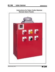
25<br />
2<br />
24<br />
Item<br />
Description<br />
PARTS LIST<br />
1. Pipe Plug<br />
2. Drive Screws (for nameplate)<br />
3. Hex Nut (6” and larger)<br />
4. Stud (6” and larger)<br />
INLET<br />
5<br />
8<br />
10<br />
26<br />
3<br />
4<br />
TOP VIEW<br />
1<br />
6<br />
16<br />
GLOBE PATTERN<br />
17<br />
9<br />
7<br />
OUTLET<br />
5. Cover Bearing<br />
6. Cover<br />
7. Stem Nut<br />
8. Diaphragm Washer<br />
9. Diaphragm<br />
10. Spacer Washers<br />
11. Disc Guide<br />
12. Disc Retainer<br />
13. Disc<br />
14. Stem<br />
15. Seat<br />
16. Body<br />
17. Spring<br />
22. Flat Head Screws (8” and larger)<br />
23. Seat O-Ring<br />
24. Hex head Bolt (1 1/4” thru 4”)<br />
25. Nameplate<br />
26. Upper Spring Washer (Epoxy coated valves only)<br />
27. Lower Spring Washer (Epoxy coated valves only)<br />
28. Cover Bearing Housing (16” only)<br />
29. Cover O-Ring (16’” only)<br />
30. Hex Bolt (16” only)<br />
31. Pipe Cap (16” only)<br />
11<br />
13<br />
27<br />
14<br />
22<br />
12<br />
15<br />
OUTLET<br />
23<br />
1 1/4" - 6" SEAT DETAIL<br />
31<br />
28<br />
INLET<br />
ANGLE PATTERN<br />
8" - 16" SEAT DETAIL<br />
;;;;;;; ;;;;;;;<br />
;;;;;;; ;;;;;;;<br />
;;;;;;; ;;;;;;;<br />
;;;;;;; ;;;;;;;<br />
;;;;;;; ;;;;;;; ;;;;;;; ;;;;;;;<br />
;;;;;;; ;;;;;;; ;;;;;;; ;;;;;;;<br />
;;;;;;; ;;;;;;;<br />
;;;;;;;<br />
;;;;;;;<br />
;;;;; ;;;;;<br />
;;;;;;; ;;;;;;;<br />
;;;;;;;<br />
;;;;;;;<br />
;;;;; ;;;;;<br />
;;;;;;; ;;;;;;;<br />
;;;;;;;<br />
;;;;;;;<br />
;;;;;;;<br />
;;;;;;;<br />
5<br />
30<br />
29<br />
16" COVER DETAIL<br />
CLA-VAL<br />
P.O. Box 1325 • Newport Beach, CA 92659-0325 • Phone: 949-722-4800 • Fax: 949-548-5441 • E-mail: claval@cla-val.com • Website cla-val.com<br />
©copyright Cla-Val 2000 Printed in USA Specification subject to change without notice.<br />
N-100-01 (R-5/00)
Roll Seal<br />
<strong>TM</strong><br />
®<br />
Parts List<br />
Regulator Spring Color Coding Chart<br />
Dwg#47117<br />
* THESE FIGURES ARE ONLY APPROXIMATE. FINAL ADJUS<strong>TM</strong>ENTS SHOULD BE MADE WITH A PRESSURE GAGE.<br />
WIRE SIZE SPRING NUMBER COLOR WIRE MATERIAL CATALOG NUMBER PSI RANGE *PSI PER TURN<br />
.080 DIA. C0492D BLUE S.S. CDB-7 0-7 .75<br />
CRL-5A 0-7 .75<br />
.080 DIA. 82575C -- S.S. CRD 1.9-6.5 .61<br />
CRD-10A 1.9-6.5 .49<br />
.116 DIA. 81594E -- S.S. CRD 2-30 3.0<br />
CRD-10A 2-30 2.4<br />
.120 DIA. V5654J GREEN CHR VAN CRL-5A 5-25 4.0<br />
CRD 10-40 4.0<br />
.162 DIA. 32447F NATURAL S.S. CDB-7 10-60 12.0<br />
CRL-5A 10-60 12.0<br />
CRL-13 10-60 12.0<br />
.162 DIA. V5695B YELLOW MUSIC WIRE CDB-7 20-80 14.5<br />
CRL-5A 20-80 14.5<br />
CRL-13 20-80 14.5<br />
.207 DIA. C11124B CAD PLT MUSIC WIRE CDB-7 50-150 29.5<br />
CRL-13 50-150 29.5<br />
CRL-5A 50-150 29.5<br />
.225 DIA. V6515A RED MUSIC WIRE CDB-7 65-180 44.0<br />
CRL-13 65-180 44.0<br />
CRL-5A 65-180 44.0<br />
.115 X .218 71884B RED CHR VAN CRL 0-75 8.5<br />
CRD 15-75 9.0<br />
CRD-10A 15-75 7.2<br />
.118 X .225 71885J GREEN CHR VAN CRL 20-200 28.0<br />
CRD 30-300 27.0<br />
CRD-10A 30-300 22.4<br />
.225 X .295 163021A CAD PLT CHR VAN CRL-5A 100-300 18.0<br />
CRL 100-300 18.0<br />
.440 X .219 48211H CAD PLT STEEL CRA-18 200-450 17.0<br />
CRD-22 200-450 17.0<br />
CRL-4A 100-450 17.0<br />
WIRE SIZE SPRING NUMBER COLOR WIRE MATERIAL CATALOG NUMBER PSI RANGE *PSI PER TURN<br />
.080 DIA. C0492D BLUE S.S. CRA 4.5-15 .82<br />
CRD-2 4.5-15 .82<br />
.375 DIA. 87719B EPOXY COATED CHROME CDS-5<br />
1 SPRING SILICON 5.40 1.0<br />
2 SPRING 30-80 2.0<br />
3 SPRING 70-120 3.0<br />
4 SPRING 110-120 4.0<br />
5 SPRING 150-200 5.0<br />
.072 DIA. V0597A -- 302SS CVC 1-17 .7<br />
THE FOLLOWING CONTROL & SPRING P/N#'S WERE REMOVED, 32656B, 31554K, 44591G, V65695B, & V5695B.<br />
ADDED CRL-13, CRL-5A, CRA, CRA-10A, CHANGED SPRING RANGES TO MATCH CURRENT CONTROLS.<br />
*This drawing is the property of CLA-VAL Co. and same and copies made therof, if any, shall be returned to it upon demand. Delivery and disclosure hereof are made<br />
soley upon condition that the same shall not be used, copied ore reproduced, nor shall the subject here of be disclosed in any manner to anyone for any purpose, except<br />
as herein authorized, without prior approval of CLA-VAL Co. Whether or not the equipment or information shown hereon is patented or otherwise protected, full title and<br />
copyrights if any, in and to this drawing and/or information delivered or submitted are fully reserved by CLA-VAL Co.<br />
CLA-VAL<br />
P.O. Box 1325 • Newport Beach, CA 92659-0325 • Phone: 949-722-4800 • Fax: 949-548-5441 • E-mail: claval@cla-val.com • Website cla-val.com<br />
©copyright Cla-Val 2000 Printed in USA Specification subject to change without notice.<br />
N-50B-<strong>4KG</strong>1 Dwg. 47117
®<br />
<br />
PARTS LIST<br />
81-01<br />
3/8" Check <strong>Valve</strong><br />
ITEM<br />
DESCRIPTION<br />
1. Cover Screw (8 Required)<br />
2. Cover<br />
*3. Spring<br />
4. Diaphragm Washer<br />
*5. Diaphragm<br />
*6. Disc Retainer Assembly<br />
7. Body Plug (3/8 NPT)<br />
8. Body (Screwed)<br />
*Recommended Spare Parts<br />
When ordering<br />
parts, please<br />
specify:<br />
• All nameplate data<br />
• Description<br />
• Part Number<br />
• Item Number<br />
• Material<br />
CLA-VAL<br />
P.O. Box 1325 • Newport Beach, CA 92659-0325 • Phone: 949-722-4800 • Fax: 949-548-5441 • E-mail: claval@cla-val.com • Website cla-val.com<br />
©copyright Cla-Val 2000 Printed in USA Specification subject to change without notice.<br />
PL-81-01 3/8" (R-6/00)
®<br />
<br />
PARTS LIST<br />
X44A<br />
Strainer and Orifice Assembly<br />
BRONZE BODY — S.S. ORIFICE<br />
3/8" x 3/8"<br />
X44A<br />
STOCK NO.<br />
71310-01<br />
-02<br />
-03<br />
-04<br />
-05<br />
-06<br />
* -07<br />
-08<br />
-09<br />
-10<br />
*Standard<br />
ORIFICE DIA.<br />
.031<br />
.046<br />
.062<br />
.078<br />
.093<br />
.109<br />
.125<br />
.140<br />
.156<br />
.187<br />
ORIFICE PLUG<br />
PART # (ITEM 5)<br />
94132-01<br />
-02<br />
-03<br />
-04<br />
-05<br />
-06<br />
-07<br />
-08<br />
-09<br />
-10<br />
When ordering parts, please specify:<br />
• All Nameplate Data<br />
• Item Number<br />
• Description<br />
• Recommended Spare Parts<br />
ITEM<br />
DESCRIPTION<br />
MATERIAL<br />
QTY.<br />
1<br />
Body<br />
Red Brs.<br />
1<br />
2<br />
Plug, Top<br />
Brass<br />
1<br />
3<br />
"O" Ring, Plug Top<br />
Syn. Rub.<br />
1<br />
4<br />
Screen<br />
Monel<br />
1<br />
5<br />
Orifice Plug<br />
Delrin<br />
1<br />
6<br />
Plug, Pipe<br />
Brass<br />
1<br />
7<br />
Strainer Plug<br />
S.S.<br />
1<br />
8<br />
"O" Ring, Strainer Plug<br />
Syn. Rub.<br />
1<br />
CLA-VAL<br />
P.O. Box 1325 • Newport Beach, CA 92659-0325 • Phone: 949-722-4800 • Fax: 949-548-5441 • E-mail: claval@cla-val.com • Website cla-val.com<br />
©copyright Cla-Val 2000 Printed in USA Specification subject to change without notice.<br />
P-X44A (R-6/00)
®<br />
<br />
INSTALLATION / OPERATION / MAINTENANCE<br />
MODEL<br />
Pressure Gauge<br />
Fire Protection Sprinkler Service<br />
• UL listed and Factory Mutual approved<br />
• Corrosion-resistant ABS case<br />
• Heat-resistant ploycarbonate push-in window<br />
• Patented PowerFlex <strong>TM</strong> movements with<br />
polyester segment<br />
• True Zero indication <strong>TM</strong> , a unique safety feature<br />
Description<br />
Ashcroft fire protection sprinkler gauges are Underwriters<br />
Laboratory listed and Factory Mutual approved for fire protection<br />
sprinkler service. The case material on Type 1 005P<br />
XUL gauges is ABS. The 0-300 psi pressure range is used<br />
on "wet" systems where water is available to the sprinkler<br />
heads. The 0-80 retard to 250 psi pressure range is used<br />
on dry systems where the lines are filled with air pressure<br />
until system activation.<br />
The patented PowerFlex movement with polyester segment<br />
is designed to provide unequalled shock and vibration<br />
resistance resulting in superior performance and<br />
extended gauge life.<br />
True Zero indication, a standard feature on<br />
these gauges, reduces the potential risk of<br />
installing a damaged gauge on your equipment.<br />
Gauge Options<br />
Customized dials<br />
Other UL listed ranges on application<br />
Specification<br />
Type no: 1005P, XUL<br />
Size: 3 1/2"<br />
Case:<br />
ABS (Acrylontrite Butadiene<br />
Styrene<br />
Ring:<br />
None<br />
Window: Polycarbonite. push-in<br />
Dial:<br />
Black figures on white<br />
Background<br />
Pointer:<br />
Black, aluminum<br />
Bourdon tube: "C" shaped bronze<br />
Movement: Patented PowerFlex<br />
Socket:<br />
Brass, soft soldered<br />
Restrictor: None<br />
Connection: 1/4 NPT lower<br />
Ranges: 0-300 psi (water)<br />
0-80 retard to 250 psi (air)<br />
UL 393 Listed, UL of Canada<br />
Listed and FM approved.<br />
Equivalent (single or dual scale)<br />
metric scales are available<br />
P/N 9028433C<br />
CLA-VAL<br />
P.O. Box 1325 • Newport Beach, CA 92659-0325 • Phone: 949-722-4800 • Fax: 949-548-5441 • E-mail: claval@cla-val.com • Website cla-val.com<br />
©copyright Cla-Val 2000 Printed in USA Specification subject to change without notice.<br />
N-PRESSURE GAUGE (R-10/99)
®<br />
<br />
Proper Identification<br />
For ordering repair kits, replacement parts, or for<br />
inquiries concerning valve operation it is important to<br />
properly identify Cla-Val products already in service.<br />
Include all nameplate data with your inquiry. Pertinent<br />
product data includes valve function, size, material,<br />
pressure rating, end details, type of pilot controls used<br />
and control adjustment ranges.<br />
Identification Plate<br />
For product identification, cast in body markings are<br />
supplemented by the identification plate illustrated on<br />
this page. The plate is mounted in the most practical<br />
position. It is extremely important that this identification<br />
plate is not painted over, removed, or in any<br />
other way rendered illegible.<br />
Specify when<br />
ordering<br />
• <strong>Model</strong> Number<br />
• Adjustment Range<br />
(As Applicable)<br />
• <strong>Valve</strong> Size<br />
• Optional Features<br />
• Pressure Class<br />
50B-<strong>4KG</strong>1/2050B-<strong>4KG</strong>1<br />
Product Identification<br />
How to Order<br />
How To Order<br />
There are many valves and controls<br />
manufactured by Cla-Val. that<br />
are not listed due to the sheer volume.<br />
For information not listed,<br />
please contact your local Cla-Val<br />
representative.<br />
Unless Otherwise<br />
Specified<br />
• X43 “Y” Strainer is<br />
included.<br />
• CK2 Isolation <strong>Valve</strong>s is<br />
included in price on 6" and<br />
larger valve sizes.<br />
Limited Warranty<br />
Automatic valves and controls as manufactured by Cla-Val are<br />
warranted for one year from date of shipment against manufacturing<br />
defects in material and workmanship which develop in the<br />
service for which they are designed, provided the products are<br />
installed and used in accordance with all applicable instructions<br />
and limitations issued by Cla-Val.<br />
We will repair or replace defective material, free of charge,<br />
which is returned to our factory, transportation charges prepaid,<br />
provided that, after inspection, the material is found to have<br />
been defective at time of shipment. This warranty is expressly<br />
conditioned on the purchaser’s giving Cla-Val immediate written<br />
notice upon discovery of the defect.<br />
Components used by Cla-Val but manufactured by others, are<br />
warranted only to the extent of that manufacturer’s guarantee.<br />
This warranty shall not apply if the product has been altered or<br />
repaired by others, and Cla-Val. shall make no allowance or<br />
credit for such repairs or alterations unless authorized in writing<br />
by Cla-Val.<br />
Terms Of Sale<br />
ACCEPTANCE OF ORDERS<br />
All orders are subject to acceptance by our main office at<br />
Newport Beach, California.<br />
CREDIT TERMS<br />
Credit terms are net thirty (30) days from date of invoice.<br />
PURCHASE ORDER FORMS<br />
Orders submitted on customer’s own purchase order forms will be<br />
accepted only with the express understanding that no statements,<br />
clauses, or conditions contained in said order form will be binding<br />
on the Seller if they in any way modify the Seller’s own terms and<br />
conditions of sales.<br />
PRODUCT CHANGES<br />
The right is reserved to make changes in pattern, design or materials<br />
when deemed necessary, without prior notice.<br />
PRICES<br />
All prices are F.O.B. Newport Beach, California, unless expressly<br />
stated otherwise on our acknowledgement of the order. Prices are<br />
subject to change without notice. The prices at which any order is<br />
accepted are subject to adjustment to the Seller’s price in effect at<br />
the time of shipment. Prices do not include sales, excise, municipal,<br />
state or any other Government taxes. Minimum order charge<br />
$75.00.<br />
RESPONSIBILITY<br />
We will not be responsible for delays resulting from strikes, accidents,<br />
negligence of carriers, or other causes beyond our control.<br />
Also, we will not be liable for any unauthorized product alterations<br />
or charges accruing there from.
Disclaimer Of Warranties And<br />
Limitations Of Liability<br />
The foregoing warranty is exclusive and in lieu of all other<br />
warranties and representations, whether expressed,<br />
implied, oral or written, including but not limited to any<br />
implied warranties or merchantability or fitness for a particular<br />
purpose. All such other warranties and representations<br />
are hereby cancelled.<br />
Cla-Val shall not be liable for any incidental or consequential<br />
loss, damage or expense arising directly or indirectly from<br />
the use of the product. Cla-Val shall not be liable for any<br />
damages or charges for labor or expense in making repairs<br />
or adjustments to the product. Cla-Val shall not be liable for<br />
any damages or charges sustained in the adaptation or use<br />
of its engineering data and services. No representative of<br />
Cla-Val may change any of the foregoing or assume any<br />
additional liability or responsibility in connection with the<br />
product. The liability of Cla-Val is limited to material replacements<br />
F.O.B. Newport Beach, California.<br />
Risk<br />
All goods are shipped at the risk of the purchaser after they have been<br />
delivered by us to the carrier. Claims for error, shortages, etc., must be<br />
made upon receipt of goods.<br />
EXPORT SHIPMENTS<br />
Export shipments are subject to an additional charge for export packing.<br />
RETURNED GOODS<br />
1. Customers must obtain written approval from Cla-Val prior to returning<br />
any material.<br />
2. Cla-Val reserves the right to refuse the return of any products.<br />
3. Products more than six (6) months old cannot be returned for credit.<br />
4. Specially produced, non-standard models cannot be returned for<br />
credit.<br />
5. Rubber goods cannot be returned for credit, unless as part of an<br />
unopened repair kit which is less than six months old.<br />
6. Goods authorized for return are subject to a 35% ($75 minimum)<br />
restocking charge and a service charge for inspection, reconditioning,<br />
replacement of rubber parts, retesting and repackaging as<br />
required.<br />
7. Authorized returned goods must be packaged and shipped prepaid to<br />
Cla-Val., 1701 Placentia Avenue, Costa Mesa, California 92627-<br />
4475.<br />
CLA-VAL<br />
P.O. Box 1325 • Newport Beach, CA 92659-0325 • Phone: 949-722-4800 • Fax: 949-548-5441 • E-mail: claval@cla-val.com • Website cla-val.com<br />
©copyright Cla-Val 2000 Printed in USA Specification subject to change without notice.<br />
N-50B-<strong>4KG</strong>1 P.I.D. (R-11/99)
INSTALLATION / OPERATION / MAINTENANCE<br />
®<br />
<br />
MODEL<br />
REPAIR KITS<br />
Complete Replacement Diaphragm Assemblies for 100-01 and 100-20 Hytrol Main <strong>Valve</strong>s<br />
For: Hytrol Main <strong>Valve</strong>s with Ductile Iron, Bronze Trim Materials—125/150 Pressure Class Only.<br />
Factory Assembled<br />
Includes: Stem, Disc Guide, Disc, Disc Retainer, Spacer Washers, Diaphragm, Diaphragm Washer<br />
and Stem Nut.<br />
<strong>Valve</strong> Size<br />
Diaphragm Assembly<br />
Stock Number<br />
100-01 100-20<br />
<strong>Valve</strong> Size<br />
Diaphragm Assembly<br />
Stock Number<br />
100-01 100-20<br />
3/8"<br />
1/2" - 3/4"<br />
1"<br />
1/4"-1 1/2"<br />
2"<br />
2 1/2"<br />
3"<br />
4"<br />
(Also 81-01 )<br />
(Also 81-01 )<br />
49097K<br />
C2518D<br />
C2520K<br />
C2522 F<br />
C2524B<br />
C2523D<br />
C2525J<br />
33273E<br />
N/A<br />
N/A<br />
N/A<br />
N/A<br />
N/A<br />
N/A<br />
C2524B<br />
C2525J<br />
6"<br />
8"<br />
10"<br />
12"<br />
14"<br />
16"<br />
20"<br />
24"<br />
40456G<br />
45276D<br />
81752J<br />
85533J<br />
89067D<br />
89068B<br />
N/A<br />
N/A<br />
33273E<br />
40456G<br />
45276D<br />
81752J<br />
N/A<br />
85533J<br />
89068B<br />
89068B<br />
Repair Kits for 100-01/100-20 Hytrol <strong>Valve</strong>s<br />
For: Hytrol Main <strong>Valve</strong>s—125/150 Pressure Class Only.<br />
Supplied Shrink Wrapped (4" and smaller) or Bagged (6" and larger)<br />
Includes: Diaphragm, Disc (or Disc Assembly) and spare Spacer Washers.<br />
<strong>Valve</strong><br />
Size<br />
3/8"<br />
1/2" - 3/4"<br />
1"<br />
1 1/4" - 1 1/2"<br />
2"<br />
2 1/2"<br />
3"<br />
4"<br />
6"<br />
8"<br />
10"<br />
12"<br />
14"<br />
16"<br />
20"<br />
24"<br />
Buna-N ® Standard Material<br />
(Also 81-01 )<br />
(Also 81-01 )<br />
Repair Kit<br />
Stock Number<br />
100-01 100-20<br />
9169801 K<br />
9169802H<br />
9169803F<br />
9169804D<br />
9169805A<br />
9169811J<br />
9169812G<br />
9169813E<br />
9169815K<br />
9817901 D<br />
9817902B<br />
9817903K<br />
9817904H<br />
9817905E<br />
N/A<br />
N/A<br />
N/A<br />
N/A<br />
N/A<br />
N/A<br />
N/A<br />
N/A<br />
9169805A<br />
9169812G<br />
9169813E<br />
9169815K<br />
9817901 D<br />
9817902B<br />
N/A<br />
9817903K<br />
9817905E<br />
9817905E<br />
<strong>Valve</strong><br />
Size<br />
3/8"<br />
1/2" - 3/4"<br />
1"<br />
1 1/4” - 1 1/2"<br />
2"<br />
2 1/2"<br />
3"<br />
4"<br />
6"<br />
8"<br />
Viton (For KB <strong>Valve</strong>s)<br />
Repair Kit<br />
Stock Number<br />
(Also 81-01 )<br />
(Also 81-01 )<br />
100-01 100-20<br />
9169806J<br />
9169807G<br />
9169808E<br />
9169809C<br />
9169810A<br />
9169817F<br />
9169818D<br />
9169819B<br />
9169820K<br />
N/A<br />
N/A<br />
N/A<br />
N/A<br />
N/A<br />
N/A<br />
N/A<br />
9169810A<br />
9169818D<br />
9169819B<br />
9169820K<br />
When ordering, please give complete nameplate data of the valve and/or control being repaired.<br />
MINIMUM ORDER CHARGE APPLIES.
Repair Kits for 100-02/100-21 Powertrol and 100-03/100-22 Powercheck Main <strong>Valve</strong>s<br />
For: Powertrol and Powercheck Main <strong>Valve</strong>s—125/150 Pressure Class Only<br />
Supplied Shrink Wrapped (4" and Smaller) or Bagged (6" and larger)<br />
Includes: Diaphragm, Disc (or Disc Assembly) and spare Spacer Washers.<br />
<strong>Valve</strong> Size Kit Stock Number <strong>Valve</strong> Size Kit Stock Number<br />
100-02<br />
100-02 &100-03 100-21 &100-22<br />
3/18"<br />
1/2" - 3/4"<br />
1"<br />
1 1/4" & 1 1/2"<br />
2"<br />
9169901H<br />
9169902F<br />
9169903D<br />
9169904B<br />
9169905J<br />
2 1/2"<br />
3"<br />
4"<br />
6"<br />
8"<br />
10"<br />
9169910J<br />
9169911G<br />
9169912E<br />
9169913C<br />
99116G<br />
N/A<br />
N/A<br />
9169905J<br />
9169911G<br />
9169912E<br />
9169913C<br />
99116G<br />
Larger Sizes: Consult Factory.<br />
Repair Kits for Pilot Control <strong>Valve</strong>s<br />
Supplied Shrink Wrapped<br />
Includes: Diaphragm, Disc (or Disc Assembly), O-Rings, Gaskets or spare Screws as appropriate.<br />
Pilot<br />
Control<br />
BUNA-N ® (Standard Material)<br />
Kit<br />
Stock<br />
Number<br />
CDB<br />
9170006C<br />
CDB-7<br />
9170017K<br />
CDH-2<br />
18225D<br />
CDHS-2<br />
44607A<br />
CDHS-2B<br />
9170004H<br />
CDHS-2F<br />
9170005E<br />
CDHS-3C-A2<br />
24657K<br />
CDHS-8A<br />
2666901A<br />
CDHS-18/CRD (no bucking spring) 9170003K<br />
CDS-4<br />
9170014G<br />
CDS-5<br />
14200A<br />
CDS-6<br />
20119301A<br />
CFM-2<br />
12223E<br />
Pilot<br />
Control<br />
CFM-7 & 7-A<br />
CRA (w/bucking spring)<br />
CRD (w/bucking spring)<br />
CRD-22<br />
CRL (55F)<br />
CRL-4A<br />
CRL-5<br />
CRL-5A (55G)<br />
CV<br />
X105L (O-ring)<br />
102B-1<br />
102C-2 & -3<br />
Kit<br />
Stock<br />
Number<br />
1263901K<br />
9170001D<br />
9170002B<br />
98923G<br />
9170007A<br />
43413E<br />
65755B<br />
20666E<br />
9170019F<br />
00951E<br />
1502201F<br />
1726201F<br />
Pilot<br />
Control<br />
CDB-KB<br />
CRA-KB<br />
CRD-KB (w/bucking spring)<br />
CRL-KB<br />
CDHS-2BKB<br />
CDHS-2FKB<br />
CDHS-18KB (no bucking spring)<br />
102C-KB<br />
Buna-N ®<br />
VITON (For KB Controls)<br />
CRD DISC RET. (SOLID)<br />
CRD DISC RET. (SPRING)<br />
Kit<br />
Stock<br />
Number<br />
9170012A<br />
9170018H<br />
9170008J<br />
9170013J<br />
9170010E<br />
9170011C<br />
9170009G<br />
1726202D<br />
C5256H<br />
C5255K<br />
Repair Assemblies (In Standard Materials Only)<br />
Control Description Stock Number<br />
CF1-C1<br />
CF1-Cl<br />
CFC2-C1<br />
CSM 11-A2-2<br />
CSM 11-A2-2<br />
33A 1"<br />
33A 2"<br />
Pilot Assembly Only<br />
Complete Float Control less Ball & Rod<br />
Disc, Distributor & Seals<br />
Mechanical Parts Assy.<br />
Pilot Assembly Only<br />
Complete Internal Assembly & Seal<br />
Complete Internal Assembly & Seal<br />
89541H<br />
89016A<br />
2674701E<br />
97544B<br />
18053K<br />
2036030B<br />
2040830J<br />
When ordering, please give complete nameplate data of the valve and/or control being repaired.<br />
MINIMUM ORDER CHARGE APPLIES.<br />
CLA-VAL<br />
P.O. Box 1325 • Newport Beach, CA 92659-0325 • Phone: 949-722-4800 • Fax: 949-548-5441 • E-mail: claval@cla-val.com • Website cla-val.com<br />
©copyright Cla-Val 2000 Printed in USA Specification subject to change without notice.<br />
N-RK (R-6/00)