Instruction Bulletin - Steven Brown & Associates
Instruction Bulletin - Steven Brown & Associates
Instruction Bulletin - Steven Brown & Associates

Create successful ePaper yourself
Turn your PDF publications into a flip-book with our unique Google optimized e-Paper software.
Fire Pump Controller For Electric Driven Fire Pumps(Produced after September 2002)Installation- Start Up - Service<strong>Instruction</strong><strong>Bulletin</strong>This instruction is a guide for personnel involved with Maintenance, Engineering and approval ofFire Pump equipment. It provides an understanding of the Joslyn Clark controller operation, toaid in installing start-up.Operation, Installation and test requirements are specified by the National Fire ProtectionAssociation, Publications NFPA 20, NFPA 70, NFPA 25 and Factory Mutual.Joslyn Clark Controls, LLC P.O. Box 945, Lancaster S.C. 29721-0945,Fax (803) 286-6624, Phone (803) 286-8491 or (800) 711-6627 WEB SITE www.joslynclark.com
<strong>Instruction</strong> <strong>Bulletin</strong>INDEXPAGEInstallation, Adjustments, Start-Up Operation ……..…. 2Electric Controller W/O Transfer SW …………………. 4Electric Controller W Transfer SW……………………. 6Electric Controller W Transfer SW 2 Utility………..….. 8Operator Interface .........................……………………11Operator Interface Operating <strong>Instruction</strong>s ………….…12Pressure Control & Display Operating <strong>Instruction</strong>s …. 15INSTALLATIONInstallation must meet requirements of the National Fire Protection Association publication"NFPA-20 and NFPA-70".SETTING IN PLACEThe controller must be located "within sight" of the motor, but so located that it will not be injuredby water escaping from the pump or connections.Mount the controller in a substantial manner on the wall, at a height which places currentcarrying parts not less than 12" above floor level (NFPA-20" requirements). Larger size floormounted enclosures include the necessary 12" floor clearance. A housekeeping floor pad isrecommended.WIRINGSpace available for entry of electrical conduits are detailed on controller submittal sheets anddimension outlines. All connections and service are made from the front. Rear access is notrequired.Incoming line power connects to top terminals of Isolating Switch IS, terminals L1-L2-L3. Foruse as service entrance equipment application, connect service ground conductor.Check controller nameplate to assure controller voltage is same as service voltage beinginstalled.Outgoing motor leads connect to bottom of Motor Contactor M, terminals T1, T2, T3 (Partwinding and Wye-Delta types connect to 1 M-2M contactors).Ground cabinet by wiring to ground lug provided near Isolating Switch.External control leads connect to control terminal board. Push Buttons: An optional remote"Start" push button can be added, wire to terminals 1-2.Note that remote "Stop" push buttons cannot be added. "NFPA-20" regulations permitthe use of no other "Stop" push button than the one mounted on the controller.Deluge Valve: When used, this connects to terminals 3-6, remove jumper 3-6. Valve contactsare closed when valve is closed.2
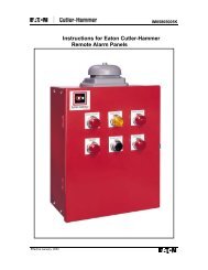
<strong>Instruction</strong> <strong>Bulletin</strong>Remote Alarms: "NFPA-20" requires that remote alarms be connected when the pump room isnot constantly attended. Alarms must be powered by a separate reliable supervised powersource. Make the following contact connections:• Connect "Pump Power Failure" to terminals 10-11 for contact "close" to alarm orterminals 11-12 for contact "open" to alarm.• Connect "Pump Running" alarm to terminals 13-14 for contact "close" to alarm orterminals 13A-14A for contact "open" to alarm.• Connect "Reverse Phase" alarm to terminals 76-77 for contacts "Close" to alarm.NOTE: Joslyn Clark <strong>Bulletin</strong> 10665 Alarm Panels are designed for use with all bulletins ofJoslyn Fire Pump Controllers.ELECTRICAL MAKE-READYRemove all packing and bindings which protect relays and contactors during shipment. Operateall contactors and relays by hand to assure free motion. Operate the "Start-Stop" push buttonsand the emergency start handle a few times to clean operating contacts from possible moistureor dust accumulated during shipping and installation work.PIPINGThreaded connection on the pressure sensor is accessible from front. Recommended pipe entryis through the bottom of wall-mounted controllers, and through the lower left side of floormountedtypes. Dimension details are shown on the outline diagram. When tightening piping,hold the square part of pressure sensor adaptor with wrench to avoid strain on transducer."NFPA-20" requires:a. Provision on the piping for relieving the pressure to test operation of the pressure switch (i.e.:drain valve).b. Pressure piping outside the controller may be not less than 1/2" nonferrous. Piping enteringcontroller may be 1/4".3
<strong>Instruction</strong> <strong>Bulletin</strong>ADJUSTMENTS1. Field setting of the Circuit Breaker is not needed. The Joslyn Clark Locked Rotor Protectoris factory set at 300% motor full load current, there are no adjustments.Circuit Breaker "instantaneous trip" is factory set to operate at no more than 2000% motor fullload current. This set-point is stamped on controller nameplate, handy when needed for futureverification.2. Adjust Pressure Control start and stop pressure settings to suit the exact installation (seeadjustment instruction page)3. The Running Period Timer, please refer to the Programming Mode for Recording PressureSwitch (RPS)4. On Reduced Voltage Controllers Accelerating Timer 1AT is factory set.10640 Autotransformer, Set 1AT - 3.0 Sec.10650 Primary Resistor, Set 1AT - 3 Sec.10670 Part Winding, Set 1AT - 1.5 Sec.10680 Y-Delta (Closed), Set 1AT - 2 Sec.10690 Y-Delta (Open), Set 1AT - 2.5 Sec.5. On Sequence Starting Controllers, the Sequential Timer, ST must be field set, asdetermined by the controller position in the "sequence." Set timer at:0 Seconds for Number 1 pump5 Seconds for Number 2 pump10 Seconds for Number 3 pump, etc., at 5 second intervals.OPERATING INFORMATION ELECTRIC FIRE PUMP CONTROLLER WITHOUTTRANSFER SWITCH.TRYOUT FOR CHECKING DIRECTION OF MOTOR ROTATION1. Power Supply switch (DISCONNECTING MEANS) should be open.2. Push “STOP” button while closing power supply switch. Release STOP button.3. Pump will start if water pressure is lower than the setting of the pressure switch.4. If pump starts, open power supply switch to “STOP”. (Check motor rotation).5. If pump does not start, press “START” button and stop by opening the power supply switch. (Checkmotor rotation).6. While doing the above, you will note the green light in the Display Unit indicates “Power Available &Voltage O.K.”, and the red light is off indicating that phases are in the correct sequence.NOTE: This controller is phase sequence sensitive. Correct phase sequence is indicated when thePhases Reversed light in the Display Panel is “OFF”. To correct, interchange any two incoming powerleads. To change motor rotation, interchange any two motor leads at the controller or at the motor.INITIAL START-UP1) Power supply switch should be open.2) Check pressure switch setting for START (low setting) and STOP (High setting). For programmingP.S. “settings” refer to Operating <strong>Instruction</strong>s provided with the controller.3) Push the “STOP” button while closing the power supply switch. Green light indicates “PowerAvailable”. Pump starts if pressure is low.4
<strong>Instruction</strong> <strong>Bulletin</strong>4) Pump continues to run for a period of 10 minutes (the minimum “setting” on the Running Period Timer– RPT), and longer if pressure is still low. The motor will then stop automatically. Motor may bestopped during the running period by pressing the “STOP” button, but will re-start when the button isreleased if pressure is still low. For programming RPT “setting” refer to Operating <strong>Instruction</strong>sprovided with the controller.5) For “Manual Stop” (RPT function is omitted) the pump will run until “stopped” by pressing the STOPbutton.6) To stop the motor while pressure is low, open the power supply switch.START FROM PUSHBUTTON1) Low water pressure starts the motor automatically, but the motor may be started manually at anywater pressure by pressing the “START” pushbutton on the controller cabinet or the remote “START”pushbutton, if used. A green light must be ON in the Display Unit indicating that power is availablebefore the motor can be started. (If light is not ON, follow initial start-up instructions).2) Following a pushbutton start, the motor will continue to run until stopped by the pushbutton on thecontroller. The Running Period Timer nor the pressure switch will stop the motor.START FROM MANUAL EMERGENCY START HANDLE1) For Manual Emergency operation, if motor does not start with the START button, raise the manualemergency Start handle quickly all the way and latch it in the raised position.2) To stop when the handle is latched in raised positionA) Open the power supply switchB) Unlatch the manual emergency handleC) Close the power supply switch.OPERATING SEQUENCE FOR DEVICES1) Under normal operating conditionsA) Power Supply Switch (Disconnecting Means) is closed.B) Green light in Display Unit is ON indicating 3Ph Power Available & Voltage(s) OK.C) Red light in Display Unit is OFF indicating that phase sequence is OK.D) Recording Pressure Switch will have been programmed for water pressure settings, RunningPeriod Timer function (if used) and Sequential Timer function (if used). (see Operating<strong>Instruction</strong>s supplied with the controller).E) The Power Monitor clock will have been programmed for the local time (see Operating<strong>Instruction</strong>s supplied with the controller).F) Relay CR1 is de-energized unless manual Pump Run was initiated by depression of the local orremote Start button. (CR1 energizes to start/run the pump)G) Relay CR2 is energized (drops out to start/run the pump).H) Relay CR3 will de-energize only when a phase failure is detected.I) Relay CR4 will energize only when Phases Reversed condition is detected.J) If the voltage drops below minimum voltage and then returns to above minimum (This canhappen during motor starting) the green Power Available light in the Display Unit will blink for 5seconds. This indicates that the power supply is marginal and may cause the fire pump not tostart.2) Relay CR1 is energized to start the motor when the “START” pushbutton is pressed or manualemergency handle is raised.3) Relay CR2 is de-energized to start the motor when:A) Pressure switch (PS) contact open due to low water pressure,B) Remote “Automatic Start” contact opens to start the motor (if used).4) Running Period Timer RPT (when used) starts timing on Automatic Start when CR2 drops out.Pressure switch operation will not stop the motor until (RPT) reaches its timed-out interval of 10minutes minimum. The red RPT light in the recorder unit shows that the timer is timing or timed outbut not reset. Timer resets when the motor stops.5) Sequence Timing function (when used) delays starting (5 seconds) so that on a two pump installationboth pumps do not start at once.5
<strong>Instruction</strong> <strong>Bulletin</strong>CIRCUIT BREAKER OPERATION1) The circuit breaker with a shunt trip and the locked rotor protection units are factory set and not fieldadjustable. The LRP provides a trip-time delay of not over 20 seconds. It is factory set to trip at300(+)%of the motor full load current.2) The circuit breakers instantaneous trip is factory set to operate at not more than 20 times motor fullload current.OPERATING INFORMATION ELECTRIC FIRE PUMP CONTROLLER WITHTRANSFER SWITCH FOR ON-SITE POWER GENERATION.TRYOUT FOR CHECKING DIRECTION OF MOTOR ROTATION1. Both Normal & Alternate Power Supply Switches (Disconnecting Means) should be open.2. Push “STOP” button while closing the Normal power supply switch. Release STOP button.3. Pump will start if water pressure is lower than the setting of the pressure switch.4. If pump starts, open Normal power supply switch to “STOP”. (Check motor rotation).5. If pump does not start, press “START” button and stop by opening the Normal power supply switch.(Check motor rotation).6. Check rotation from the Alternate power supply by opening the Normal power supply switch andclosing the Alternate power supply switch.7. While doing the above, you will note the green light in the Display Unit indicates “Power Available &Voltage O.K.”, and the red light is off indicating that phases are in the correct sequence. Also, notethe white light which indicates transfer switch on Normal Power supply and Yellow light to indicatetransfer switch is on Alternate power supply.NOTE: This controller is phase sequence sensitive. Correct phase sequence is indicated when thePhases Reversed light in the Display Panel is “OFF”. To correct, interchange any two incoming powerleads. To change motor rotation, interchange any two motor leads at the controller or at the motor.Also, the Automatic Transfer Switch is shipped for operation from the Normal power supply. If inAlternate power supply position, it will automatically transfer to Normal in step 2 above prior to pumpstarting.INITIAL START-UP1. Normal and Alternate Power supply switches should be open.2. Check pressure switch setting for START (low setting) and STOP (High setting). For programmingP.S. “settings” refer to Operating <strong>Instruction</strong>s provided with the controller.3. Push the “STOP” button while closing the Normal power supply switch. Green light indicates “PowerAvailable”. Pump starts if pressure is low.4. Pump continues to run for a period of 10 minutes (the minimum “setting” on the Running Period Timer– RPT), and longer if pressure is still low. The motor will then stop automatically. Motor may bestopped during the running period by pressing the “STOP” button, but will re-start when the button isreleased if pressure is still low. For programming RPT “setting” refer to Operating <strong>Instruction</strong>sprovided with the controller.5. For “Manual Stop” (RPT function is omitted) the pump will run until “stopped” by pressing the STOPbutton.6. To stop the motor while pressure is low, open the power supply switches.START FROM PUSHBUTTON1. Low water pressure starts the motor automatically, but the motor may be started manually at anywater pressure by pressing the “START” pushbutton on the controller cabinet or the remote “START”pushbutton, if used. A green light must be ON in the Display Unit indicating that power is availablebefore the motor can be started. (If light is not ON, follow initial start-up instructions).2. Following a pushbutton start, the motor will continue to run until stopped by the pushbutton on thecontroller. The Running Period Timer nor the pressure switch will stop the motor.3.6
<strong>Instruction</strong> <strong>Bulletin</strong>START FROM MANUAL EMERGENCY START HANDLE1. For Manual Emergency operation, if motor does not start with the START button, raise the manualemergency Start handle quickly all the way and latch it in the raised position.2. To stop when the handle is latched in raised positiona. Open the power supply switchesb. Unlatch the manual emergency handlec. Close the power supply switches.POWER SUPPLY TRANSFER FROM TEST SWITCH1) Close Alternate power supply switch2) Place manual test selector in Alternate position and hold, allowing time for engine to start. Transferswitch goes to Alternate supply. Selector switch will spring return to “Auto” position when released.Yellow light indicates transfer switch is on Alternate supply. The alarm sounds indicating it is inAlternate mode. If the Normal circuit breaker is closed the transfer switch will return to Normalautomatically in 30 minutes.NORMAL POWER SUPPLY FAILURE AUTOMATIC TRANSFER1) Close Alternate power supply switch.2) Open Normal power supply switch.3) After slight delay, control provides signal to start the engine4) Automatic transfer to Alternate supply occurs when Alternate supply reaches required voltage andfrequency. Yellow light indicates transfer to Alternate supply.5) Alarm may be silenced by pressing Silence alarm button.6) Pump will start on Alternate supply same as with Normal supply.7) To STOP the motor while pressure is low or manual emergency start handle is latched in raisedposition, open Alternate power supply switch.RE-TRANSFER TO NORMAL FROM ALTERNATE1) Close Normal power supply switch2) Re-transfer to Normal will occur automatically after 30 minutes’ time delay. Time delay may be bipassedby placing test selector switch momentarily (approximately 3 seconds) in Normal position orby opening alternate supply switch.OPERATING SEQUENCE FOR DEVICES1. Under normal operating conditionsa. Both Normal & Alternate Power Supply Switch (Disconnecting Means) are closed.b. Green light in Display Unit is ON indicating 3Ph Power Available & Voltage(s) OK.c. Red light in Display Unit is OFF indicating that phase sequence is OK.d. Recording Pressure Switch will have been programmed for water pressure settings, as haveRunning Period Timer function (if used) and Sequential Timer function (if used). (seeOperating <strong>Instruction</strong>s supplied with the controller).e. The Power Monitor clock will have been programmed for the local time (see Operating<strong>Instruction</strong>s supplied with the controller).f. Relay CR1 is de-energized unless manual Pump Run was initiated by depression of the localor remote Start button. (CR1 energizes to start/run the pump)g. Relay CR2 is energized (drops out to start/run the pump).h. Relay CR3 will de-energize only when a phase failure is detected.i. Relay CR4 will energize only when Phases Reversed condition is detected.j. If the voltage drops below minimum voltage and then returns to above minimum (This canhappen during motor starting) the green Power Available light in the Display Unit will blink for5 seconds. This indicates that the power supply is marginal and may cause the fire pump notto start.2. Relay CR1 is energized to start the motor when the “START” pushbutton is pressed or manualemergency handle is raised.3. Relay CR2 is de-energized to start the motor when:7
<strong>Instruction</strong> <strong>Bulletin</strong>a. Pressure switch (PS) contact open due to low water pressure,b. Remote “Automatic Start” contact opens to start the motor (if used).4. Running Period Timer RPT (when used) starts timing on Automatic Start when CR2 drops out.Pressure switch operation will not stop the motor until (RPT) reaches its timed-out interval of 10minutes minimum. The red RPT light in the recorder unit shows that the timer is timing or timed outbut not reset. Timer resets when the motor stops.5. Sequence Timing function (when used) delays starting (5 seconds) so that on a two pump installationboth pumps do not start at once.CIRCUIT BREAKER OPERATION1. The circuit breaker with a shunt trip and the locked rotor protection units are factory set and not fieldadjustable. The LRP provides a trip-time delay of not over 20 seconds. It is factory set to trip at300(+)%of the motor full load current.2. The circuit breakers instantaneous trip is factory set to operate at not more than 20 times motor fullload current.TRANSFER SWITCH OPERATION1) Normal supply voltage sensing is set to pick up at 95% and drop out at 90% of rated motor voltage2) Alternate supply sensing, set to pick up at 95% rated motor voltage and 95% of rated frequency.3) There is a 3 second time to over-ride momentary Normal source outages and delays all transferswitch and engine start signals.4) There is a 30 minute time delay on re-transfer to Normal supply from Alternate. This time delay isautomatically by-passed if the Alternate supply fails and Normal supply is available.5) There is a 5 minute unloaded running time delay for diesel engine cool-downOPERATING INFORMATION ELECTRIC FIRE PUMP CONTROLLER WITHTRANSFER SWITCH FOR 2 UTILITY POWER SOURCESTRYOUT FOR CHECKING DIRECTION OF MOTOR ROTATION1. Both Normal & Alternate Power Supply Switches (Disconnecting Means) should be open.2. Push “STOP” button while closing the Normal power supply switch. Release STOP button.3. Pump will start if water pressure is lower than the setting of the pressure switch.4. If pump starts, open Normal power supply switch to “STOP”. (Check motor rotation).5. If pump does not start, press “START” button and stop by opening the Normal power supply switch.(Check motor rotation).6. Check rotation from the Alternate power supply by opening the Normal power supply switch andclosing the Alternate power supply switch.7. While doing the above, you will note the green light in the Display Unit indicates “Power Available &Voltage O.K.”, and the red light is off indicating that phases are in the correct sequence. Also, notethe white light which indicates transfer switch on Normal Power supply and Yellow light to indicatetransfer switch is on Alternate power supply.NOTE: This controller is phase sequence sensitive. Correct phase sequence is indicated when thePhases Reversed light in the Display Panel is “OFF”. To correct, interchange any two incoming powerleads. To change motor rotation, interchange any two motor leads at the controller or at the motor.Also, the Automatic Transfer Switch is shipped for operation from the Normal power supply. If inAlternate power supply position, it will automatically transfer to Normal in step 2 above prior to pumpstarting.INITIAL START-UP1) Normal and Alternate Power supply switches should be open.2) Check pressure switch setting for START (low setting) and STOP (High setting). For programmingP.S. “settings” refer to Operating <strong>Instruction</strong>s provided with the controller.3) Push the “STOP” button while closing the Normal power supply switch. Green light indicates “PowerAvailable”. Pump starts if pressure is low.8
<strong>Instruction</strong> <strong>Bulletin</strong>4) Pump continues to run for a period of 10 minutes (the minimum “setting” on the Running Period Timer– RPT), and longer if pressure is still low. The motor will then stop automatically. Motor may bestopped during the running period by pressing the “STOP” button, but will re-start when the button isreleased if pressure is still low. For programming RPT “setting” refer to Operating <strong>Instruction</strong>sprovided with the controller.5) For “Manual Stop” (RPT function is omitted) the pump will run until “stopped” by pressing the STOPbutton.6) To stop the motor while pressure is low, open the power supply switches.START FROM PUSHBUTTON1) Low water pressure starts the motor automatically, but the motor may be started manually at anywater pressure by pressing the “START” pushbutton on the controller cabinet or the remote “START”pushbutton, if used. A green light must be ON in the Display Unit indicating that power is availablebefore the motor can be started. (If light is not ON, follow initial start-up instructions).2) Following a pushbutton start, the motor will continue to run until stopped by the pushbutton on thecontroller. The Running Period Timer nor the pressure switch will stop the motor.START FROM MANUAL EMERGENCY START HANDLE1) For Manual Emergency operation, if motor does not start with the START button, raise the manualemergency Start handle quickly all the way and latch it in the raised position.2) To stop when the handle is latched in raised positiona. Open the power supply switchesb. Unlatch the manual emergency handlec. Close the power supply switches.POWER SUPPLY TRANSFER FROM TEST SWITCH1) Close Alternate power supply switch2) Place manual test selector in Alternate position and hold, allowing time for engine to start. Transferswitch goes to Alternate supply. Selector switch will spring return to “Auto” position when released.Yellow light indicates transfer switch is on Alternate supply. The alarm sounds indicating it is inAlternate mode. If the Normal circuit breaker is closed the transfer switch will return to Normalautomatically in 30 minutes.NORMAL POWER SUPPLY FAILURE AUTOMATIC TRANSFER1) Close Alternate power supply switch.2) Open Normal power supply switch.3) After slight delay, Automatic transfer to Alternate supply occurs when Alternate supply reachesrequired voltage and frequency. Yellow light indicates transfer to Alternate supply.4) Alarm may be silenced by pressing Silence alarm button.5) Pump will start on Alternate supply same as with Normal supply.6) To STOP the motor while pressure is low or manual emergency start handle is latched in raisedposition, open Alternate power supply switch.RE-TRANSFER TO NORMAL FROM ALTERNATE1) Close Normal power supply switch2) Re-transfer to Normal will occur automatically after 30 minutes’ time delay. Time delay may be bipassedby placing test selector switch momentarily (approximately 3 seconds) in Normal position orby opening alternate supply switch.OPERATING SEQUENCE FOR DEVICES1) Under normal operating conditionsA) Both Normal & Alternate Power Supply Switch (Disconnecting Means) are closed.B) Green light in Display Unit is ON indicating 3Ph Power Available & Voltage(s) OK.C) Red light in Display Unit is OFF indicating that phase sequence is OK.9
<strong>Instruction</strong> <strong>Bulletin</strong>D) Recording Pressure Switch will have been programmed for water pressure settings, as haveRunning Period Timer function (if used) and Sequential Timer function (if used). (see Operating<strong>Instruction</strong>s supplied with the controller).E) The Power Monitor clock will have been programmed for the local time (see Operating<strong>Instruction</strong>s supplied with the controller).F) Relay CR1 is de-energized unless manual Pump Run was initiated by depression of the local orremote Start button. (CR1 energizes to start/run the pump)G) Relay CR2 is energized (drops out to start/run the pump).H) Relay CR3 will de-energize only when a phase failure is detected.I) Relay CR4 will energize only when Phases Reversed condition is detected.J) If the voltage drops below minimum voltage and then returns to above minimum (This canhappen during motor starting) the green Power Available light in the Display Unit will blink for 5seconds. This indicates that the power supply is marginal and may cause the fire pump not tostart.2) Relay CR1 is energized to start the motor when the “START” pushbutton is pressed or manualemergency handle is raised.3) Relay CR2 is de-energized to start the motor when:4) Pressure switch (PS) contact open due to low water pressure,5) Remote “Automatic Start” contact opens to start the motor (if used).6) Running Period Timer RPT (when used) starts timing on Automatic Start when CR2 drops out.Pressure switch operation will not stop the motor until (RPT) reaches its timed-out interval of 10minutes minimum. The red RPT light in the recorder unit shows that the timer is timing or timed outbut not reset. Timer resets when the motor stops.7) Sequence Timing function (when used) delays starting (5 seconds) so that on a two pump installationboth pumps do not start at once.CIRCUIT BREAKER OPERATION1) The circuit breaker with a shunt trip and the locked rotor protection units are factory set and not fieldadjustable. The LRP provides a trip-time delay of not over 20 seconds. It is factory set to trip at300(+)%of the motor full load current.2) The circuit breakers instantaneous trip is factory set to operate at not more than 20 times motor fullload current.TRANSFER SWITCH OPERATION1) Normal supply voltage sensing is set to pick up at 95% and drop out at 90% of rated motor voltage2) Alternate supply sensing, set to pick up at 95% rated motor voltage and 95% of rated frequency.3) There is a 3 second time to over-ride momentary Normal source outages and delays all transferswitch and engine start signals.4) There is a 30 minute time delay on re-transfer to Normal supply from Alternate. This time delay isautomatically by-passed if the Alternate supply fails and Normal supply is available.10
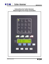
<strong>Instruction</strong> <strong>Bulletin</strong>Operator Interface1 Display Area – Normal display will show the three phase current and voltage. Will alsoshow any alarm conditions, event history, and settings.2 Scroll Up Key – Scrolls forward through the menus.3 Scroll Down Key – Scrolls reverse through the menus.4 Power Available Indicator – Green indicator lights when incoming power is at anacceptable level on all three phases.5 Phases Reversed Indicator – Red indicator lights when incoming power is not in properrotation.6 Impending L.R. Trip – Red indicator will flash when the motor current equals or exceedslocked rotor levels.7 Enter Key – Use to accept new programmable parameter (time, date, etc.).8 Down Arrow Key – Lower programmable parameters.9 Up Arrow Key – Raises programmable parameters.10 Change Setup Indicator – Red indicator lights when the unit is in the program mode.11 Setup Indicator – Red indicator lights when in the setup view mode. Use the scroll keysto view the settings (time, date).12 Setpoint Indicator – Red indicator lights when in the setpoint view mode. Use the scrollkeys to view the operating paramagnets (current trip point, voltage setting, etc.).13 Event History Indicator – Red indicator lights when in the event history mode. Use thescroll keys to view the events.14 Normal Mode Indicator – Red indicator lights when in the normal operating mode.Operator Interface Operating <strong>Instruction</strong>s11
<strong>Instruction</strong> <strong>Bulletin</strong>Normal Mode OperationWith the system operating in the normal mode, the Normal Mode Indicator (item 14) and thePower Available Indicator (item 4) will be lit. The display will be indicating the current andvoltages of all three phases.Motor CurrentPhase Phase PhaseA B CSupply VoltagePhases Phases PhasesA-B B-C C-ATypical DisplayOther information capable of being displayed in the Normal Mode using the Scroll Up (item 2) orthe Scroll Down (item 3) key is:• Three phase motor current only with average current• Three phase voltage only with average voltage• Current and Voltage imbalance• Number of motor starts• Number of circuit breaker trips• Any pending faultsEvent History ModeIn the Event History Mode, the user may view the last seventy events. Each event issequentially numbered and date stamped. Enter the Event History by pressing the Mode Key(item 15) until the Event History (item 13) indicator lights. The display will read as shown below.Event History Mode Start DisplayUsing the Down Arrow (item 8) or Up Arrow (item 9), the display will scroll through the mostrecent event recorded (event 1) and the time of the last pump start. Use the Scroll Down (item3) key to view the event history items in an ascending sequence (event 2, 3, 4…) or the ScrollUp (item 2) key to view the history items in a descending sequence (event 70, 69, 68…). Usethe Up Arrow (item 9) key to return to the start display.Typical Event DisplaySetpoint ModeIn the Setpoint Mode, the operating parameters of the system can be viewed. Press the ModeKey (item 15) until the Setpoint (item 12) indicator lights and the display reads as shown.12
<strong>Instruction</strong> <strong>Bulletin</strong>Setpoint Mode DisplayThe parameters include• Current Limit – the ampere level where the locked rotor protection system starts to operate.• Current Multiplier – shall equal the input ratio of the current transformers. If no currenttransformers are used, the value will be 1.• Nominal Voltage – set to the motor voltage.• Voltage Multiplier – shall equal the ratio of the input potential transformers on mediumvoltage controller. On low voltage controllers, the value will be 1.Operating <strong>Instruction</strong>sIn the normal operating mode, the Normal Mode indicator (item 14) will be lit. If all three phasesof the supply voltage are acceptable, the Power Available Indicator (item 4) will be lit. Thedisplay will show the motor current and supply voltage similar to the illustration below.Motor CurrentPhase Phase PhaseA B CSupply VoltagePhases Phases PhasesA-B B-C C-ATypical DisplayThe above display is expandable for further information on motor current and supply voltageand to view any faults in the supply system. To view the expanded displays:1. Press the Scroll Down Key (item 3). The expanded motor current display will appear. Itshows the three phase motor current plus the average current.2. Press the Scroll Down Key (item 3) again. The expanded supply voltage display willappear. It shows the three phase supply current plus the average voltage.3. Press the Scroll Down Key (item 3) again. The current and voltage unbalance screen willappear.4. Press the Scroll Down Key (item 3) again. The screen that appears tracks the number oftimes the fire pump motor started and the number of times the locked rotor protectoroperated (tripped) since a clear history request.5. Press the Scroll Down Key (item 3) again. The fault menu will appear along with any faultspresent at the time.13
<strong>Instruction</strong> <strong>Bulletin</strong>Fault messages that can appear are:• LV Low Voltage on one or more phases• OC Motor Over Current, impending trip• PR Phases Reversed• VUB Voltage Un-Balance greater than 18%6. Press the Scroll Down Key (item 3) once more to return to the normal operating modedisplay.Testing the SystemThe Operator Interface Panel can be used to test the power monitor system and the fire pumpcontroller for Phase Loss, Phases Reverse and Locked Rotor Test. To test these functions:1. Push and hold the Down Arrow (item 8) and Up Arrows (item 9) Keys. The display will showthe following:2. To test the Lock Rotor function, press the Mode Key (item 15) while holding the Down Arrow(item 8) and the Up Arrow (item 9) Keys. The Impending Locked Rotor Indicator (item 6) willstart flashing and the display will show:3. After 12 seconds, the system will energize the shunt trip mechanism in the fire pump circuitbreaker causing the circuit breaker to trip, shutting off the fire pump controller.4. Pull the Circuit Breaker (Disconnecting Means) handle on the fire pump controller to the fulldown position to reset the circuit breaker.5. Press and hold the Stop pushbutton on the fire pump controller, move the Circuit Breaker(Disconnecting Means) handle to the full up position to restore power to the fire pumpcontroller.6. Release the Stop pushbutton.7. To test the Phases Reversed function, press and hold the Down Arrow (item 8) and the UpArrow (item 9) Keys to get the test menu, then press the Scroll Up Key (item 2). ThePhases Reversed Indicator (item 5) will light and the display will show:8. Any remote alarm systems connected to the fire pump controller should indicate a phasesreversed condition.9. Release the keys, the display will return to the normal.10. To test the Phase Failure Function, press and hold the Down Arrow (item 8) and the UpArrow (item 9) Keys to get the test menu, then press the Scroll Down Key (item 3). ThePower Available Indicator (item 4) will extinguish and the display will show:11. Any remote alarm systems connected to the fire pump controller should indicate a phase orpower failure condition.12. Release the keys, the display will return to the normal.14
<strong>Instruction</strong> <strong>Bulletin</strong>Pressure Control Display & Logging Operating <strong>Instruction</strong>sRecording Pressure Switch (RPS)Initial Set Up1. Complete piping installation to pressure transducer.2. Open the cover to gain access to the Recording Pressure Gauge.Recording Pressure Switch (RPS) Power Up1 Remove the security cover from the MODE selector switch at the lower left of the recording pressuregauge; verify the switch is in the RUN position.2 Turn on the fire pump controller power. Close the disconnecting means of the fire pump controller.3 The recorder power up sequence is as follows:SequenceApprox. Time(seconds)Description Display Pen Movement1 0 system test starts none2 3 firmware revision level PX.XXstarts to home (0)position3 6 ½ display blanks at home position4 7 system test completecurrent system starts to currentpressure system pressureChart Change Mode1 Depress the Scroll Key once. The display should indicate CC.15
<strong>Instruction</strong> <strong>Bulletin</strong>2 Depress the Down Arrow Key . The display should be flashing CC and the chart pen will start tomove away from the chart hub.3 Pull open the chart lock on the chart hub.4 Place a chart onto the chart hub and seat the chart under the three chart guides.5 Push to close the chart lock on the hub.6 Press the Down Arrow Key , the display and chart pen should show the current system pressure.Set Point AdjustmentsNote: the minimal differential setting between the set points is 1 pressure unit. The recording pressureswitch will automatically maintain this differential if an attempt to overlap the set points is made.1 Remove the anti-tamper cover from the MODE switch.2 Place the MODE switch in the PROG/CAL TEST position. The display will show SP (for Set Point).3 Press the Down Arrow Key once; the display will show CIn (for Cut in or start pressure setting).4 Press the Scroll Key once; the display will show the current start pressure set point.5 Use the Up Arrow Key or the Down Arrow Key to adjust the start pressure set point.Pushing the keys once will change the setting one pressure unit. To change a setting rapidly, pushand hold the appropriate key, the setting will start changing slowly at first; the speed will increase thelonger the key is held.6 Once the Cut in is set, press the Scroll Key once to accept the new setting. The display will nowshow COut (for Cut Out or stop pressure setting).7 Press the Scroll Key once; the display will show the current stop pressure set point.8 Use the Up Arrow Key or the Down Arrow Key to adjust the stop pressure set point.Pushing the keys once will change the setting one pressure unit. To change a setting rapidly, pushand hold the appropriate key, the setting will start changing slowly at first, the speed will increase thelonger the key is held.9 When the Cut Out is set, press the Scroll Key once to accept the new setting. The display willshow the CIn indication again.10 Place the MODE switch back into the RUN position. The display will indicate the current systempressure. Install the anti-tamper cover.11 To verify the current CIn and COut settings, momentarily press the Down Arrow Key . Thedisplay will first show CIn followed by the present setting, then COut followed by the present settingand return back to the system pressure display.Programming Mode –This procedure is used to set the operating parameters of the recording pressure switch. The settingsshown in the following chart are the standard factory settings and in some cases will be modified to suitthe customer’s requirements.1 Remove the anti-tamper cover from the MODE switch.2 Place the MODE switch in the PROG/CAL TEST position. The display will show SP (for SetPoint).3 Press and hold the Scroll Key until the display shows Prog (for Program mode).4 Press the Down Arrow Key to enter the programming mode; the display will show InP1 (forInPut 1). The following chart describes the programmable parameters and their default settings.Use the Scroll Key to move to the next menu item, use the Up Arrow Key or the Down16
<strong>Instruction</strong> <strong>Bulletin</strong>Arrow Keyto change the setting. The new setting will automatically be saved when theScroll Key is pressed to move to the next menu item.5 After the programming is complete, place the MODE switch into the RUN position, install the antitampercover.Parameter Code Description Setting or Range Default Setting Factory SettingPressureInP10 = 0-5 volt devicetransducer input1 1InPut #11 = 1-5 volt devicerangeIcorInput CorrectionEUUEngineered UnitsUpperEULEngineered UnitsLowerChUPChart UPper LimitChLOChart LOwer LimitInP2InPut #2ChSPChart SPeedrPtrunning PeriodtimerSStSequential StartTimerSttSystem test timerCalibrates the inputsignal (if needed)Sets the maximumdisplayed value tothat of the pressuretransducerSets the minimumdisplayed value tothat of the pressuretransducerSets the upperrange of the chart,usually the sameas the EUU valueSets the lowerrange of the chart,usually the sameas the EUL valueManual Stopswitch inputSets the chartspeed, match withtype of chart usedEnables the timerfunction andselects the timerangeSelects startdelay time periodSelects thenumber of daysbetweenautomaticsystem tests-999 to +999 0 As required0 to +9999 3000 to +9999 0 0-9999 to +9999 300-9999 to +9999 0 00 = 0-5 volt device1 = 1-5 volt deviceOFF = no rotation8Hr = 8 hour12Hr = 12 Hour24Hr = 24 Hour48Hr = 48 Hour7dAy = 7 DaysOFF = Manual Stop10 = 10 Minutes15 = 15 Minutes20 = 20 Minutes30 = 30 Minutes0 to 30 Seconds 00 07dAyOff0 to 30 days 0 0300 (psi) or asneeded bycustomerrequirements300 (psi) or asneeded bycustomerrequirements7dAy10 Minutes0 or as neededby customerrequirements17
<strong>Instruction</strong> <strong>Bulletin</strong>Test Mode –The test mode checks and confirms the functionality of the recording pressure switch.1 Remove the anti-tamper cover from the MODE switch.2 Place the MODE switch in the PROG/CAL TEST position. The display will show SP (for SetPoint).3 Press and hold the Scroll Key until the display shows Prog (for Program mode).4 Press the Scroll Key once more, the display will read tESt.5 Press the Down Arrow Key to start the test. The following sequence shall occur:a. All segments in the display area and all status LED’s will illuminate for 5 seconds.b. The display area and all status LED’s will turn off for 5 seconds.c. The display will show SCrL, press the Scroll Key .d. The display will show UAro, press the Up Arrow Key .e. The display will show dAro, press the Down Arrow Key .f. The display will show diSP, the display and keypad test function is complete.6 Press the Scroll Key , the display will read Chrt for the Chart test.7 Press the Down Arrow Key to start the test. The following sequence shall occur:a. The chart will start rotating at about ¾ revolutions per minute. The pen will start swingingtowards the full scale of the chart. When the pen reaches the full scale position, it willreverse and start swinging towards the center of the chart. When the pen reaches theminimum scale of the chart, it will again reverse direction. The sequence will continueuntil the test is ended.b. Press any key to terminate the chart test, the display will show Chrt.c. Press the Up Arrow Key , the display will show tEst.8 Place the MODE switch in the RUN position.9 Install the anti-tamper cover.Sequence of Operation1 Upon the system pressure dropping below the start setting, the red PRESSURE LOW indicatorwill light.2 If the sequential start timer is set greater than zero seconds, the time cycle will start at this time,the red START DELAY indicator will light. If during this time delay the pressure restores abovethe stop setting, the recording pressure gauge will reset to the standby mode, and the greenPRESSURE NORMAL indicator will light.3 After the sequential start time delay, if set, or when the pressure drops to below the start setting ifthe timer is not set, the output relay of the recording pressure switch will change states. When therelay operates, it’s control contact opens, which causes the fire pump controller to start the firepump motor. The red RPT ON indicator will light if the running period timer is set, the time rangesavailable are 10, 15, 20 and 30 minutes. If the timer is set to off, the red indicator will not light.4 The recording pressure switch will keep the fire pump operating until the system pressure risesabove the stop setting and the running period time elapses. The red RPT ON indicator will turnoff at the end of the time period. When the pressure is above the stop setting, the greenPRESSURE NORMAL indicator will illuminate.5 If the running period timer is set to off, the pump motor will continue to operate until the systempressure is above the stop setting as indicated by the green PRESSURE NORMAL indicator andthe STOP pushbutton is depressed. If the STOP pushbutton is depressed before the systempressure increases to above the stop setting, the fire pump will continue to operate.18
Joslyn Clark Electric Fire Pump ControllersType D10600Renewal PartsUsed On DescriptionPart NumberPMR Fire Pump Power Monitor, 20-90 Amp, 200-480 Volt A10-460313-1PMR Fire Pump Power Monitor, 90-180 Amp, 200-480 Volt A10-460313-2PMR Fire Pump Power Monitor, 2-9 Amp, 200-480 Volt A10-460313-3PMR Fire Pump Power Monitor, 20-90 Amp, 575 Volt A10-460313-4PMR Fire Pump Power Monitor, 90-180 Amp, 575 Volt A10-460313-5PMR Fire Pump Power Monitor, 2-9 Amp, 575 Volt A10-460313-6Fire Pump Power Monitor, 2-9 Amp, 120-240 VoltA10-460313-7PMR Communication Module A10-460314Display User Interface Panel A10-460315RPS Recording Pressure Gauge (Standard) A10-460316-1RPS Recording Pressure GaugeW/Test Relay A10-460316-2RPS Recording Pressure Gauge W/Watchdog Alarm Relay A10-460316-3RPS Recording Pressure Gauge W/Test & Watchdog Alarm Relay A10-460316-4RPS Recorder Chart 300 PSI 213884RPS Recorder Chart 600 PSI 213818RPS 5 Pack Pens 60500402Pressure Transducer, 300 PSI, 1-5 VDC OutputA10-461070-1Pressure Transducer, 600 PSI, 1-5 VDC OutputA10-461070-2TR2 100 VA Control Transformer 200 Volt Pri/120 Volt Sec. TR67-96TR2 100 VA Control Transformer 230/460 Volt Pri/120 Volt Sec TR67-97TR2 100 VA Control Transformer 575 Volt Pri/120 Volt Sec. TR67-98TR1 50 VA Control Transformer 200 Volt Pri/120 Volt Sec. TR97-93TR1 50 VA Control Transformer 230/460 Volt Pri/120 Volt Sec TR67-94TR1 50 VA Control Transformer 575 Volt Pri/120 Volt Sec. TR67-95CR1,CR2 RELAYSA22-457280-3CR1,CR2, Relay Socket A22-457281AT Accelerating Timer (Reduced Voltage Type Only) A22-458328-51PB Start Push Button + N5B10VN N5CPNVG2PB Stop Push Button + N5B01VN & N5B11VN N5CPNRGF1 Mod. K Fuses FNM 1 amp A22-421644-9LS Emergency Run Limit Switch A10-308267M,1M,2M CONTACTORS WITHOUT AUXILARY CONTACTSAdd VOLTAGE SUFFIXES (-1=208V, -2=240V, -3=380V, -4=480V, -5=575)SIZE 2SIZE 3SIZE 4SIZE 5SIZE 6A77-358452A-A77-358453A-A77-358454A-A77-357400A-A77-302335A-Joslyn Clark Page 1 10/8/2002
M,1M,2M COILSSIZE 2 200V-208VSIZE 2 220V-240VSIZE 2 380V, 50HzSIZE 2 380V, 60HzSIZE 2 415V, 50HzSIZE 2 460V-480VSIZE 2 575SIZE 3 200V-208VSIZE 3 220V-240VSIZE 3 380V, 50HzSIZE 3 380V, 60HzSIZE 3 415V, 50HzSIZE 3 460V-480VSIZE 3 575SIZE 4 200V-208VSIZE 4 220V-240VSIZE 4 380V, 50HzSIZE 4 380V, 60HzSIZE 4 415V, 50HzSIZE 4 460V-480VSIZE 4 575SIZE 5 200V-208VSIZE 5 220V-240VSIZE 5 380V, 50HzSIZE 5 380V, 60HzSIZE 5 415V, 50HzSIZE 5 460V-480VSIZE 5 575SIZE 6 200V-208VSIZE 6 220V-240VSIZE 6 380V, 50HzSIZE 6 380V, 60HzSIZE 6 415V, 50HzSIZE 6 460V-480VSIZE 6 575TB159-10TB159-2TB159-11TB159-6TB159-3TB159-3TB159-4TB162-14TB162-8TB162-15TB162-15TB162-9TB162-9TB162-10TB162-16TB162-2TB162-17TB162-17TB162-3TB162-3TB162-4L7L2L12L13L3L3L4TB163-5TB163-2TB163-6TB163-6TB163-3TB163-3TB163-4M,1M,2M AUXILIARY CONTACTS FOR MAIN CONTACTORSSIZE 2,3, & 4 TM N.O. AuxKTM10SIZE 2,3, & 4 TM N.C. AuxKTM11SIZE 5 N.O.Aux 5M-063SIZE 5 N.C.Aux 5M-064SIZE 5 N.O. & N.C.Aux 5M-065SIZE 6 N.O. AuxKTM35-10SIZE 6 N.C. AuxKTM35-11Surge Arrestor 208VSurge Arrestor 220V-415VVSurge Arrestor 460V & UPA19-453641-1A19-453641-2A19-453641-3Joslyn Clark Page 2 10/8/2002