GE Zenith Controls - Steven Brown & Associates
GE Zenith Controls - Steven Brown & Associates
GE Zenith Controls - Steven Brown & Associates

Create successful ePaper yourself
Turn your PDF publications into a flip-book with our unique Google optimized e-Paper software.
e<br />
<strong>GE</strong><br />
<strong>Zenith</strong> <strong>Controls</strong><br />
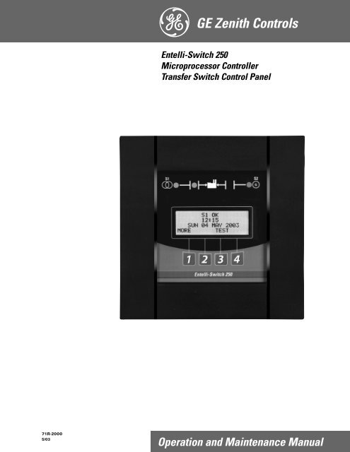
Entelli-Switch 250<br />
Microprocessor Controller<br />
Transfer Switch Control Panel<br />
71R-2000<br />
5/03<br />
Operation and Maintenance Manual
Authorized Service<br />
For <strong>GE</strong> parts and service, call: (773) 299-6600<br />
Table of Contents<br />
Page<br />
Introduction . . . . . . . . . . . . . . . . . . . . . . . . . . . . . .12<br />
Safety . . . . . . . . . . . . . . . . . . . . . . . . . . . . . . . . . . .13<br />
Equipment Inspection and Storage . . . . . . . .13<br />
Final Equipment Inspection . . . . . . . . . . . . . .13<br />
Installation . . . . . . . . . . . . . . . . . . . . . . . . . . . . . . .14<br />
Engine Start Control Connections . . . . . . . . .14<br />
Initial Energization . . . . . . . . . . . . . . . . . . .14-5<br />
Control Connections . . . . . . . . . . . . . . . . . . . .6<br />
Entelli-Switch 250 Microprocessor Controller . . . .17<br />
Overview . . . . . . . . . . . . . . . . . . . . . . . . . . . . .17<br />
LCD & Keypad . . . . . . . . . . . . . . . . . . . . . . . .18<br />
User Setting for Voltage & Frequency . . . . . .19<br />
Accessory Group Packages. . . . . . . . . . . . . . . .10<br />
Accessory Definitions . . . . . . . . . . . . . . . . .11-14<br />
How to Set the System Clock . . . . . . . . . . . . .14<br />
CDT One Event Timer Exerciser . . . . . . . . . .15<br />
CDP Clock Exerciser . . . . . . . . . . . . . . . . . . . .16<br />
User Setup - CFG Menu . . . . . . . . . . . . . . . . .17<br />
User Setup - SET Menu . . . . . . . . . . . . . . . . . .18<br />
User Setup - System Info . . . . . . . . . . . . . . . . .19<br />
Page<br />
Testing . . . . . . . . . . . . . . . . . . . . . . . . . . . . . . . . .120<br />
Introduction . . . . . . . . . . . . . . . . . . . . . . . . .120<br />
Test Options . . . . . . . . . . . . . . . . . . . . . . . . . .20<br />
Standard Transition . . . . . . . . . . . . . . . . . . . .121<br />
Delayed Transition . . . . . . . . . . . . . . . . . . . . .21<br />
Closed Transition . . . . . . . . . . . . . . . . . . . . . .22<br />
Emergency Service Procedure<br />
for Extended Parallel Time . . . . . . . . . . . . . . .23<br />
Sequence of Operation . . . . . . . . . . . . . . . . . . . . .24<br />
Standard Transition . . . . . . . . . . . . . . . . . . . .124<br />
Delayed Transition . . . . . . . . . . . . . . . . . . . . .24<br />
Closed Transition . . . . . . . . . . . . . . . . . . . . . .25<br />
Relay/Transformer (R/T Box) . . . . . . . . . . . . . . .26<br />
Standard . . . . . . . . . . . . . . . . . . . . . . . . . . . .126<br />
Delay . . . . . . . . . . . . . . . . . . . . . . . . . . . . . . .127<br />
Schematics . . . . . . . . . . . . . . . . . . . . . . . . . . .128<br />
Troubleshooting & Diagnostics . . . . . . . . . . . . . . .29<br />
Maintenance and Testing . . . . . . . . . . . . . . . . . . . .30<br />
Inspection and Cleaning . . . . . . . . . . . . . . . . .30<br />
Servicing . . . . . . . . . . . . . . . . . . . . . . . . . . . .130<br />
Testing . . . . . . . . . . . . . . . . . . . . . . . . . . . . . .130<br />
Introduction<br />
<strong>GE</strong> <strong>Zenith</strong> Transfer Switches are used to provide a continuous source of power for lighting and other critical loads by<br />
automatically transferring from source 1 power to source 2 power in the event that source 1 voltage falls below preset limits.<br />
Voltage sensing and system control is performed via a state-of-the-art microcontroller located on the cabinet door.<br />
It is designed to give highly accurate control of the transfer switch system.<br />
All <strong>GE</strong> <strong>Zenith</strong> transfer switches are designed for use on emergency or standby systems, and are rated for total system or<br />
motor loads. Transfer switches are UL Listed under Standard 1008 and CSA Certified under Standard C22.2 No. 178 and<br />
IEC Listed under Standard 947.<br />
NOTES:<br />
A protective device such as a molded case circuit breaker or fused<br />
disconnect switch MUST be installed on both sources of incoming<br />
power for circuit protection and as a disconnection device.<br />
All references made within this manual about the term “S1” or<br />
“Source 1” relate to a Normal Power Source. All references made<br />
about the term “S2” or “Source 2” relate to an Emergency<br />
or Alternative Power Source.
Safety / Installation<br />
DAN<strong>GE</strong>R<br />
HAZARDOUS VOLTA<strong>GE</strong><br />
(Can Cause Severe Injury or Death)<br />
Turn OFF all power before installation, adjustment, or removal of transfer switch or any of its components.<br />
The safe operation of your switch is <strong>GE</strong> <strong>Zenith</strong>’s focus.<br />
The proper storage, installation, operation and maintenance<br />
will help increase the life of the switch.<br />
Equipment Inspection<br />
and Storage<br />
Once you have received the transfer switch, inspect<br />
it for any damage. This includes damage to the<br />
enclosure, power panel, control panel and wiring<br />
harness. If any damage is found or suspected, file a claim<br />
as soon as possible with the carrier and notify the nearest<br />
<strong>GE</strong> <strong>Zenith</strong> representative.<br />
Before installation, if it is necessary, store the transfer<br />
switch in a clean dry place, protected from dirt and<br />
water. Provide ample air circulation and heat, if necessary,<br />
to prevent condensation.<br />
-30°C to<br />
+75°C<br />
(-22°F to<br />
+167°F)<br />
CAUTION<br />
Due to hazardous voltage and current, <strong>GE</strong> <strong>Zenith</strong> recommends<br />
that a <strong>GE</strong> <strong>Zenith</strong> Certified technician or a<br />
qualified electrician must perform the<br />
installation and maintenance of the switch.<br />
Operating<br />
Storage Temperature<br />
Temperature (Ambient): Humidity<br />
Table 1<br />
40-400 AMP<br />
(molded shell)<br />
-20°C to +65°C<br />
(-4°F to +149°F)<br />
40-4000 AMP<br />
(all other frame<br />
and panel types)<br />
-20°C to +60°C<br />
(-4°F to +140°F)<br />
5% to 95%<br />
(non-condensing)<br />
Final Equipment Inspection<br />
Prior to energizing the transfer switch:<br />
1. Remove any debris incurred, with a vacuum, due<br />
to shipment or installation.<br />
2. Verify that all cabled connections are<br />
correct and that phase rotation of both sources<br />
match.<br />
3. Check engine start connections.<br />
4. Verify the correct connection of all<br />
control wires.<br />
5. Check settings of all timers and adjust<br />
as necessary.<br />
6. Adjust any optional accessories as required.<br />
7. Check the lug torque values of the power<br />
connections.<br />
NOTE: Lug torque values are specified<br />
in the power panel manual.<br />
8. Make sure that all covers and barriers are<br />
installed and properly fastened.<br />
NOTE:<br />
Power panels ship from <strong>GE</strong> <strong>Zenith</strong><br />
in Source 1 Position.<br />
WARNING<br />
Do not use a blower since debris may<br />
become lodged in the electrical and<br />
mechanical components and cause damage.<br />
Each <strong>GE</strong> <strong>Zenith</strong> transfer switch is factory wired and<br />
tested. A complete information package is furnished<br />
with each switch which includes:<br />
a. Sequence of operation.<br />
b. Description and operation of<br />
all accessories supplied.<br />
c. Power panel connection diagram<br />
and schematic.<br />
d. Description and identification of<br />
all customer field connections.<br />
Installation of <strong>GE</strong> <strong>Zenith</strong> transfer switches includes:<br />
a. Mounting the transfer switch cabinet.<br />
b. Connection of Source 1, Source 2,<br />
and Load cables or bus bars.<br />
c. Connection of external control<br />
circuits as required.<br />
■ <strong>GE</strong> <strong>Zenith</strong> <strong>Controls</strong><br />
Entelli-Switch 250 Operation and Maintenance Manual (71R-2000)<br />
3 ■
Installation (cont’d)<br />
DAN<strong>GE</strong>R<br />
HAZARDOUS VOLTA<strong>GE</strong><br />
(Can Cause Severe Injury or Death)<br />
Turn OFF all power before installation, adjustment, or removal of transfer switch or any of its components.<br />
E<br />
4<br />
5<br />
6<br />
Figure 1<br />
1<br />
P Relay<br />
2<br />
(Engine Start)<br />
3<br />
Contact rating is<br />
10 Ampere at 120VAC<br />
or 28VDC Gold plated<br />
Engine Start<br />
Control Connections<br />
The engine-start terminals are clearly identified by a<br />
label on the microcontroller backplate. In the case of<br />
manual transfer switches, or in other applications not<br />
requiring the microprocessor, clearly marked terminal<br />
blocks are provided in the upper left corner of the control<br />
panel for the engine start control wires.<br />
Figure 2 shows location of engine start connections<br />
for Bypass Isolation Transfer Switch. Figure 5 (pg.6)<br />
shows location of engine start connections for<br />
Automatic Transfer Switch.<br />
Terminals for field connections to the A3 Source 2<br />
auxiliary contacts and the A4 Source 1 auxiliary contacts<br />
are also provided. These terminals are clearly marked<br />
and appear on the side of the power panel. On 400<br />
amp metal frame units these terminals appear on<br />
the bracket above the operator handle.<br />
Initial Energization<br />
Before proceeding, refer to the information package<br />
supplied with the ATS and read and understand the<br />
information on all accessories provided.<br />
1. Unlock the enclosure.<br />
2. Open the enclosure.<br />
3. Verify the correct system voltage.<br />
NOTE: The equipment rating nameplate on<br />
the transfer switch lists the voltage.<br />
See Figure 3.<br />
4. Close Source 1 circuit. breaker.<br />
NOTE:The controller will illuminate Source 1<br />
Available LED if proper voltage<br />
is sensed.<br />
5. Verify the phase to phase voltages at Source 1<br />
line terminals.<br />
6. Close Source 2 circuit breaker.<br />
7. Start the generator’s engine.<br />
NOTE: The controller will illuminate Source 2<br />
Available LED when preset voltage<br />
and frequency levels are reached.<br />
8. Verify the phase to phase voltages at Source 1<br />
line terminals.<br />
9. Verify that the phase rotation of Source 1<br />
is the same as the phase rotation of<br />
Source 2.<br />
10. Shut down the generator’s engine.<br />
11. Place the starting control in the Automatic position.<br />
12. Complete the visual inspection of the transfer switch.<br />
13. Close the enclosure.<br />
14. Lock the enclosure.<br />
g<br />
<strong>GE</strong> <strong>Zenith</strong> <strong>Controls</strong><br />
SERIAL NUMBER:<br />
RATING: VOLTS -<br />
AMPS -<br />
SYSTEM VOLTS:<br />
MODEL NUMBER:<br />
HZ -<br />
PHASE -<br />
Figure 3<br />
CAUTIONS<br />
Figure 2 (Typical)<br />
Certain accessories, per specific<br />
schematics, can inhibit automatic transfer.<br />
Engine Gen-Set could start when<br />
engine control wires are attached.<br />
■ 4<br />
Entelli-Switch 250 Operation and Maintenance Manual (71R-2000)<br />
<strong>GE</strong> <strong>Zenith</strong> <strong>Controls</strong> ■
Installation (cont’d)<br />
Initial Energization (cont’d)<br />
After all options and accessories are checked and<br />
verified, follow these steps to set up the ATS. Refer to<br />
Entelli-Switch 250 display Figure 4. The annunciation<br />
LEDs illuminate to indicate (1) source availability,<br />
(2) ATS position, and (3) Entelli-Switch 250 control<br />
function (timing).<br />
1. Unlock the enclosure.<br />
2. Open the enclosure.<br />
3. Place the Disconnect Switch in the Inhibit.<br />
NOTE: This step is only performed if the<br />
“DS” Option was purchased.<br />
4. Close the external (up-stream) Source 1<br />
circuit breaker.<br />
NOTES: Source 1 Available and Source 1<br />
Position LED’s will illuminate.<br />
Figure 4 –<br />
S1 OK<br />
21:56<br />
MON 23 APR 2002<br />
MORE TEST<br />
Entelli-Switch 250<br />
LCD and keypad<br />
NOTE:<br />
When the voltage and frequency<br />
reach preset values, the Source 2<br />
Available LED will illuminate.<br />
7. Verify the phase to phase voltages at Source 2<br />
line terminals.<br />
8. Verify that the phase rotation of<br />
Source 2 is the same as the phase<br />
rotation of Source 1.<br />
9. Shut down the generator's engine.<br />
(Place in Automatic Mode.)<br />
NOTE:<br />
NOTE:<br />
If Source 1 Available LED does not<br />
illuminate, verify that Source 1 Voltage<br />
is above the preset restore value.<br />
The Gen-Set will start and run while<br />
Source 2 stop Delay Timer is timing.<br />
5. Close the External (up-stream) Source 2 line<br />
circuit breaker.<br />
6. Start the engine generator in MANUAL mode.<br />
Source 2 Available LED<br />
will turn off.<br />
The engine generator will continue<br />
to run for the duration of Source 2<br />
Stop Delay Timer.<br />
10. Place the disconnect switch to ENABLE.<br />
11. Complete the visual inspection of the<br />
transfer switch.<br />
12. Close the enclosure.<br />
13. Lock the enclosure.<br />
WARNING<br />
When performing a hi-pot or<br />
dielectric test on the power section,<br />
DISCONNECT the control panel plugs from<br />
the microprocessor to avoid potential damage.<br />
■ <strong>GE</strong> <strong>Zenith</strong> <strong>Controls</strong><br />
Entelli-Switch 250 Operation and Maintenance Manual (71R-2000)<br />
5 ■
Installation (cont’d)<br />
DAN<strong>GE</strong>R<br />
HAZARDOUS VOLTA<strong>GE</strong><br />
(Can Cause Severe Injury or Death)<br />
Turn OFF all power before installation, adjustment, or removal of transfer switch or any of its components.<br />
Control Connections<br />
Figure 5<br />
Engine Start<br />
Connections<br />
Clock Program<br />
Backup Battery<br />
Remove protective<br />
strip to enable clock<br />
functions<br />
Network Connector<br />
Input/Output<br />
Connectors<br />
to I/O Modules<br />
To Power<br />
Panel<br />
To R/T Box<br />
A complete information package is furnished with<br />
each transfer switch including a complete connection<br />
diagram and schematic which details all necessary<br />
control circuit field connections.<br />
The engine start control wires connect to the<br />
engine start relay terminals located to the left<br />
of the microprocessor. Figure 5 shows the location<br />
of these terminals.<br />
The terminals are clearly identified by a label on the<br />
microcontroller backplate. In the case of manual transfer<br />
switches, or in other applications not requiring the<br />
microprocessor, clearly marked terminal blocks are<br />
provided in the upper left corner of the control panel<br />
for the engine start control wires.<br />
■ 6<br />
Entelli-Switch 250 Operation and Maintenance Manual (71R-2000)<br />
<strong>GE</strong> <strong>Zenith</strong> <strong>Controls</strong> ■
Entelli-Switch 250 Controller<br />
Entelli-Switch 250 Controller<br />
Consists of two major assemblies:<br />
I. The Microprocessor contains the following:<br />
A. Entelli-Switch 250 Board - Customer Input<br />
and Output (I/O) for system interface. Located<br />
on the left hand side of the back of the unit<br />
(see figure 6)<br />
1. I/O accessories that can be found here are:<br />
a. Engine start relay P output<br />
b. Pre-Signal to transfer T3, W3 and<br />
UMD output (optional)<br />
c. Transfer Inhibit Q3 and Q7 input<br />
(optional)<br />
d. Remote test Q2 input (optional)<br />
e. Network interface ZNET<br />
input/output (optional)<br />
I/O Interface<br />
Engine Start Relay P<br />
Entelli-Switch 250<br />
Board<br />
Battery Strip<br />
and<br />
Access<br />
Code Label<br />
B. LCD and Keypad located on the exterior<br />
of the door (see figure 7)<br />
1. User accessibility to the following:<br />
a. LED indication of source<br />
availability<br />
b. LED indication of transfer<br />
switch position<br />
c. LCD screen indicates:<br />
(1) timer count down (numeric)<br />
(2) event reporting (text)<br />
d. Keypad provides user interface to:<br />
[in conjunction with LCD screen]<br />
(1) Setting sensors and timers<br />
(2) Configuring logic accessories<br />
R/T Box<br />
II.<br />
The R/T box (relay transformer box) contains<br />
the following: (see figure 6)<br />
A. Relays which are required for controller output<br />
to energize the transferring mechanism of the<br />
transfer switch at line voltage.<br />
B. Transformers which drop line voltage<br />
to control level for controller input.<br />
Figure 6<br />
S1 OK<br />
21:56<br />
MON 23 APR 2002<br />
MORE TEST<br />
Entelli-Switch 250<br />
Figure 7<br />
■ <strong>GE</strong> <strong>Zenith</strong> <strong>Controls</strong><br />
Entelli-Switch 250 Operation and Maintenance Manual (71R-2000)<br />
7 ■
Entelli-Switch 250 Controller (cont’d)<br />
LCD & Keypad<br />
These options are accessible through the LCD and<br />
keypad (see figure below). To become familiar with the<br />
options loaded into a particular unit, scrolling through<br />
the SET and CFG menu will show the descriptions of<br />
the options (see pages 17-18). These menus are the very<br />
same menus that are used to access the setting and/or<br />
configuration of these options. The SET (setting) menu<br />
is primarily used to show or change, time and voltage<br />
settings. The CFG menu is primarily used to turn an<br />
option on or off. When scrolling through these menus,<br />
no changes can be made without entry of the access code.<br />
The factory set six-digit access code is located on a white<br />
label on the back of the unit (see figure 10 pgs. 17-19).<br />
The Entelli-Switch 250 has many logic options. Each<br />
controller is downloaded with options at the time of<br />
manufacture. The collection of options that any one<br />
controller has is specified at the time of order placement.<br />
The following pages include all the options that can<br />
reside in the controller. Not all units include all options.<br />
Source 1 LED (Green)<br />
indicates Source 1 is<br />
acceptable for use<br />
Source 1 Position LED (Green)<br />
indicates Power Panel (ATS)<br />
is closed to Source 1 position<br />
Source 2 Position<br />
LED (Red) indicates<br />
Power Panel (ATS)<br />
is closed to<br />
Source 2 position<br />
Source 2 (Red)<br />
indicates Source 2<br />
is acceptable for use<br />
LCD Screen<br />
Current Time,<br />
Day and<br />
Date of Display<br />
S1 OK * E *<br />
01: 50<br />
FRI 31 MAY 2003<br />
MORE CFG TEST SET<br />
Exercise Event<br />
"Impending"<br />
SET Menu<br />
Menus (MORE, CFG, TEST)<br />
Keypad<br />
Entelli-Switch 250<br />
#4 or the word<br />
on the LCD above the key.<br />
The word above the key<br />
changes depending on which<br />
screen is being displayed.<br />
#1 or the word<br />
on the LCD above the key.<br />
The word above the key<br />
changes depending on which<br />
screen is being displayed.<br />
#2 or the word<br />
on the LCD above the key.<br />
The word above the key<br />
changes depending on which<br />
screen is being displayed.<br />
#3 or the word<br />
on the LCD above the key.<br />
The word above the key<br />
changes depending on which<br />
screen is being displayed.<br />
Figure 8<br />
■ 8<br />
Entelli-Switch 250 Operation and Maintenance Manual (71R-2000)<br />
<strong>GE</strong> <strong>Zenith</strong> <strong>Controls</strong> ■
User Setting for Voltage & Frequency<br />
Standard 3-Phase Sensing<br />
on 3 and 4 Pole Units<br />
Source 1<br />
Under Voltage "Restore"<br />
Factory Default: 90%<br />
This adjustment determines the minimum acceptable<br />
voltage required to transfer to Source 1.<br />
Adjust via the SET menu. Range is 85% to 100% in<br />
1% increments (see page 18).<br />
Once satisfied, the T timer will begin timing<br />
to transfer to Source 1.<br />
Under Voltage "Fail"<br />
Factory Default: 80%<br />
This adjustment determines the low voltage threshold.<br />
Adjust via the SET menu. Range is 75% to 98% in 1%<br />
increments (see page 18).<br />
"Fail" must be a minimum of 2 % below "Restore"<br />
setting. Once voltage falls below threshold, P timer<br />
begins timing to signal Source 2 Generator to start.<br />
Under Frequency "Restore"<br />
Factory Default: 95%<br />
This adjustment determines the minimum acceptable<br />
frequency required to transfer to Source 1.<br />
Adjust via the SET menu. Range is 90% to 100% in<br />
1% increments (see page 18).<br />
Once satisfied, the T timer will begin timing<br />
to transfer to Source 1.<br />
Under Frequency "Fail"<br />
Factory Default: 90%<br />
This adjustment determines the low frequency threshold.<br />
Adjust via the SET menu. Range is 88% to 98% in 1%<br />
increments (see page 18).<br />
"Fail" must be a minimum of 2 % below "Restore"<br />
setting. Once satisfied, the T timer will begin timing to<br />
transfer to Source 1.<br />
Over Frequency "Restore"<br />
Factory Default: 102%<br />
This adjustment determines the minimum acceptable<br />
Over Frequency threshold at which the transfer switch<br />
is allowed to re-transfer to Source 1.<br />
Adjust via the SET menu. Range is 102% to 104% in<br />
1% increments (see page 18). “Restore” must be a<br />
minimum of 1% below “Fail” setting.<br />
Over Frequency "Fail"<br />
Factory Default: 105%<br />
This adjustment determines the maximum acceptable<br />
Over Frequency.<br />
Adjust via the SET menu. Range is 103% to 105% in 1%<br />
increments (see page 18).Once exceeded, the P timer<br />
begins timing to signal the generator to start.<br />
Source 2<br />
Under Voltage "Restore"<br />
Factory Default: 90%<br />
This adjustment determines the minimum acceptable<br />
voltage required to transfer to Source 2.<br />
Adjust via the SET menu. Range is 85% to 100% in<br />
1% increments (see page 18).<br />
Once satisfied, the W timer will begin timing<br />
to transfer to Source 2.<br />
Under Voltage "Fail"<br />
Factory Default: 80%<br />
This adjustment determines the low voltage threshold.<br />
Adjust via the SET menu. Range is 75% to 98% in 1%<br />
increments (see page 18).<br />
"Fail" must be a minimum of 2 % below "Restore"<br />
setting. Once voltage falls below threshold, T timer<br />
will be bypassed to expedite the transfer to Source 1.<br />
Over Voltage "Fail"<br />
Factory Default: 110%<br />
This adjustment determines the maximum acceptable<br />
Over Voltage. Adjust via the SET menu. Range is 105%<br />
to 110% in 1% increments (see page 18). Once exceeded,<br />
the T timer will be bypassed to expedite the transfer<br />
to Source 1.<br />
Over Voltage "Restore"<br />
Factory Default: 105%<br />
This adjustment determines the minimum acceptable<br />
Over Voltage threshold at which the transfer switch is<br />
allowed to transfer to Source 2. Adjust via the SET<br />
menu. Range is 103% to 105% in 1% increments<br />
(see page 18). “Restore” must be a minimum of<br />
2% below “Fail” setting.<br />
Under Frequency "Restore"<br />
Factory Default: 95%<br />
This adjustment determines the minimum acceptable<br />
frequency required to transfer to Source 2.<br />
Adjust via the SET menu. Range is 90% to 100% in<br />
1% increments (see page 18).<br />
Once satisfied, the W timer will begin timing<br />
to transfer to Source 2.<br />
Under Frequency "Fail"<br />
Factory Default: 90%<br />
This adjustment determines the low frequency threshold.<br />
Adjust via the SET menu. Range is 88% to 98% in<br />
1% increments (see page 18).<br />
"Fail" must be a minimum of 2 % below "Restore" setting.<br />
Once satisfied, the W timer will begin timing to transfer<br />
to Source 2.<br />
Over Frequency "Fail"<br />
Factory Default: 105%<br />
This adjustment determines the maximum acceptable<br />
Over Frequency. Adjust via the SET menu. Range is<br />
103% to 105% in 1% increments (see page 18). Once<br />
exceeded, the T timer will be bypassed to expedite the<br />
transfer to Source 1.<br />
Over Frequency "Restore"<br />
Factory Default: 102%<br />
This adjustment determines the minimum acceptable<br />
Over Frequency threshold at which the transfer switch is<br />
allowed to re-transfer to Source 2. Adjust via the SET<br />
menu. Range is 102% to 104% in 1% increments<br />
(see page 18). “Restore” must be a minimum of<br />
1% below “Fail” setting.<br />
■ <strong>GE</strong> <strong>Zenith</strong> <strong>Controls</strong><br />
Entelli-Switch 250 Operation and Maintenance Manual (71R-2000)<br />
9 ■
Accessory Group Packages<br />
Accessories<br />
6P<br />
A1<br />
A1E<br />
A3<br />
A4<br />
Calibrate<br />
CDT<br />
CDP<br />
**DS<br />
*DT<br />
*DW<br />
E<br />
EL/P<br />
K/P<br />
L1<br />
L2<br />
L3<br />
L4<br />
*LN<br />
P1<br />
Q2<br />
Q3<br />
Q7<br />
R1-1<br />
R1-3<br />
R15<br />
*R15D<br />
R16<br />
R50<br />
S5P<br />
S12P<br />
S13P<br />
T<br />
T3/W3<br />
U<br />
UMD<br />
VI<br />
W<br />
YEN<br />
Group Packages<br />
STDS EXES CONS SENS SPES PSGS<br />
2<br />
2<br />
2<br />
2<br />
2<br />
2<br />
2<br />
2<br />
3<br />
3<br />
2<br />
2<br />
2<br />
2<br />
2<br />
2<br />
2<br />
2<br />
2<br />
2<br />
2<br />
2<br />
Table 2<br />
2<br />
2<br />
3<br />
Standard Accessory included in the group package.<br />
Optional Accessory not included but can be added to group package.<br />
Optional Accessory. Can not be used with accessory having the same symbol.<br />
N/A<br />
Denotes an Accessory with 2 circuits as a standard.<br />
Denotes an Accessory with 3 circuits as a standard.<br />
*<br />
**<br />
Delayed Transition Units Only.<br />
Optional for 40-400 Amp<br />
■ 10<br />
Entelli-Switch 250 Operation and Maintenance Manual (71R-2000)<br />
<strong>GE</strong> <strong>Zenith</strong> <strong>Controls</strong> ■
Accessory Definitions<br />
6P<br />
Test Switch, Momentary<br />
6A<br />
Test Switch, Maintained Auto/Momentary Test<br />
6AP<br />
Test Switch, Maintained/Momentary utilizing keypad<br />
6B<br />
Test Switch, Maintained - Auto / Momentary - Test,<br />
Key Operated<br />
6C<br />
Test Switch, Maintained - Auto / Maintained - Test,<br />
Key Operated<br />
A1<br />
Auxiliary Contact, operates on Source 1 line failure.<br />
A1E<br />
Auxiliary Contact, operates on Source 2 line failure.<br />
A3<br />
Auxiliary Contact: Closed in emergency (Source 2)<br />
Additional Available (10 max.) and need to be specified.<br />
A4<br />
Auxiliary Contact: Closed in normal (Source 1)<br />
Additional Available (10 max.) and need to be specified.<br />
A62<br />
Sequential Universal Motor Load Disconnect Circuit.<br />
Normally closed auxiliary contacts for motor loads.<br />
Open 0-60 seconds prior to transfer, after transfer,<br />
or both in either direction then re-close in timed<br />
sequence after transfer.<br />
AB3<br />
Auxiliary Contact: Closed in bypass emergency<br />
(Source 2) (S.P.D.T.) (Standard up to 400 Amp)<br />
Additional Available (10 max.) and need to be specified.<br />
AB4<br />
Auxiliary Contact: Closed in bypass normal (Source 1)<br />
(S.P.D.T.) (Standard up to 400 Amp) Additional<br />
Available (10 max.) and need to be specified.<br />
B9<br />
Battery charger connections.<br />
Calibrate<br />
While monitoring the actual Phase to Phase voltage levels<br />
and Frequency with a calibrated test equipment, the<br />
Phase to Phase voltage sensing and Frequency can be<br />
adjusted accordingly. Calibration capabilities are available<br />
for Frequency and AB, BC, CA Phase to Phase voltage for<br />
both Sources. Adjust via SET menu (see page 18)<br />
CDP<br />
Clock Exerciser Load/ No Load: Allows the Generator<br />
to start and run unloaded or to simulate a power<br />
failure, start Generator and run under load.<br />
Can be configured by end user for 1, 7, 14,<br />
28, 365 day cycle. (See page 16)<br />
CDT<br />
Load or NO-Load. One event exerciser with adjustable<br />
Engine exercise timer. Exercise duration can be set<br />
between 5 and 60 minutes in 1 minute increments. Can<br />
be configured to run every 1, 7, 14, or 28 days. Factory<br />
Default is 20minutes. When exerciser is impending,<br />
(*E*) appears in the upper right hand corner of LCD<br />
screen. See page 15 for instructions. Configured via<br />
CFG (see page 17). Set via SET menu (see page 18).<br />
CTAP<br />
Alarm Panel on transfer to Source 2 with Silence button.<br />
DS<br />
Disconnect Switch, Auto/Inhibit.<br />
Inhibits transfer in either direction when in inhibit.<br />
Allows automatic operation when in Auto.<br />
(40-400 Amps optional, 600-4000 Amps standard)<br />
DT (Delayed Transition Only)<br />
Time Delay from Neutral Switch position to Source 1<br />
position. Adjustable 0-10 minutes in 1 second increments.<br />
Standard setting is 5 seconds Adjust via SET<br />
menu (see page 18)<br />
DW (Delayed Transition Only)<br />
Time Delay from Neutral Switch position to Source 2<br />
position. Adjustable 0-10 minutes in 1 second increments.<br />
Standard setting is 5 seconds.Adjust via SET<br />
menu (see page 18)<br />
E<br />
Engine Start Contact<br />
EL/P<br />
Event Log:<br />
Sequentially Numbered Log<br />
of 16 events that track<br />
date, time, reason and action taken<br />
System Data: Total Life Transfers (N2P)<br />
Days Powered Up<br />
Total Transfers to S2<br />
Total S1 Failures<br />
Time S1 available in Hrs<br />
Time S2 available in Hrs. (N1P)<br />
F<br />
Fan contact, operates when generator is running.<br />
HT<br />
Heater and Thermostat<br />
K<br />
Frequency Meter, Door mount.<br />
K/P<br />
Frequency Indication for S1 and S2<br />
L<br />
LNP Center-off position LCD-Indicator<br />
Indicating LED lights:<br />
L1 Indicates Switch in Source 2 position.<br />
L2 Indicates Switch in Source 1 position.<br />
L3 Indicates Source 1 available.<br />
L4 Indicates Source 2 available.<br />
■ <strong>GE</strong> <strong>Zenith</strong> <strong>Controls</strong><br />
Entelli-Switch 250 Operation and Maintenance Manual (71R-2000)<br />
11 ■
Accessory Definitions (cont’d)<br />
M1<br />
Single Phase Amp Meter<br />
M2<br />
Three Phase Amp Meter<br />
M80<br />
3000 Digital Power Monitor<br />
M82<br />
5200 Digital Power Meter<br />
M83A<br />
EPM 5300 Digital Power Meter with Modbus Port<br />
M83B<br />
EPM 5350 Digital Power Meter with Ethernet Port<br />
M84<br />
7430 Digital Power Meter , Wye or Delta<br />
M85A<br />
EPM 9450 Digital Power Meter, Ethernet<br />
M85B<br />
EPM 9450 Digital Power Meter with Internal 56K Mod.<br />
M86A<br />
EPM 9650 Digital Power Meter, Wye or Delta,<br />
RS232 or RS485<br />
M86B<br />
EPM 9650 Digital Power Meter, Wye or Delta,<br />
RS232 or RS485<br />
N1<br />
Running Time Meter, Door mount<br />
N2<br />
Operation Counter, Door Mount<br />
P1<br />
Time Delay Source 2 Start. Adjustable 0-10 seconds.<br />
Standard setting is 3 seconds.<br />
Adjust via SET menu (see page 18)<br />
P2<br />
Time Delay S2 Start. Adjustable 1/6 to 300 seconds.<br />
Q2<br />
Remote Peak Shave or Area Protection Circuit.<br />
Energize Q2 to simulate Source 1 Line failure causing<br />
the Generator to start and transfer the load to Source 2.<br />
Should Emergency fail during this operation, Transfer<br />
Switch will retransfer back to Source 1.<br />
Q3<br />
Remote inhibit transfer to Source 2 circuit. Energize<br />
Q3 input to allow transfer to Source 2. To enable Q3<br />
option, engage Q3 jumper.<br />
Q7<br />
Inhibit transfer to Source 1 circuit. Energize Q7 input<br />
to prevent transfer to Source 1.<br />
R1-1/R1-3<br />
Source 1 Over Voltage sensing for single<br />
and three phase systems.<br />
Source 1 Over Voltage "Fail"<br />
Factory Default: 110%<br />
This adjustment determines the maximum acceptable<br />
over voltage. Adjust via the SET menu. Range is 105%<br />
to 110% in 1% increments (see page 18).<br />
Once exceeded, the P timer begins timing to signal<br />
the Generator to start.<br />
Source 1 Over Voltage "Restore"<br />
Factory Default: 105%<br />
This adjustment determines the minimum acceptable<br />
over Voltage threshold at which the Transfer Switch is<br />
allowed to automatically transfer to Source 1. Adjust via<br />
SET menu. Range is 103% to 108% in 1% increments.<br />
"Restore" must be a minimum of 2% below "Fail" setting<br />
(see page 18).<br />
R15/R15D<br />
Load Shed<br />
Should Source 2 become overloaded, a signal<br />
can be given to switch to the dead or Mid position.<br />
R16<br />
Phase Rotation Sensing<br />
Can be turned on or off via CFG menu (see page 17).<br />
Factory Default is on.<br />
This feature prevents Line Source to Line Source transfers<br />
from occurring between dissimilar phase sequences.<br />
This condition is primarily caused by an installation<br />
error. Connections from Source 1 and Source 2 need<br />
be verified, compared, and corrected to remedy the<br />
inconsistent phase rotation between the sources.<br />
WARNING: Turning off this feature can cause<br />
severe damage to loads.<br />
R26<br />
Interruptable Power Rate Provisions.<br />
Allow transfer out of Source 1 position to Source 2 or<br />
dead Source 2. Alarm and Pre-Signal circuit included.<br />
R50<br />
In Phase Monitor this feature restricts Live to Live<br />
Source Transfers to occur unless both Sources are within<br />
7 electrical degrees or less of each other. (live Source to<br />
live Source transfers usually occur during transfer back<br />
to Source 1 or during Testing). R50 does not change<br />
the operation of the Automatic Transfer Switch in a<br />
power failure mode. After all timer functions have<br />
elapsed, the CHECKING FOR SOURCE SYNCHRO-<br />
NISM will be displayed as well as the direction of<br />
transfer (S1-S2 for example denotes transfer from<br />
Source 1 to Source2). When synchronism is accomplished,<br />
transfer will take place.<br />
■ 12<br />
Entelli-Switch 250 Operation and Maintenance Manual (71R-2000)<br />
<strong>GE</strong> <strong>Zenith</strong> <strong>Controls</strong> ■
Accessory Definitions (cont’d)<br />
Notes: - If S2 Frequency is less than S1 Frequency,<br />
display will show a series of (- - - - -…..) symbols.<br />
- If S2 Frequency is greater than S1 Frequency,<br />
display will show a series of (+++++…..) symbols.<br />
- Each (-) or (+) symbol represents 10 electrical<br />
degrees out of phase. A maximum of 18 symbols<br />
(180 electrical degrees) can be monitored.<br />
- The number of (-) or (+) symbols decrease<br />
as the two sources approach synchronism<br />
and increase as the two sources drift out<br />
of synchronism.<br />
- If S1 and S2 Frequencies are identical, the<br />
display will show a series of alternating<br />
symbols (++++…) - - - - which also indicate the<br />
approximate out of phase degrees<br />
In the event that the Sources do not come within 7<br />
electrical degrees of each other within 60 seconds, the<br />
unit will display the message: SYNCH CHECKING and<br />
will allow the user to BYPASS. If the BYPASS button is<br />
pressed, the unit will display the message: WARNING<br />
MAY CAUSE DAMA<strong>GE</strong> TO THE LOAD. Pressing XFR<br />
will actually bypass the R50. Since R50 is a passive device,<br />
the length of time it takes to reach Synchronism is dependent<br />
on the frequency difference between the two<br />
Sources. Source 1 is usually a Utility and the frequency<br />
is not within the control of the consumer. Source 2<br />
needs to be adjusted to create an adequate difference<br />
in order for the transfer to happen a timely fashion.<br />
Note: For optimum performance, Source 2<br />
Generator should be adjusted a Maximum of<br />
2 Hertz above or below the Utility frequency,<br />
minimum of 0.1 Hertz. (58 to 59.9) or<br />
(60.1 to 62) Hertz. Adjustment of Generator<br />
to 60Hertz could cause lengthy transfer delay.<br />
R50 Feature can be turned ON or OFF via CFG Menu<br />
(see page 17). Factory Default if OFF.<br />
S5P<br />
Auto / Semi Manual selector<br />
In "Auto" position, retransfer to Source 1 is automatic<br />
after the T timer has timed out. The T time delay is<br />
bypassed if Source 2 fails.<br />
In "Manual", retransfer to Source 1 is upon depression<br />
of BYPASS DELAY button YEN or if Source 2 fails.<br />
S12P<br />
Auto / Manual Selector<br />
In "Auto" position, the Automatic Transfer Switch<br />
functions automatically as specified with the Switch<br />
drawings.<br />
In "Manual" the Automatic Transfer Switch will transfer<br />
to either direction upon depression of Source 1 or<br />
Source 2 transfer buttons.<br />
Should Source 1 fail, the Generator (Source 2), will<br />
automatically start. Once transferred in Manual, the<br />
Switch maintains position selected even if selected<br />
power fails.<br />
S13P<br />
Transfer Commit. Configured via CFG menu.<br />
(see page 17) When this Feature is set to OFF:<br />
The transfer Switch is not committed to transfer unless<br />
the outage duration is longer than the timers that<br />
precede the transfer to Source 2 position. This assumes<br />
that the outage will be an isolated event. When this<br />
Feature is set to ON: The transfer Switch is committed<br />
to transfer to Source 2 position once the W timer has<br />
begun timing, even if Source 1 power returns before<br />
the transfer to Source 2. This is to ensure that the<br />
transfer takes place, because one outage may be<br />
followed by another.<br />
S14<br />
Test / Auto / Source 1 Selector, Door mount<br />
SW1<br />
Auto/Off/Start Engine control selector, Door mount<br />
(Keyed or non-keyed operation available)<br />
SW2<br />
Auto / Off Engine control selector, Door mount<br />
(Keyed or non-keyed operation available)<br />
SW3<br />
Source Priority Selector Switch, Door mount<br />
Allows selection of Source 1 or Source 2 to be the Prime<br />
Source. Transfer Switch will transfer to selected Prime<br />
Source if that Source is available. (Keyed or non-keyed<br />
operation available)<br />
T<br />
Time Delay (S1) Source 1 Stable Timer. To delay transfer<br />
to Source 1 (immediate retransfer on Source 2 failure).<br />
Adjustable 0-60 minutes in 1 second increments.<br />
Standard setting is 30 minutes. Adjust via SET menu<br />
(see page 18)<br />
T3/W3<br />
Elevator Pre-Signal Auxiliary Contacts: Open 0-60<br />
seconds prior to transfer to either direction,<br />
re-closes after transfer.<br />
U<br />
(S2) Source 2 Stop Delay Timer. Allows Engine to run<br />
unloaded after switch retransfer to Source 1. Adjustable<br />
0-60 minutes in 1 second increments. Standard setting is<br />
5 minutes. Adjust via SET menu (see page 18)<br />
UMD<br />
Universal Motor Load Disconnect Circuit: Auxiliary<br />
Contact opens 0-60 seconds prior to transfer in either<br />
direction, re-closes after transfer. Can be configured by<br />
end user for Pre-transfer, Post-transfer, or both.<br />
■ <strong>GE</strong> <strong>Zenith</strong> <strong>Controls</strong><br />
Entelli-Switch 250 Operation and Maintenance Manual (71R-2000)<br />
13 ■
Accessory Definitions (cont’d)<br />
VI<br />
Voltage Imbalance (Three Phase)<br />
For a three phase source, this feature monitors phase<br />
voltage ratios based on a selected range within a<br />
selected time window. Should any phase fall below the<br />
selected lower window limit or exceed the selected<br />
higher window limit within the selected time frame,<br />
the controller initiates transfer to the other source.<br />
Range: 5% to 20% of Nominal voltage,<br />
10 to 30 seconds window, user adjustable.<br />
Resolution: 1% Increments<br />
Minimum Differential: 2% between “Fail”<br />
and “Restore” settings.<br />
Factory default: 10% “Fail”, 8% “Restore”, 30 Seconds.<br />
See CFG Menu page 17 to configure ON or OFF.<br />
See SET Menu page 18 to set Percentage and time<br />
windows<br />
W<br />
Time Delay (S2) Source 2 Stable Timer. To delay transfer<br />
to Source 2. Adjustable 0-5 minutes in 1 second<br />
increments. Standard setting is 1 second. Adjust via SET<br />
menu (see page 18)<br />
YEN<br />
Bypass Timers Key utilizing Keypad. When applicable,<br />
the system prompts the user to press a button to bypass<br />
(T) or (W) Timers should the user so desires.<br />
ZNET<br />
Network Communications Interface Card<br />
How to Set the System Clock<br />
How to Set the System Clock<br />
Set System Clock, time and date<br />
· If the clock is not set, the display will show<br />
SET SYSTEM CLOCK on the second line<br />
of the S1 OK screen.<br />
· The S1 OK screen will show time (hours and<br />
minutes) on the second line if the system clock<br />
has been set. (Date on third line)<br />
Setting the System Clock<br />
(Start from S1 OK screen)<br />
1. Remove battery protective white plastic strip<br />
near P relay. *<br />
2. Press MORE then press SET.<br />
3. Press MORE and scroll to SET SYSTEM CLOCK<br />
using the MORE key.<br />
4. Press SEL.<br />
5. ENTER ACCESS CODE located on the white label<br />
on the back of the controller.<br />
6. Press SEL.<br />
7. Use the up and down keys to change the hour value.<br />
8. Press SAVE (this will enter this value and move<br />
cursor to minutes).<br />
9. Use the up and down keys to change the minutes.<br />
10. Press SAVE (this will enter this value and move<br />
cursor to month).<br />
11. Use the up and down key up to change the month.<br />
12. Press SAVE (This will enter this value and complete<br />
the clock setting).<br />
13. Use the up and down keys to change the date.<br />
14. Press SAVE (this will enter this value and move<br />
cursor to year).<br />
15. Use the up and down keys to change year.<br />
16. Press SAVE (this will enter this value and<br />
compete the clock setting).<br />
17. To edit settings, press SEL and repeat steps 6-16.<br />
18. If the setting is satisfactory, press MORE<br />
(unit then returns to the SET menu then<br />
press BACK, then ESC.)<br />
* Replacement battery part #K-4100<br />
Battery will last 5 years and provides power to retain clock<br />
function only (Controller functions without battery).<br />
■ 14<br />
Entelli-Switch 250 Operation and Maintenance Manual (71R-2000)<br />
<strong>GE</strong> <strong>Zenith</strong> <strong>Controls</strong> ■
CDT One Event Timer Exerciser<br />
Load or No-Load<br />
One event Exerciser with adjustable Timer. Exercise<br />
duration can be set between 5 and 60 minutes in<br />
1 minute increments. Can be configured to run every<br />
1,7,14, or 28 days. Factory default is 20 minutes.<br />
How to CONFIGURE (CFG) and Set (SET)<br />
the Timer Exerciser<br />
1. Beginning from the S1 OK screen,<br />
press MORE then CFG.<br />
2. Press MORE to scroll to CONFIG TIMER<br />
EXERCISER screen.<br />
3. The third line of the CONFG TIMER EXERCISER<br />
will show either DAILY, WEEKLY, 14 DAY, 28 DAY,<br />
or OFF.<br />
4. If the third line of the CONFG TIMER EXERCISER<br />
shows DAILY, WEEKLY, 14 DAY, or 28 DAY as<br />
desired, then proceed to step 10.<br />
5. If the third line of the CONFG TIMER EXERCISER<br />
shows OFF or if another timer selection is desired,<br />
continue.<br />
6. Press SEL.<br />
7. Enter ACCESS code located on white label<br />
on the back of the controller.<br />
8. Press UP or DOWN to select DAILY, WEEKLY,<br />
14 DAY, or 28 DAY as desired.<br />
9. Press SAVE.<br />
10. Press MORE to scroll to CONFG TIMER<br />
EXERCISER (XFR) or (NO XFR).<br />
11. Press Up or Down to select XFR (Load Transfer)<br />
or NO XFR (No Load Transfer).<br />
12. Press SAVE.<br />
13. Press MORE repeatedly to BACK then S1 OK screen.<br />
Set (SET) the Exerciser:<br />
14. Beginning from the S1 OK screen,<br />
press MORE then SET.<br />
15. Press MORE repeatedly until<br />
EXER S2 RUN TIME screen.<br />
16. Press SEL<br />
17. Enter ACCESS code located on white label<br />
on the back of the controller.<br />
18. Press SEL<br />
19. Cursor is indicated as a line under character to<br />
be changed. Change values with up and down keys.<br />
20. Press SAVE when complete.<br />
21. Press MORE repeatedly until SET USER SETUP<br />
then press BACK then ESC to the S1 OK screen.<br />
How to Initiate CDT Exerciser and to start an<br />
exercise cycle every 1, 7, 14, or 28 days<br />
From S1 screen<br />
1) Press TEST<br />
2) Press MORE<br />
3) Press START TEST TIMER (to initiate Test).<br />
• If the CDT Exerciser is Factory configured for a<br />
Load Exerciser, the Controller will immediately start<br />
a load exercise. The controller will start the<br />
generator, transfer the load to Source 2 and remain<br />
in Source 2 for the duration set for EXER S2 RUN<br />
TIME in the SET menu. The controller will<br />
retransfer the load back to Source 1 after the S1<br />
stable timer has timed out and run the generator<br />
unloaded for the duration of the S2 stop delay timer<br />
(Engine Cool Down Timer).<br />
• If the CDT Exerciser is Factory configured for a<br />
No-Load Exerciser, the Controller will immediately<br />
start a No-load exercise. The controller will start the<br />
generator and run it unloaded for the duration of<br />
the S2 stop delay timer (Engine Cool Down Timer).<br />
Exercise will be repeated at the same time as initiated<br />
on every 1, 7, 14, or 28 days according to the selection<br />
made in the Configure CFG menu.<br />
How to Bypass (Cancel) an exercise during<br />
an exercise cycle<br />
1) Press BPASS<br />
2) Allow the controller to complete the Engine<br />
cool down cycle<br />
If the CDT Exerciser is Factory configured for a<br />
No-Load Exerciser Or allow the controller to complete<br />
retransfer to Source 1 If the CDT Exerciser is Factory<br />
configured for a Load Exerciser<br />
How to Bypass the next exercise event and Keep<br />
the rest of scheduled events unchanged<br />
1) Press Test<br />
2) Press MORE<br />
3) Press BYPASS EXER<br />
To re-institute the next exercise event back,<br />
press CANCL BPASS<br />
How to initiate a new exercise start time<br />
1) Press TEST<br />
2) Press MORE<br />
3) Press EXER CANCL<br />
4) Press START TIMER TEST<br />
How to check the next exercise event<br />
1) From S1 OK screen, press MORE three times.<br />
2) The unit will display the PLANT EXERCISER NEXT<br />
event in DAYS, HOURS, and MINUTES<br />
3) Press ESC to S1 OK Screen.<br />
Notes:<br />
- *E* appears in the upper right hand corner<br />
of LCD screen when exercise is impending.<br />
- For Load Exerciser, actual exercise period<br />
(ATS in S2 position)= CDT (Exerciser)<br />
timing period +T (S1 stable Timer) timing period.<br />
■ <strong>GE</strong> <strong>Zenith</strong> <strong>Controls</strong><br />
Entelli-Switch 250 Operation and Maintenance Manual (71R-2000)<br />
15 ■
CDP Clock Exerciser<br />
Load / No-Load Clock Exerciser<br />
Allows the Generator to start and run unloaded or to<br />
simulate a power failure, start Generator and run under<br />
load. Can be configured by the end user for 1, 7, 14, 28,<br />
or 365 day cycles.<br />
• A total of 7 independent No Load exercise periods<br />
(up to 10 hours each) can be programmed for each<br />
of the daily, weekly, 14-day, and 28-day exercisers.<br />
• A total of 12 independent No Load exercise periods<br />
(up to 10 hours) can be programmed for the<br />
365-day Exerciser.<br />
How to Configure (CFG) the Exerciser<br />
1. Beginning from the S1 OK screen, press MORE<br />
then CFG.<br />
2. Press MORE to scroll to CONFIG CLOCK<br />
EXERCISER screen.<br />
3. The third line of the CONFG CLOCK EXERCISER<br />
will show either DAILY, WEEKLY, 14 DAY, 28 DAY,<br />
365 DAY or OFF.<br />
4. If the third line of the CONFG CLOCK EXERCISER<br />
shows DAILY, WEEKLY, 14 DAY, 28 DAY, or 365 DAY<br />
as desired, press MORE repeatedly to BACK.<br />
Press ESC then proceed to the SET menu to<br />
set the EXERCISER.<br />
5. If the third line of the CONFG CLOCK EXERCISER<br />
shows OFF, continue.<br />
6. Press SEL.<br />
7. Enter ACCESS code located on white label on<br />
the back of the controller.<br />
8. Press UP or DOWN to select DAILY, WEEKLY,<br />
14 DAY, 28 DAY, or 365 DAY as desired.<br />
9. Press SAVE.<br />
10. Press MORE repeatedly to BACK then ESC<br />
to S1 OK screen.<br />
How to set (SET) the DAILY Exerciser<br />
1. Beginning from the S1 OK screen, press MORE<br />
then SET.<br />
2. Press MORE repeatedly until SET EXERCISER<br />
screen.<br />
3. Press SEL.<br />
4. Enter ACCESS code located on white label<br />
on the back of the controller.<br />
5. Press SEL<br />
6. Cursor is indicated as a line under character to<br />
be changed. Change values with up and down keys.<br />
Press SAVE after each entry to save value and to<br />
move to the next value to be changed.<br />
7. Press BACK when complete.<br />
8. Press MORE repeatedly until SET USER SETUP.<br />
Press BACK then ESC to the S1 OK screen.<br />
How to Bypass (Cancel) an exercise during<br />
an exercise cycle<br />
1) Press BPASS<br />
2) Allow the controller to complete the Engine<br />
cool down cycle.<br />
If the CD Exerciser is configured or Set for a No-Load<br />
Exercise. Or allow the controller to complete retransfer<br />
to Source 1. If the CD Exerciser is configured for a<br />
Load Exerciser<br />
How to Bypass the next exercise event and Keep<br />
the rest of scheduled events unchanged<br />
1) Press TEST<br />
2) Press MORE<br />
3) Press BYPASS EXER<br />
To re-institute the next exercise event back,<br />
press CANCL BPASS<br />
How to check the next exercise event<br />
1) From S1 OK screen, press MORE three times.<br />
2) The unit will display the PLANT EXERCISER NEXT<br />
event in DAYS, HOURS, and MINUTES<br />
3) Press ESC to S1 OK Screen.<br />
Notes:<br />
• In the S1 OK screen, an (*E*) appears in the upper<br />
right hand corner of LCD screen when exercise<br />
is impending.<br />
• For Load Exerciser, actual exercise period<br />
(ATS in S2 position)= CDT (Exerciser)<br />
timing period +T (S1 Stable Timer) timing period.<br />
• A value greater than zero must be entered in the<br />
Exerciser duration field to be accepted as a valid<br />
exercise period.<br />
• The Exercise cycle will be repeated on a regular<br />
basis as programmed and initiated in the SET menu<br />
depending on what Exerciser was configured<br />
(selected) in the CFG menu.<br />
Indicates # of<br />
Exercise Periods<br />
Indicates type of Exerciser<br />
DAILY, WEEKLY, 14-DAY,<br />
28-DAY or 365-DAY<br />
Indicates Exerciser start:<br />
Time for DAILY Exerciser<br />
Time & Day for WEEKLY Exerciser<br />
Time, Date & Month for 14-DAY,<br />
28-DAY and 365-DAY Exerciser<br />
(24 Hour System)<br />
#1 SET NL<br />
EXERCISER<br />
00:00<br />
BACK ^ v SAVE<br />
To previous field<br />
or to exit screen.<br />
Cursor<br />
Up and Down<br />
Use to change values.<br />
To save value and to<br />
move cursor to next<br />
field to be changed.<br />
Load No-Load (CDP)<br />
Exercise Indicator<br />
Exercise duration for this<br />
event in hours and minutes<br />
up to 10 hours per event<br />
Figure 9<br />
■ 16<br />
Entelli-Switch 250 Operation and Maintenance Manual (71R-2000)<br />
<strong>GE</strong> <strong>Zenith</strong> <strong>Controls</strong> ■
8<br />
3<br />
7<br />
2<br />
6<br />
1<br />
5<br />
Entelli-Switch 250 User Setup - CFG Menu<br />
S1 OK<br />
01: 50<br />
FRI 31 MAY 2003<br />
MORE<br />
TEST<br />
1 VAB = ___ 2 VAB = ___<br />
VBC = ___ VBC = ___<br />
VCA = ___ VCA = ___<br />
MORE CFG SET ESC<br />
Turn options ON or OFF via<br />
keypad through the CFG menu<br />
Enter six digit access code<br />
(The factory assigned six-digit access code<br />
is located on the back of the controller)<br />
WARNING<br />
MORE<br />
CONFIG<br />
USER SETUP<br />
—TIMER EXERCISER (CDT)<br />
1, 7, 14, 28 Day (pg. 11 & 15)<br />
—CLOCK EXERCISER<br />
LOAD OR NO LOAD (CDP)<br />
1, 7, 14, 28, 365 Day (pg. 11 & 16)<br />
—TEST KEY (6)<br />
Maintained/Momentary (pg. 11)<br />
—TRANSFER COMMIT (S13)<br />
ON/OFF (pg. 13)<br />
—AUTO / MANUAL (S5 or S12)<br />
ON/OFF (pg. 13)<br />
—IN-PHASE MONITOR (R50)<br />
ON/OFF (pg. 13)<br />
—S1 OVER VOLTA<strong>GE</strong> (R1-1 or R1-3)<br />
ON/OFF (pg. 12)<br />
—S1 UNDER FREQUENCY<br />
ON/OFF (pg. 9)<br />
BACK<br />
J2*<br />
J4*<br />
Network Communications<br />
(Option)<br />
1<br />
2<br />
3<br />
4<br />
5<br />
6<br />
7<br />
8<br />
9<br />
10<br />
11<br />
12<br />
13<br />
14<br />
15<br />
16<br />
1<br />
2<br />
3<br />
4<br />
5<br />
6<br />
7<br />
8<br />
9<br />
10<br />
11<br />
12<br />
13<br />
14<br />
PROG 1<br />
PROG 2<br />
GRD (Input Sink)<br />
LS OUT<br />
NIA OUT<br />
ELEV. PRE. OUT<br />
ALARM OUT<br />
STE OUT<br />
MOTOR DISC. OUT<br />
TMS IN<br />
INHIB. > S1<br />
INHIB. > S2<br />
LS IN<br />
* Input and output availability<br />
subject to factory configuration.<br />
+12V (Output Source)<br />
LN OUT<br />
L4 OUT<br />
L3 OUT<br />
L2 OUT<br />
L1 OUT<br />
YN IN<br />
YE IN<br />
TSNL IN<br />
Q2/TSL IN<br />
S12 IN<br />
S5 IN<br />
1 Controller inputs must be relay isolated.<br />
Customer<br />
Input<br />
Voltage {<br />
Output Contacts<br />
Output Contacts<br />
{<br />
{<br />
R1<br />
Output<br />
R2<br />
Output<br />
11<br />
12<br />
13<br />
14<br />
15<br />
16<br />
11<br />
12<br />
13<br />
14<br />
15<br />
16<br />
4 14 13<br />
5<br />
6<br />
7<br />
8<br />
9<br />
10<br />
12 11 10 9<br />
J2-3 N.O. N.C.<br />
To J2/J4 Input<br />
2 Controller ouputs have limited source capability.<br />
Use only <strong>GE</strong> <strong>Zenith</strong> - specified output modules.<br />
Lithium Battery<br />
R1<br />
R2<br />
R1<br />
Output<br />
R2<br />
Output<br />
5<br />
6<br />
7<br />
8<br />
9<br />
10<br />
Contact Rating: 10A @ 277VAC or 30VDC<br />
Entelli-Switch 250 TM<br />
1<br />
2<br />
3<br />
4<br />
From J2/J4<br />
Output<br />
J4-3<br />
Exerciser Battery<br />
Replacement - K-4100 (BR2032)<br />
Service Life - 10 Years +<br />
+ During normal operation<br />
User Access Code Default - 121212<br />
Product Information www.geindustrial.com<br />
24-Hour Service (773) 299-6600<br />
—S2 OVER VOLTA<strong>GE</strong><br />
ON/OFF (pg. 9)<br />
Figure 10<br />
—S2 OVER FREQUENCY<br />
ON/OFF (pg. 9)<br />
—PHASE IMBALANCE (VI)<br />
ON/OFF (pg. 14)<br />
—PHASE ROTATION MATCH (R16)<br />
ON/OFF (pg.12)<br />
—LOAD DISCONNECT TD (UMD)<br />
(pg.13)<br />
—TRANSFER ALARM (CTAP)<br />
ON/OFF (pg.11)<br />
—NETWORK (ZNET)<br />
ON/OFF (pg. 14)<br />
Optional Accessories<br />
■ <strong>GE</strong> <strong>Zenith</strong> <strong>Controls</strong><br />
Entelli-Switch 250 Operation and Maintenance Manual (71R-2000)<br />
17 ■
8<br />
3<br />
7<br />
2<br />
6<br />
1<br />
5<br />
Entelli-Switch 250 User Setup - SET Menu<br />
S1 OK<br />
01: 50<br />
FRI 31 MAY 2003<br />
MORE<br />
TEST<br />
1 VAB = ___ 2 VAB = ___<br />
VBC = ___ VBC = ___<br />
VCA = ___ VCA = ___<br />
MORE CFG SET ESC<br />
MORE<br />
SET<br />
USER SETUP<br />
BACK<br />
—SET SYSTEM CLOCK (pg.14)<br />
—DAYLIGHT SAVINGS ON/OFF<br />
—CLOCK EXERCISER (CDP)<br />
(pg.11 & 16)<br />
—EXER S2 RUNTIME (CDT)<br />
(pg.11 & 15)<br />
—S1 UNDER VOLTA<strong>GE</strong> (pg.9)<br />
Fail<br />
Restore<br />
—S1 UNDER FREQUENCY (pg.9)<br />
Fail<br />
Restore<br />
—S1 OVER VOLTA<strong>GE</strong> (pg.12)<br />
Fail<br />
Restore<br />
—S1 OVER FREQUENCY (pg.9)<br />
Fail<br />
Restore<br />
—S2 UNDER VOLTA<strong>GE</strong> (pg.9)<br />
Fail<br />
Restore<br />
—S2 UNDER FREQUENCY (pg.9)<br />
Fail<br />
Restore<br />
—S2 OVER VOLTA<strong>GE</strong> (pg.9)<br />
Fail<br />
Restore<br />
—S2 OVER FREQUENCY (pg.9)<br />
Fail<br />
Restore<br />
—SET % PHASE IMBALANCE (VI)<br />
FAIL 5%, RESTORE 3% (pg.14)<br />
—SET PHASE IMBALANCE (VI)<br />
TIME DELAY 30 seconds (pg.14)<br />
—TIME DELAY S2 START (P1)<br />
(pg.12)<br />
—TIME DELAY S2 STABLE (W)<br />
(pg.14)<br />
—LOAD PRESIGNAL TD (T3/W3)<br />
(pg.13)<br />
—LOAD DISCONNECT TD (UMD)<br />
(pg.13)<br />
—ATS OPEN TIME TO S2 (DW)<br />
DELAY units only (pg.11)<br />
—TIME DELAY S1 STABLE (T) (pg.13)<br />
—ATS OPEN TIME TO S1 (DT)<br />
DELAY units only (pg.11)<br />
—S2 STOP DELAY (U) (pg.13)<br />
—CALIBRATE S1 (pg.11)<br />
—CALIBRATE S2 (pg.11)<br />
Change adjustable values<br />
through the SET menu.<br />
Enter six digit access code<br />
(The factory assigned six-digit access code<br />
is located on the back of the controller)<br />
J2*<br />
J4*<br />
Network Communications<br />
(Option)<br />
1<br />
PROG 1<br />
2<br />
PROG 2<br />
3<br />
GRD (Input Sink)<br />
4<br />
LS OUT<br />
5<br />
NIA OUT<br />
6<br />
ELEV. PRE. OUT<br />
7<br />
ALARM OUT<br />
8<br />
STE OUT<br />
9<br />
10<br />
MOTOR DISC. OUT<br />
11<br />
12<br />
TMS IN<br />
13<br />
INHIB. > S1<br />
14<br />
INHIB. > S2<br />
15<br />
LS IN<br />
16<br />
* Input and output availability<br />
subject to factory configuration.<br />
1<br />
2<br />
3<br />
+12V (Output Source)<br />
4<br />
LN OUT<br />
5<br />
L4 OUT<br />
6<br />
L3 OUT<br />
7<br />
L2 OUT<br />
8<br />
L1 OUT<br />
9<br />
YN IN<br />
10<br />
YE IN<br />
11<br />
TSNL IN<br />
12<br />
Q2/TSL IN<br />
13<br />
S12 IN<br />
14<br />
S5 IN<br />
WARNING<br />
1 Controller inputs must be relay isolated.<br />
Customer<br />
Input<br />
Voltage {<br />
Output Contacts<br />
Output Contacts<br />
{<br />
R1<br />
Output<br />
R2<br />
Output<br />
11<br />
12<br />
13<br />
14<br />
15<br />
16<br />
11<br />
12<br />
13<br />
14<br />
15<br />
16<br />
Figure 10<br />
{<br />
4 14 13<br />
5<br />
6<br />
7<br />
8<br />
9<br />
10<br />
12 11 10 9<br />
J2-3 N.O. N.C.<br />
To J2/J4 Input<br />
2 Controller ouputs have limited source capability.<br />
Use only <strong>GE</strong> <strong>Zenith</strong> - specified output modules.<br />
Lithium Battery<br />
R1<br />
R2<br />
R1<br />
Output<br />
R2<br />
Output<br />
5<br />
6<br />
7<br />
8<br />
9<br />
10<br />
Contact Rating: 10A @ 277VAC or 30VDC<br />
Entelli-Switch 250 TM<br />
1<br />
2<br />
3<br />
4<br />
From J2/J4<br />
Output<br />
J4-3<br />
Exerciser Battery<br />
Replacement - K-4100 (BR2032)<br />
Service Life - 10 Years +<br />
+ During normal operation<br />
User Access Code Default - 121212<br />
Product Information www.geindustrial.com<br />
24-Hour Service (773) 299-6600<br />
Optional Accessories<br />
■ 18<br />
Entelli-Switch 250 Operation and Maintenance Manual (71R-2000)<br />
<strong>GE</strong> <strong>Zenith</strong> <strong>Controls</strong> ■
8<br />
3<br />
7<br />
2<br />
6<br />
1<br />
5<br />
Entelli-Switch 250 User Setup - System Info<br />
S1 OK<br />
01: 50<br />
FRI 31 MAY 2003<br />
MORE<br />
TEST<br />
View System Data<br />
Enter six digit access code<br />
(The factory assigned six-digit access code<br />
is located on the back of the controller)<br />
—PHASE TO PHASE VOLTA<strong>GE</strong>, S1 & S2<br />
—FREQUENCY INDICATION FOR S1 & S2<br />
(K/P) (pg.11)<br />
—PLANT EXERCISER:<br />
Next Impending Exerciser<br />
(shows only if set)<br />
—SYSTEM INFO:<br />
Serial #: Unit Serial #<br />
Rev #: Software Revision #<br />
Event Log: Sequentially Numbered Log<br />
of 16 events that track<br />
date, time, reason and action taken<br />
Data: Total Life Transfers (N2P)<br />
Days Powered Up<br />
Total Transfers to S2<br />
Total S1 Failures<br />
Time S1 available in Hrs<br />
Time S2 available in Hrs. (N1P)<br />
—CHAN<strong>GE</strong> USER ACCESS CODE<br />
J2*<br />
J4*<br />
Network Communications<br />
(Option)<br />
1<br />
2<br />
3<br />
4<br />
5<br />
6<br />
7<br />
8<br />
9<br />
10<br />
11<br />
12<br />
13<br />
14<br />
15<br />
16<br />
1<br />
2<br />
3<br />
4<br />
5<br />
6<br />
7<br />
8<br />
9<br />
10<br />
11<br />
12<br />
13<br />
14<br />
PROG 1<br />
PROG 2<br />
GRD (Input Sink)<br />
LS OUT<br />
NIA OUT<br />
ELEV. PRE. OUT<br />
ALARM OUT<br />
STE OUT<br />
MOTOR DISC. OUT<br />
TMS IN<br />
INHIB. > S1<br />
INHIB. > S2<br />
LS IN<br />
* Input and output availability<br />
subject to factory configuration.<br />
+12V (Output Source)<br />
LN OUT<br />
L4 OUT<br />
L3 OUT<br />
L2 OUT<br />
L1 OUT<br />
YN IN<br />
YE IN<br />
TSNL IN<br />
Q2/TSL IN<br />
S12 IN<br />
S5 IN<br />
WARNING<br />
1 Controller inputs must be relay isolated.<br />
Customer<br />
Input<br />
Voltage {<br />
Output Contacts<br />
Output Contacts<br />
{<br />
{<br />
R1<br />
Output<br />
R2<br />
Output<br />
11<br />
12<br />
13<br />
14<br />
15<br />
16<br />
11<br />
12<br />
13<br />
14<br />
15<br />
16<br />
4 14 13<br />
5<br />
6<br />
7<br />
8<br />
9<br />
10<br />
12 11 10 9<br />
J2-3 N.O. N.C.<br />
To J2/J4 Input<br />
2 Controller ouputs have limited source capability.<br />
Use only <strong>GE</strong> <strong>Zenith</strong> - specified output modules.<br />
Lithium Battery<br />
R1<br />
R2<br />
R1<br />
Output<br />
R2<br />
Output<br />
5<br />
6<br />
7<br />
8<br />
9<br />
10<br />
Contact Rating: 10A @ 277VAC or 30VDC<br />
Entelli-Switch 250 TM<br />
1<br />
2<br />
3<br />
4<br />
From J2/J4<br />
Output<br />
J4-3<br />
Exerciser Battery<br />
Replacement - K-4100 (BR2032)<br />
Service Life - 10 Years +<br />
+ During normal operation<br />
User Access Code Default - 121212<br />
Product Information www.geindustrial.com<br />
24-Hour Service (773) 299-6600<br />
Figure 10<br />
■ <strong>GE</strong> <strong>Zenith</strong> <strong>Controls</strong><br />
Entelli-Switch 250 Operation and Maintenance Manual (71R-2000)<br />
19 ■
Testing<br />
CAUTION<br />
Due to hazardous voltage and current, <strong>GE</strong> <strong>Zenith</strong><br />
recommends that a <strong>GE</strong> <strong>Zenith</strong> Certified technician<br />
or a qualified electrician must perform the<br />
installation and maintenance of the switch.<br />
WARNING<br />
Both power sources must be disconnected<br />
before manual operation of the switch.<br />
Introduction<br />
A manual operator handle is provided with the<br />
transfer switch for maintenance purposes only. Manual<br />
operation of the switch must be checked before it is<br />
operated electrically. Both power sources must be<br />
disconnected before manual operation of the<br />
switch. Insert the handle and operate the transfer<br />
switch between the Source 1 and Source 2 positions.<br />
The transfer switch should operate smoothly without<br />
binding. Return the switch to the Source 1 position,<br />
remove the handle, and return it to the holder provided.<br />
Test Options<br />
The ATS can be tested in either of two positions:<br />
1) “Auto Position”<br />
Full Transfer Test - This test checks the complete<br />
operation of the ATS by transferring the load’s<br />
power source from Source 1 to Source 2.<br />
2) “Test Position”<br />
This procedure is recommended for Preventive<br />
Maintenance (PM) of ATS without interrupting the<br />
Load thru the BYPASS/ISOLATION SWITCH.<br />
NOTE:<br />
A periodic test of the transfer switch<br />
under load conditions is recommended<br />
to insure proper operation. (See National<br />
Electric Code articles 700 and 701).<br />
WARNING<br />
When performing a hi-pot or dielectric test<br />
on the power section, DISCONNECT the<br />
control panel plugs from the microprocessor<br />
to avoid potential damage.<br />
After completing the inspection, cleaning and servicing<br />
of the transfer switch, reinstall the switch cover, and<br />
close and lock the cabinet door. Reclose the circuit<br />
breakers feeding the utility and generator sources<br />
to the switch.<br />
Initiate the electrical transfer test by activating the<br />
test switch. P timer will time out and the microcontroller<br />
will send an engine start signal. When<br />
the W time has elapsed, the switch will complete<br />
its transfer by closing into the Source 2.<br />
Deactivating the test switch will start retransfer to<br />
Source 1. The switch will complete its retransfer to<br />
Source 1 after the time delay of the T timer. The U<br />
engine overrun timer allows the engine generator to<br />
run unloaded for a preset cool down period.<br />
■ 20<br />
Entelli-Switch 250 Operation and Maintenance Manual (71R-2000)<br />
<strong>GE</strong> <strong>Zenith</strong> <strong>Controls</strong> ■
Testing (cont’d)<br />
NOTICE<br />
A periodic test of the transfer switch under load conditions is recommended to insure proper operation.<br />
(See National Electric Code articles 700 and 701)<br />
ATS Testing<br />
Start generator and verify proper voltage, frequency and phase<br />
sequence (match to Source 1). Shut down gen set and place in<br />
Auto. Complete the visual inspection of the transfer switch, and<br />
close the cabinet door.<br />
Initiate the test by pressing the TEST button on the LCD<br />
keypad. The controller will then prompt for your access code.<br />
After entering the code, three test options will appear—<br />
XFR LOAD, FAST TEST and NO XFR (See Figure 11).<br />
• XFR LOAD test starts the generator and using<br />
the current timer settings, transfers the load<br />
to Source 2.<br />
• FAST TEST test presets timer values to a maximum<br />
30 seconds during the test. After completion of<br />
the test, all timers are reset to their original<br />
values. (T3, W3, DT and DW remain)<br />
• NO XFR test starts the generator but does not<br />
transfer the load to the Source 2.<br />
Press and hold the desired test option button until the switch<br />
transfers to Source 2 (load test) or until the generator has<br />
been run for the desired amount of time (no load test).<br />
Releasing the test button before W timer timeout will abort<br />
the test (Exception: when the transfer commit option, is<br />
configured “ON”).<br />
To test lamps, press TEST then scroll through MORE, then<br />
press LAMP TEST. To cancel LAMP TEST press MORE.<br />
Standard Transition<br />
When the test is initiated, the controller initiates the Time Delay<br />
Source 2 Start Timer (Engine Start Timer "P") cycle. A manual<br />
CANCEL button is provided to cancel the test if desired. Upon<br />
completion of the (P) time delay, an Engine start Signal is sent to<br />
Source 2. When Source 2 voltage and frequency reach the preset<br />
"Restore" Values, the time delay to Source 2 Timer (W) begins its<br />
timing cycle to ensure voltage and frequency stabilization before<br />
transfer. A manual pushbutton BYPASS is provided to bypass the<br />
"W" time delay if desired. After the (W) time delay, the CCE relay<br />
energizes the CE solenoid to close the transfer switch in to Source<br />
2. The SE limit switch activates to de-energize the CCE relay.<br />
Restoration of Source 1 Power:<br />
Deactivating the test switch initiates re-transfer to Source 1<br />
sequence.The delay to Source 1 Timer (T) begins its timing cycle<br />
to ensure voltage and frequency stabilization before retransfer.<br />
A manual pushbutton BYPASS is provided to bypass the "T" time<br />
delay if desired. After the (T) time delay, the CCN relay energizes<br />
the CN solenoid to retransfer the switch to Source 1. The SN limit<br />
switch activates to de-energize the CCN relay.<br />
Immediately after re-transfer, the S2 Stop Delay Timer (Delay<br />
to Engine Stop "U") begins its cycle to allow Source 2 Engine<br />
SYSTEM TEST<br />
FAST XFR NO<br />
MORE TEST LOAD XFR<br />
Entelli-Switch 250<br />
Figure 11<br />
to run unloaded. A manual pushbutton BYPASS is provided to<br />
bypass the "U" time delay if desired. Upon completion of the<br />
(U) timing cycle, the controller sends an Engine stop signal.<br />
Delayed Transition<br />
Source 1 Power Failure:<br />
When the test is initiated, the controller initiates the Time<br />
Delay Source 2 Start (Engine Start Timer "P") cycle. A manual<br />
CANCEL button is provided to cancel the test if desired Upon<br />
completion of the (P) time delay, an Engine start Signal is sent<br />
to Source 2. When Source 2 voltage and frequency reach the<br />
preset "Restore" values, the time delay to open Source 1 timer<br />
(W) begins its timing cycle to ensure voltage and frequency stabilization<br />
before re-transfer. A manual pushbutton BYPASS is<br />
provided to bypass the "W" time delay if desired. After the (W)<br />
time delay, the CCNO relay energizes the CNO solenoid to<br />
open the transfer switch out of Source 1 position. The time<br />
delay to Source 2 timer (DW) begins its timing cycle. After the<br />
(DW) time delay, the CCE relay energizes. The switch then<br />
completes transfer to Source 2 by energizing the CE solenoid.<br />
The SE limit switch activates to de-energize the CCE relay.<br />
Restoration of Source 1 Power:<br />
Deactivating the test switch initiates re-transfer to Source<br />
1sequence.The delay to open Source 2 Timer (T) begins its timing<br />
cycle to ensure voltage and frequency stabilization before<br />
retransfer. A manual pushbutton BYPASS is provided to bypass the<br />
"T" time delay if desired. After the (T) time delay, the CCEO relay<br />
energizes the CEO solenoid to open the switch out of Source 2<br />
position. The time delay to Source 1 timer (DT) begins its timing<br />
cycle. After the (DT) time delay, the CCN relay energizes the CN<br />
solenoid to complete re-transfer of the switch to Source 1. The SN<br />
limit switch activates to de-energize the CCN relay.<br />
Immediately after re-transfer, the S2 Stop Delay Timer (Delay<br />
to Engine Stop "U") begins its cycle to allow Source 2 Engine<br />
to run unloaded. A manual pushbutton BYPASS is provided to<br />
bypass the "U" time delay if desired. Upon completion of the<br />
(U) timing cycle, the controller sends an Engine stop signal.<br />
■ <strong>GE</strong> <strong>Zenith</strong> <strong>Controls</strong><br />
Entelli-Switch 250 Operation and Maintenance Manual (71R-2000)<br />
21 ■
Testing (cont’d)<br />
NOTICE<br />
A periodic test of the transfer switch under load conditions is recommended to insure proper operation.<br />
(See National Electric Code articles 700 and 701)<br />
Closed Transition<br />
<strong>GE</strong> <strong>Zenith</strong> Closed Transition Transfer Switches are<br />
designed to Transfer the Load between two available<br />
sources with out interrupting power to the Load<br />
(Make-Before-Break). Paralleling of the two sources<br />
occurs within a predefined window of synchronization<br />
and lasts less than 100 milliseconds. The initial Source<br />
is then disconnected.<br />
Initiating a Closed Transition<br />
When a Test is initiated, the controller initiates the<br />
Time Delay Source 2 Start (Engine Start Timer "P")<br />
cycle. Upon completion of the (P) time delay, an<br />
Engine start Signal is sent to Source 2. When Source 2<br />
voltage and frequency reach the preset "Restore" values,<br />
the time delay to open Source 1 timer (W) begins its<br />
timing cycle. After the (W) time delay, the ATS closes<br />
into Source 2 only after the controller ensures the proper<br />
phase relationship between the two Sources. After the<br />
ATS closes into Source 2, the SE limit switch becomes<br />
activated to de-energize the CCE relay and energize<br />
the CCNO relay which opens the ATS out of Source 1.<br />
The SNO limit switch activates to de-energize the<br />
CCNO relay. The ATS has now closed into Source 2<br />
position without interrupting the load.<br />
Re-Transfer with Closed Transition<br />
Deactivating the Test Switch initiates the re-transfer.<br />
When Source 1 voltage and frequency reach the preset<br />
"Restore" values, the time delay to open Source 2 timer<br />
(T) begins its timing cycle. After the (T) time delay, the<br />
ATS closes into Source 1 only after the controller<br />
ensures the proper phase relationship between the two<br />
Sources. After the ATS closes into Source1, the SN limit<br />
switch becomes activated to de-energize the CCN relay<br />
and energize the CCEO relay which opens the ATS out<br />
of Source 2. The SEO limit switch activates to de-energize<br />
the CCEO relay. The ATS has now closed back into<br />
Source 1 position without interrupting the load.<br />
The ATS defaults to an open transition transfer when<br />
Source 1 fails. Closed transition transfer is not possible<br />
with only one source available. If the optional Transition<br />
Mode Selector (TMS) is available, one can select an<br />
Open Transition Transfer or a Closed Transition<br />
Transfer when both Sources are available..<br />
If while in Closed Transition Mode, the ATS fails to<br />
open the source it is attempting to "transfer out of"<br />
within 100 milliseconds, an Alarm will sound and the<br />
source that the ATS just closed into will be opened<br />
leaving the ATS in its initial source while disabling all<br />
other transfer operations until the problem is corrected<br />
and the "Fail to Open Lockout Reset" has been pressed.<br />
A signal will be provided (STE) to Shunt Trip the<br />
Generator Circuit Breaker if the Transfer Switch<br />
remains closed into both Sources for more than 325<br />
milliseconds. The load will then be fed by the Source 1.<br />
The maximum time that the two Sources would be<br />
parallel, under these conditions, is less than 500<br />
milliseconds. Before operating the Closed Transition<br />
Transfer Switch, the condition must be corrected and<br />
the Shunt Trip reset. Refer to procedure for servicing<br />
the Switch after Shunt Tripping occures.<br />
The unit is Factory set to accomplish transfer<br />
within 5 electrical degrees.<br />
Requires an Isochronous Governor with an<br />
operating frequency of 60+/- 0.2 Hz.<br />
Requires a Shunt Trip Breaker on the Generator set<br />
with a response time not exceeding 50 milliseconds.<br />
■ 22<br />
Entelli-Switch 250 Operation and Maintenance Manual (71R-2000)<br />
<strong>GE</strong> <strong>Zenith</strong> <strong>Controls</strong> ■
Testing (cont’d)<br />
DAN<strong>GE</strong>R<br />
HAZARDOUS VOLTA<strong>GE</strong><br />
(Can Cause Severe Injury or Death)<br />
Turn OFF all power before installation, adjustment, or removal of transfer switch or any of its components.<br />
Emergency Service<br />
Procedure for Extended<br />
Parallel Time<br />
ZTSCT Transfer Switch<br />
If Source 2 breaker shunt trip was triggered after<br />
an extended parallel time (malfunction) occurred.<br />
Follow these steps to open the transfer switch.<br />
1) Disconnect all power sources from the transfer<br />
switch by opening all line breakers<br />
(Source 1 and Source 2).<br />
2) Open the cabinet door and turn the disconnect<br />
switch to the INHIBIT position.<br />
3) Remove the service access cover on the left hand<br />
side of the transfer switch.<br />
4) The manual operator and the manual handle will<br />
now be exposed. Insert the handle into the<br />
Source 2 side operator. Open the Source 2<br />
side contacts.<br />
5) Close the cabinet door.<br />
6) Energize Source 1 to supply the load until<br />
further repairs can be done.<br />
ZBTSCT Transfer/Bypass Switch<br />
a. Auto Location:<br />
Removal of closed transition transfer switch after<br />
Source 2 breaker shunt trip.<br />
1) Disconnect all power sources from bypassisolation<br />
transfer switch.<br />
2) Open the bottom cabinet door and turn the<br />
Disconnect Switch (DS) to the INHIBIT position.<br />
3) Remove the service access cover on<br />
the left hand side of the transfer switch.<br />
4) The manual operator and the manual handle will<br />
now be exposed. Insert the handle into the<br />
Source 2 side manual operator. Open the<br />
Source 2 side contacts.<br />
5) Close bottom cabinet door.<br />
6) Energize Source 1 power.<br />
7) Close the bypass contacts (BN).*<br />
8) Isolate the transfer switch.*<br />
9) Remove the transfer switch from the bypassisolation<br />
transfer switch as indicated on the<br />
bypass instruction label to inspect and repair.<br />
10)Re-install the transfer switch after maintenance<br />
with contacts closed to the same source as the<br />
bypass switch. Reinstall the manual handle in its<br />
holder and the service access cover on the left<br />
side of the transfer switch.<br />
11)Re-connect the transfer switch to AUTO.*<br />
b. Auto Location:<br />
Removal of the closed transition transfer switch if<br />
Source 1 and Source 2 contacts remain open.<br />
1) Close the bypass switch into the available source.*<br />
2) Turn the DS to INHIBIT. Remove the transfer<br />
switch service access cover. Close the transfer<br />
switch into the same source as the bypass switch.<br />
(Incorrect sequencing is prevented by the<br />
interlocks while the transfer switch is in AUTO only.)<br />
3) Remove the transfer switch from the bypassisolation<br />
transfer switch to inspect and repair.*<br />
c. Test Location:<br />
Removal of the closed transition transfer switch if<br />
both Source 1 and Source 2 contacts remain open.<br />
1) Close the bypass switch contacts (BN) as<br />
indicated on the bypass instruction label<br />
on the cabinet door.<br />
2) Disconnect all power sources from bypass-isolation<br />
closed transition transfer switch.<br />
3) Open bottom cabinet door. Turn the Disconnect<br />
Switch (DS) to the INHIBIT position.<br />
4) Remove the service access cover on the left side<br />
of the transfer switch.<br />
5) The manual operator and the manual handle will<br />
not be exposed. Insert the handle into the Source 1<br />
side and close the Source 1 contacts.<br />
6) Close the bottom cabinet door.<br />
7) Energize Source 1 power.<br />
8) Remove the automatic transfer switch from the<br />
bypass-isolation transfer switch.*<br />
9) Re-install the transfer switch after maintenance<br />
with contacts closed to the same source as the<br />
bypass switch. Reinstall the manual handle in<br />
its holder and the service access cover on the<br />
left side of the transfer switch.<br />
10)Re-connect the transfer switch to AUTO.*<br />
* As described in the Sequence of Operation section located in the ZTSCT/ZBTSCT Series Manual (71R-5000)<br />
■ <strong>GE</strong> <strong>Zenith</strong> <strong>Controls</strong><br />
Entelli-Switch 250 Operation and Maintenance Manual (71R-2000)<br />
23 ■
Sequence of Operation<br />
Standard Transition<br />
Source 1 Power Failure:<br />
When Source 1 voltage or frequency has fallen below<br />
the preset "Fail" values, the controller initiates the Time<br />
Delay Source 2 Start Timer (Engine Start Timer "P")<br />
cycle. Upon completion of the (P) time delay, an<br />
Engine start Signal is sent to Source 2. When Source 2<br />
voltage and frequency reach the preset "Restore" Values,<br />
the time delay to Source 2 Timer (W) begins its timing<br />
cycle to ensure voltage and frequency stabilization<br />
before transfer. A manual pushbutton BYPASS is provided<br />
to bypass the "W" time delay if desired. After the (W)<br />
time delay, the CCE relay energizes the CE solenoid to<br />
close the transfer switch in to Source 2. The SE limit<br />
switch activates to de-energize the CCE relay.<br />
Restoration of Source 1 Power:<br />
When Source 1 power reach the preset "Restore" values,<br />
the controller initiates re-transfer to Source<br />
1sequence.The delay to Source 1 Timer (T) begins its<br />
timing cycle to ensure voltage and frequency stabilization<br />
before retransfer. A manual pushbutton BYPASS is<br />
provided to bypass the "T" time delay if desired. After<br />
the (T) time delay, the CCN relay energizes the CN<br />
solenoid to retransfer the switch to Source 1. The SN<br />
limit switch activates to de-energize the CCN relay.<br />
Immediately after re-transfer, the S2 Stop Delay Timer<br />
(Delay to Engine Stop "U") begins its cycle to allow<br />
Source 2 Engine to run unloaded. A manual pushbutton<br />
BYPASS is provided to bypass the "U" time delay if<br />
desired. Upon completion of the (U) timing cycle, the<br />
controller sends an Engine stop signal.<br />
Delayed Transition<br />
Source 1 Power Failure:<br />
When Source 1 voltage or frequency has fallen below<br />
the preset "Fail" values, the controller initiates the<br />
Time Delay Source 2 Start (Engine Start Timer "P")<br />
cycle. Upon completion of the (P) time delay, an<br />
Engine start Signal is sent to Source 2. When Source 2<br />
voltage and frequency reach the preset "Restore" values,<br />
the time delay to open Source 1 timer (W) begins its<br />
timing cycle to ensure voltage and frequency stabilization<br />
before re-transfer. A manual pushbutton BYPASS is<br />
provided to bypass the "W" time delay if desired. After<br />
the (W) time delay, the CCNO relay energizes the CNO<br />
solenoid to open the transfer switch out of Source 1<br />
position. The time delay to Source 2 timer (DW) begins<br />
its timing cycle. After the (DW) time delay, the CCE<br />
relay energizes. The switch then completes transfer to<br />
Source 2 by energizing the CE solenoid. The SE limit<br />
switch activates to de-energize the CCE relay.<br />
Restoration of Source 1 Power:<br />
When Source 1 power reach the preset "Restore" values,<br />
the controller initiates re-transfer to Source 1<br />
sequence.The delay to open Source 2 Timer (T) begins<br />
its timing cycle to ensure voltage and frequency stabilization<br />
before retransfer. A manual pushbutton BYPASS<br />
is provided to bypass the "T" time delay if desired. After<br />
the (T) time delay, the CCEO relay energizes the CEO<br />
solenoid to open the switch out of Source 2 position.<br />
The time delay to Source 1 timer (DT) begins its timing<br />
cycle. After the (DT) time delay, the CCN relay energizes<br />
the CN solenoid to complete re-transfer of the<br />
switch to Source 1. The SN limit switch activates to deenergize<br />
the CCN relay.<br />
Immediately after re-transfer, the S2 Stop Delay Timer<br />
(Delay to Engine Stop "U") begins its cycle to allow<br />
Source 2 Engine to run unloaded. A manual pushbutton<br />
BYPASS is provided to bypass the "U" time delay if<br />
desired. Upon completion of the (U) timing cycle, the<br />
controller sends an Engine stop signal.<br />
Timer Designations as they appear in the SET menu<br />
ATS Type P W DW T DT U<br />
Standard Time Delay Time Delay Time Delay S2 Stop<br />
Transition S2 Start S2 Stable S1 Stable Delay<br />
Delay/ Open Time Delay Time Delay ATS Open Time Delay ATS Open S2 Stop<br />
Transition S2 Start S2 Stable Time to S2 S1 Stable Time to S1 Delay<br />
Source 1 Transfer to Source 2 Source 1 Transfer to Source 1 Engine<br />
Fails Returns Cooldown<br />
Table 3<br />
■ 24<br />
Entelli-Switch 250 Operation and Maintenance Manual (71R-2000)<br />
<strong>GE</strong> <strong>Zenith</strong> <strong>Controls</strong> ■
Sequence of Operation (cont’d)<br />
Closed Transition<br />
<strong>GE</strong> <strong>Zenith</strong> Closed Transition Transfer Switches are<br />
designed to Transfer the Load between two available<br />
sources with out interrupting power to the Load<br />
(Make-Before-Break). Paralleling of the two sources<br />
occurs within a predefined window of synchronization<br />
and lasts less than 100 milliseconds. The initial Source<br />
is then disconnected.<br />
Initiating a Closed Transition<br />
When a Test is initiated, the controller initiates the<br />
Time Delay Source 2 Start (Engine Start Timer "P")<br />
cycle. Upon completion of the (P) time delay, an<br />
Engine start Signal is sent to Source 2. When Source 2<br />
voltage and frequency reach the preset "Restore" values,<br />
the time delay to open Source 1 timer (W) begins its<br />
timing cycle. After the (W) time delay, the ATS closes<br />
into Source 2 only after the controller ensures the<br />
proper phase relationship between the two Sources.<br />
After the ATS closes into Source 2, the SE limit switch<br />
becomes activated to de-energize the CCE relay and<br />
energize the CCNO relay which opens the ATS out of<br />
Source 1. The SNO limit switch activates to de-energize<br />
the CCNO relay. The ATS has now closed into Source 2<br />
position without interrupting the load.<br />
Re-Transfer with Closed Transition<br />
Deactivating the Test Switch initiates the re-transfer.<br />
When Source 1 voltage and frequency reach the preset<br />
"Restore" values, the time delay to open Source 2 timer<br />
(T) begins its timing cycle. After the (T) time delay, the<br />
ATS closes into Source 1 only after the controller<br />
ensures the proper phase relationship between the two<br />
Sources. After the ATS closes into Source1, the SN limit<br />
switch becomes activated to de-energize the CCN relay<br />
and energize the CCEO relay which opens the ATS out<br />
of Source 2. The SEO limit switch activates to de-energize<br />
the CCEO relay. The ATS has now closed back into<br />
Source 1 position without interrupting the load.<br />
The ATS defaults to an open transition transfer when<br />
Source 1 fails. Closed transition transfer is not possible<br />
with only one source available. If the optional Transition<br />
Mode Selector (TMS) is available, one can select an<br />
Open Transition Transfer or a Closed Transition<br />
Transfer when both Sources are available..<br />
If while in Closed Transition Mode, the ATS fails to<br />
open the source it is attempting to "transfer out of"<br />
within 100 milliseconds, an Alarm will sound and the<br />
source that the ATS just closed into will be opened<br />
leaving the ATS in its initial source while disabling all<br />
other transfer operations until the problem is corrected<br />
and the "Fail to Open Lockout Reset" has been pressed.<br />
A signal will be provided (STE) to Shunt Trip the<br />
Generator Circuit Breaker if the Transfer Switch<br />
remains closed into both Sources for more than 325<br />
milliseconds. The load will then be fed by the Source 1.<br />
The maximum time that the two Sources would be<br />
parallel, under these conditions, is less than 500<br />
milliseconds. Before operating the Closed Transition<br />
Transfer Switch, the condition must be corrected and<br />
the Shunt Trip reset. Refer to procedure for servicing<br />
the Switch after Shunt Tripping occures.<br />
The unit is Factory set to accomplish transfer within<br />
5 electrical degrees.<br />
Requires an Isochronous Governor with an operating<br />
frequency of 60+/- 0.2 Hz.<br />
Requires a Shunt Trip Breaker on the Generator set<br />
with a response time not exceeding 50 milliseconds.<br />
■ <strong>GE</strong> <strong>Zenith</strong> <strong>Controls</strong><br />
Entelli-Switch 250 Operation and Maintenance Manual (71R-2000)<br />
25 ■
Relay/Transformer (R/T Box)<br />
Standard Transition<br />
Each MX250 microprocessor based ATS controller<br />
requires a relay/transformer box to apply line voltage to<br />
the ATS operator via coil control relays. Also required is<br />
power for the MX150 printed circuit board and an application<br />
of sensing voltage proportional to line voltage.<br />
This is accomplished by the relay transformer box. This<br />
method of switching operator voltage and applying power<br />
and sensing voltage to the printed circuit board isolates<br />
the MX250 from the line voltage, further protecting<br />
the controller from harmful line transients. Two versions<br />
of the R/T box exist depending on the type of ATS<br />
(standard transition or delayed transition).<br />
The following layout drawings of the R/T Box components<br />
(standard and delayed transition) include a bill of<br />
materials for replacement parts. Schematics are included<br />
to indicate proper wiring.<br />
1<br />
PRI.<br />
PRI.<br />
PRI.<br />
2<br />
(inside)<br />
3<br />
SEC.<br />
SEC.<br />
SEC.<br />
1<br />
2<br />
3<br />
Figure 12<br />
Figure 13<br />
40-225 Amp Molded Power Section<br />
Transformer Usage (see Figure 12)<br />
R/T Box Primary 1 VA 25 VA<br />
Assembly Voltage XFMR XFMR<br />
Part No. at 50/60 Hz Part No. Part No.<br />
57P-1015 120V K-3216 K-3224<br />
57P-1016 208-220V K-3217 K-3225<br />
57P-1017 230-240V K-3218 K-3226<br />
57P-1018 277V K-3219 K-3227<br />
57P-1019 380-400V K-3220 K-3228<br />
57P-1020 416-440V K-3221 K-3229<br />
57P-1021 460-480V K-3222 K-3230<br />
57P-1022 575-600V K-3223 K-3231<br />
40-3000 Amp - All Other Standard Types<br />
Transformer Usage (see Figure 13)<br />
R/T Box Primary 1 VA 25 VA<br />
Assembly Voltage XFMR XFMR<br />
Part No. at 50/60 Hz Part No. Part No.<br />
50P-1026 120V K-3216 K-3224<br />
50P-1027 208-220V K-3217 K-3225<br />
50P-1028 230-240V K-3218 K-3226<br />
50P-1029 277V K-3219 K-3227<br />
50P-1030 380-400V K-3220 K-3228<br />
50P-1031 416-440V K-3221 K-3229<br />
50P-1032 460-480V K-3222 K-3230<br />
50P-1033 575-600V K-3223 K-3231<br />
Bill of Material<br />
Item Part No. Description Qty<br />
1 See Chart Transformer (1 VA) 2<br />
2 See Chart Transformer (25 VA) 2<br />
3 K-1274 Relay Flange Mounted 2<br />
Bill of Material<br />
Item Part No. Description Qty<br />
1 See Chart Transformer (25 VA) 2<br />
2 See Chart Transformer (1 VA) 2<br />
3 K-1260 Coil Control Relay (24V) 2<br />
■ 26<br />
Entelli-Switch 250 Operation and Maintenance Manual (71R-2000)<br />
<strong>GE</strong> <strong>Zenith</strong> <strong>Controls</strong> ■
Relay/Transformer (R/T Box) (cont’d)<br />
Delayed / Closed Transition<br />
PRI.<br />
SEC.<br />
1<br />
2<br />
3<br />
Figure 14<br />
Transformer Usage<br />
R/T Box Primary 1 VA 25 VA<br />
Assembly Voltage XFMR XFMR<br />
Part No. at 50/60 Hz Part No. Part No.<br />
50P-1034 120V K-3216 K-3224<br />
50P-1035 208-220V K-3217 K-3225<br />
50P-1036 230-240V K-3218 K-3226<br />
50P-1037 277V K-3219 K-3227<br />
50P-1038 380-400V K-3220 K-3228<br />
50P-1039 416-440V K-3221 K-3229<br />
50P-1040 460-480V K-3222 K-3230<br />
50P-1041 575-600V K-3223 K-3231<br />
Bill of Material<br />
Item Part No. Description Qty<br />
1 See Chart Transformer (25 VA) 2<br />
2 See Chart Transformer (1 VA) 2<br />
3 K-1260 Coil Control Relay (24V) 4<br />
■ <strong>GE</strong> <strong>Zenith</strong> <strong>Controls</strong><br />
Entelli-Switch 250 Operation and Maintenance Manual (71R-2000)<br />
27 ■
Relay/Transformer (R/T Box) (cont’d)<br />
Standard Transition R/T Box Schematic<br />
20 21 22 30 31<br />
XN1<br />
XN2<br />
24V 10V 11V 10V<br />
XE1<br />
24V 10V 11V<br />
XE2<br />
10V<br />
32<br />
XN1 - SOURCE 1 CONTROL TRANSFORMER<br />
XN2 - SOURCE 1 3 PHASE SENSING TRANSFORMER<br />
XE1 - SOURCE 2 CONTROL TRANSFORMER<br />
XE2 - SOURCE 2 3 PHASE SENSING TRANSFORMER<br />
CCN<br />
CCE<br />
900 (18)<br />
SOURCE 2 24V OUTPUT<br />
800 SOURCE 1 24V OUTPUT<br />
907<br />
GND<br />
901<br />
801<br />
902<br />
903<br />
904<br />
803<br />
804<br />
807<br />
806<br />
805<br />
906<br />
905<br />
(1)<br />
3 PHASE SOURCE 2 SENSING<br />
(BLANK)<br />
(BLANK)<br />
GROUND<br />
CCE - COIL CONTROL RELAY (SOURCE 2)<br />
CCN - COIL CONTROL RELAY (SOURCE 1)<br />
COMMON<br />
SINGLE PHASE SOURCE 2 SENSING<br />
3-PHASE SOURCE 1 SENSING<br />
SOURCE 1 CONTROL POWER<br />
SOURCE 2 CONTROL POWER<br />
J5<br />
Figure 15<br />
Delayed / Closed Transition R/T Box Schematic<br />
20 21 22 30 31<br />
32<br />
XN1<br />
XN2<br />
24V 10V 11V 10V<br />
XE1<br />
24V 10V 11V<br />
XE2<br />
10V<br />
XN1 - SOURCE1 CONTROL TRANSFORMER<br />
XN2 - SOURCE1 3 PHASE SENSING TRANSFORMER<br />
XE1 - SOURCE 2 CONTROL TRANSFORMER<br />
XE2 - SOURCE 2 3 PHASE SENSING TRANSFORMER<br />
900<br />
(18) SOURCE 2 24V OUTPUT<br />
800 SOURCE 1 24V OUTPUT<br />
907<br />
3 PHASE SOURCE 2 SENSING<br />
CCEO<br />
CCN<br />
CCNO<br />
CCE<br />
808<br />
908<br />
GND<br />
901<br />
801<br />
902<br />
903<br />
904<br />
803<br />
804<br />
807<br />
806<br />
805<br />
906<br />
905<br />
(1)<br />
CCEO - COIL CONTROL RELAY (OPEN SOURCE 2)<br />
CCNO - COIL CONTROL RELAY (OPEN SOURCE 1)<br />
GROUND<br />
CCE - COIL CONTROL RELAY (SOURCE 2)<br />
CCN - COIL CONTROL RELAY (SOURCE 1)<br />
COMMON<br />
SINGLE PHASE SOURCE 2 SENSING<br />
3-PHASE SOURCE 1 SENSING<br />
SOURCE 1 CONTROL POWER<br />
SOURCE 2 CONTROL POWER<br />
J5<br />
Figure 16<br />
■ 28<br />
Entelli-Switch 250 Operation and Maintenance Manual (71R-2000)<br />
<strong>GE</strong> <strong>Zenith</strong> <strong>Controls</strong> ■
Troubleshooting and Diagnostics<br />
DAN<strong>GE</strong>R<br />
HAZARDOUS VOLTA<strong>GE</strong>S CAN CAUSE SEVERE INJURY OR DEATH.<br />
These charts may indicate problems that require authorized <strong>GE</strong> <strong>Zenith</strong> service personnel.<br />
Hazardous voltages may exist on termination plugs other than those that go into the Entelli-Switch 250.<br />
General Troubleshooting<br />
The following troubleshooting guide is used to recognize,<br />
and determine basic faults. When using this guide, it will<br />
ask several questions about the condition of the switch.<br />
This guide will then list an order of the possible faults.<br />
You will then look at the first suspected fault to determine<br />
if it is the problem. If it is not a fault, you go to the<br />
second suspected fault. If you go through all of the<br />
suspected faults, or the chart instructs you to, call<br />
a <strong>GE</strong> <strong>Zenith</strong> Representative for further assistance.<br />
NOTE: When you use the troubleshooting charts,<br />
the Annunciation column refers to the LED’s on<br />
the control panel.<br />
Symptom Annunciation Possible Cause(s) Corrective Action<br />
Engine does not START SOURCE 2<br />
AVAILABLE<br />
LED off<br />
Engine does not stop LCD Display -<br />
“TD Engine Cool Down”<br />
SOURCE 1 POSITION, and<br />
SOURCE 1 and SOURCE 2<br />
AVAILABLE LEDs on,<br />
but U timer has timed out<br />
Engine start wires not<br />
terminated properly<br />
Generator is in OFF position<br />
U timing cycle not complete<br />
Engine start wires not<br />
terminated correctly<br />
Generator in MANUAL<br />
Check engine start connections<br />
Investigate why Engine Control<br />
Switch was turned off<br />
Check U timer setting<br />
Check Engine Start Connections<br />
Place generator in AUTO<br />
ATS will not transfer<br />
to SOURCE 2<br />
ZTG Series<br />
SOURCE 2 AVAILABLE<br />
LED off<br />
None<br />
SOURCE 2 voltage or frequency<br />
not within acceptable parameters<br />
Power supply connector unplugged<br />
Check: Engine Start Connections,<br />
Generator Breaker, Generator Output,<br />
and Engine Control Switch<br />
Plug in connector<br />
LCD Display -<br />
“S1 _ _ _ _ TD XFR S1>S2<br />
Time Remaining _ _ _ _”<br />
W timing cycle not complete<br />
Check W Timer setting<br />
ATS will not transfer<br />
to SOURCE 1<br />
ZTGD Series<br />
LCD Display -<br />
“ATS Open<br />
Time Remaining _ _ _ _”<br />
SOURCE 1 AVAILABLE<br />
LED off<br />
DW timing cycle not complete<br />
SOURCE 1 voltage or frequency<br />
not within acceptable parameters<br />
Check DW Timer setting<br />
Check utility and utility breakers<br />
None<br />
Power supply connector unplugged<br />
Plug in connector<br />
LCD Display -<br />
“Diagnostic Code 001”<br />
LCD Display -<br />
“S1 OK<br />
Time Remaining _ _ _ _<br />
Bypass”<br />
LCD Display -<br />
“ATS Open<br />
Time Remaining _ _ _ _”<br />
Limit switch or RT box<br />
connector unplugged<br />
T timing cycle not complete<br />
TD timing cycle not complete<br />
Call Technical Services<br />
Check T Timer setting<br />
Check DT Timer setting<br />
Table 4<br />
■ <strong>GE</strong> <strong>Zenith</strong> <strong>Controls</strong><br />
Entelli-Switch 250 Operation and Maintenance Manual (71R-2000)<br />
29 ■
Maintenance and Testing<br />
CAUTION<br />
Due to hazardous voltage and current, <strong>GE</strong> <strong>Zenith</strong> recommends<br />
that a <strong>GE</strong> <strong>Zenith</strong> Certified technician or a<br />
qualified electrician must perform the<br />
installation and maintenance of the switch.<br />
WARNING<br />
Both power sources must be disconnected<br />
before manual operation of the switch.<br />
A preventive maintenance program will insure high<br />
reliability and long life for the transfer switch. The<br />
preventive maintenance program for the transfer<br />
switch should include the following items:<br />
Inspection and Cleaning<br />
The switch should be inspected for any accumulation<br />
of dust, dirt, or moisture, and should be cleaned by<br />
vacuuming or wiping with a dry cloth or soft brush.<br />
do not use a blower since debris may become lodged<br />
in the electrical and mechanical components and<br />
cause damage.<br />
Remove the transfer switch barriers and check the<br />
condition of the contacts. Any surface deposits must<br />
be removed with a clean cloth (do not use emery<br />
cloth or a file). If the contacts are pitted or worn<br />
excessively, they should be replaced. A general<br />
inspection of mechanical integrity should be made<br />
to include loose, broken or badly worn parts.<br />
Servicing<br />
All worn or inoperative parts must be replaced<br />
using <strong>GE</strong> <strong>Zenith</strong> recommended replacement parts.<br />
Please refer to the Replacement Parts manual for<br />
specific part information and ordering procedures.<br />
Please contact the <strong>GE</strong> <strong>Zenith</strong> Technical Services<br />
Department for the Replacement Parts manual.<br />
The operating mechanism of the transfer switch<br />
is lubricated with Lubriplate 105. The lubricant<br />
applied at the factory provides adequate lubrication for<br />
the lifetime of the switch. Should debris contaminate<br />
the mechanism, clean and apply additional Lubriplate.<br />
<strong>GE</strong> <strong>Zenith</strong> can provide complete preventative maintenance<br />
services. Please contact the <strong>GE</strong> <strong>Zenith</strong> Technical<br />
Services Department for additional information.<br />
CDT battery replacement - lithium batteries may<br />
last up to 10 years, however it is recommended<br />
that battery replacement be included in a 3-5 year<br />
service cycle. The battery maintains the exerceser<br />
memory only and does not otherwise affect the<br />
operation.<br />
Testing<br />
A manual operator handle is provided with the<br />
transfer switch for maintenance purposes only.<br />
Manual operation of the switch must be checked<br />
before it is operated electrically. Both power sources<br />
must be disconnected before manual operation<br />
of the switch. Insert the handle and operate the<br />
transfer switch between the Source 1 and Source 2<br />
positions. The transfer switch should operate smoothly<br />
without binding. Return the switch to Source 1<br />
position, remove the handle, and return it to<br />
the holder provided.<br />
After completing the inspection, cleaning and servicing<br />
of the transfer switch, reinstall the switch cover,<br />
and close and lock the cabinet door. Reclose the<br />
circuit breakers feeding the utility and generator<br />
sources to the switch.<br />
Initiate the electrical transfer test by activating the<br />
TS test switch. P timer will time out and the microcontroller<br />
will send an engine start signal. When<br />
the W time has elapsed, the switch will complete<br />
its transfer by closing into Source 2.<br />
Deactivating the test switch will start retransfer to<br />
Source 1. The switch will complete its retransfer<br />
to Source 1 after the time delay of the T timer.<br />
The U engine overrun timer allows the engine<br />
generator to run unloaded for a preset cool<br />
down period.<br />
NOTE:<br />
A periodic test of the transfer switch<br />
under load conditions is recommended<br />
to insure proper operation. (See National<br />
Electric Code articles 700 and 701).<br />
WARNING<br />
When performing a hi-pot or dielectric test<br />
on the power section, DISCONNECT the<br />
control panel plugs from the microprocessor<br />
to avoid potential damage.<br />
■ 30<br />
Entelli-Switch 250 Operation and Maintenance Manual (71R-2000)<br />
<strong>GE</strong> <strong>Zenith</strong> <strong>Controls</strong> ■
■ <strong>GE</strong> <strong>Zenith</strong> <strong>Controls</strong><br />
Entelli-Switch 250 Operation and Maintenance Manual (71R-2000)<br />
31 ■
g<br />
<strong>GE</strong> <strong>Zenith</strong> <strong>Controls</strong><br />
A Product of <strong>GE</strong> Industrial Systems<br />
General Electric Company<br />
830 West 40 th Street, Chicago, IL 60609 USA<br />
773 299-6600, Fax: 773 247-7805<br />
www.geindustrial.com