Instructions for Cutler-Hammer MP1 Series Automatic Transfer ...
Instructions for Cutler-Hammer MP1 Series Automatic Transfer ...
Instructions for Cutler-Hammer MP1 Series Automatic Transfer ...

Create successful ePaper yourself
Turn your PDF publications into a flip-book with our unique Google optimized e-Paper software.
Effective June 2000<br />
I.L.15.01.T.K.<br />
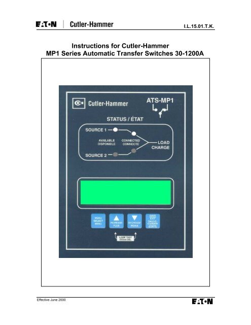
<strong>Instructions</strong> <strong>for</strong> <strong>Cutler</strong>-<strong>Hammer</strong><br />
<strong>MP1</strong> <strong>Series</strong> <strong>Automatic</strong> <strong>Transfer</strong> Switches 30-1200A
I.L.15.01.T.K. Page i<br />
Effective June 2000<br />
Table of Contents<br />
1. WARRANTY ........................................................................................................................................ 1<br />
2. RECEIVING, HANDLING AND STORAGE ................................................................................... 1<br />
2.1 RECEIVING ...................................................................................................................................... 1<br />
2.2 HANDLING....................................................................................................................................... 2<br />
2.3 STORAGE......................................................................................................................................... 2<br />
3. INTRODUCTION ................................................................................................................................ 3<br />
3.1 SAFETY PRECAUTIONS .................................................................................................................... 3<br />
3.2 GENERAL DESCRIPTION................................................................................................................... 3<br />
3.2.1 Type A..................................................................................................................................... 3<br />
3.2.2 Type B..................................................................................................................................... 3<br />
3.3 DESCRIPTION OF OPERATION........................................................................................................... 4<br />
3.4 DEFINITIONS.................................................................................................................................... 4<br />
4. EQUIPMENT DESCRIPTION........................................................................................................... 5<br />
4.1 “F-FRAME” AUTOMATIC TRANSFER SWITCH.................................................................................. 5<br />
4.2 “K, L, M, N-FRAME” HORIZONTAL AUTOMATIC TRANSFER SWITCH............................................. 5<br />
4.3 TABLE 1 - SYSTEMS COORDINATION INFORMATION – ...................................................... 6<br />
5. PERFORMANCE SPECIFICATIONS.............................................................................................. 7<br />
6. DESCRIPTION OF OPERATION..................................................................................................... 8<br />
6.1 INPUT PUSHBUTTONS ...................................................................................................................... 8<br />
6.2 PROGRAM MODE............................................................................................................................. 8<br />
6.2.1 Password ................................................................................................................................ 8<br />
6.2.2 Setpoints Menu ....................................................................................................................... 8<br />
6.3 LAMP TEST...................................................................................................................................... 9<br />
6.4 SERIAL CONNECTION ...................................................................................................................... 9<br />
6.5 LED OUTPUTS ................................................................................................................................9<br />
6.6 INPUT CONTACT DESCRIPTIONS ...................................................................................................... 9<br />
6.7 OUTPUT CONTACT DESCRIPTIONS................................................................................................. 10<br />
7. OPERATION VOLTAGE AND MEASUREMENT....................................................................... 10<br />
7.1 <strong>MP1</strong> .............................................................................................................................................. 10<br />
7.2 <strong>MP1</strong>-E .......................................................................................................................................... 10<br />
8. OPTIONS AND SETPOINTS ........................................................................................................... 11<br />
8.1 <strong>MP1</strong> SERIES CONTROLLER OPTIONS ............................................................................................. 11<br />
8.2 EXTERNAL OPTIONS...................................................................................................................... 13<br />
9. PROGRAM SETPOINTS MENU..................................................................................................... 15<br />
10. SUMMARY OF OPTIONS ...........................................................................................................16<br />
11. TROUBLESHOOTING................................................................................................................. 17<br />
12. MAINTENANCE ........................................................................................................................... 18
I.L.15.01.T.K. Page 1<br />
1. Warranty<br />
The Seller warrants that the Product<br />
manufactured by it will con<strong>for</strong>m to Seller’s<br />
applicable specifications and be free from<br />
failure due to defects in workmanship and<br />
material <strong>for</strong> a period of one (1) year from the<br />
date of shipment. In the event that a Product<br />
fails to comply with the <strong>for</strong>egoing warranty<br />
Seller will, at its option, either (a) repair or<br />
replace the defective Product, or defective<br />
part or component thereof, F.O.B. Seller’s<br />
facility freight prepaid, or (b) credit Buyer <strong>for</strong><br />
the purchase price of the Product. All<br />
warranty claims shall be made promptly in<br />
writing. Seller requires all non-con<strong>for</strong>ming<br />
Product be returned at Seller’s expense <strong>for</strong><br />
evaluation unless specifically stated<br />
otherwise in writing by Seller This warranty<br />
does not cover failure or damage due to<br />
storage, installation, operation or<br />
maintenance not in con<strong>for</strong>mance with<br />
Seller's recommendations and industry<br />
standard practice or due to accident,<br />
misuse, abuse or negligence. This warranty<br />
does not cover reimbursement <strong>for</strong> labour,<br />
gaining access, removal, installation,<br />
temporary power or any other expenses<br />
which may be incurred in connection with<br />
repair or replacement. This warranty does<br />
not apply to Product not manufactured by<br />
Seller. Seller limits itself to extending the<br />
same warranty it receives from the supplier.<br />
Limitation of Liability<br />
The remedies of the Buyer set <strong>for</strong>th herein<br />
are exclusive and are the sole remedies <strong>for</strong><br />
any failure of Seller to comply with its<br />
obligations hereunder. In no event shall<br />
Seller be liable in contract, in tort (including<br />
negligence or strict liability), extracontractually,<br />
or otherwise <strong>for</strong> damage to<br />
property or equipment other than the<br />
Product sold hereunder, loss of profits or<br />
revenue, loss of use of Product, cost of<br />
capital, claims of customers of the Buyer, or<br />
any special, indirect, incidental or<br />
consequential damage whatsoever. The<br />
total cumulative liability of Seller arising or<br />
related to this contract whether the claims<br />
are based in contract, in tort (including<br />
negligence or strict liability), extracontractually,<br />
or otherwise, shall not exceed<br />
the price of the Product or Service on which<br />
such liability is based.<br />
Effective June 2000<br />
2. Receiving, Handling and<br />
Storage<br />
2.1 Receiving<br />
Every ef<strong>for</strong>t is made to insure that transfer<br />
switch equipment arrives at its destination<br />
undamaged and ready <strong>for</strong> installation.<br />
Crating and packing is designed to protect<br />
internal components as well as the<br />
enclosure. <strong>Transfer</strong> switch enclosures are<br />
skid mounted and suited <strong>for</strong> <strong>for</strong>klift<br />
movement. Care should be exercised,<br />
however, to protect the equipment from<br />
impact at all times. Do not remove protective<br />
packaging until the equipment is ready <strong>for</strong><br />
installation. When transfer switch<br />
equipment reaches its destination, the<br />
customer should inspect the shipping<br />
container <strong>for</strong> any obvious signs of rough<br />
handling and/or external damage incurred<br />
during the transportation phase.<br />
Record any external and internal damage<br />
observed <strong>for</strong> reporting to the transportation<br />
carrier. Call the carriers concerned at once<br />
<strong>for</strong> inspection, and request an inspection<br />
report. Do not write to us first – notify the<br />
carrier instead. If this precaution is not<br />
taken we cannot assist you in recovering the<br />
amount of the claim against the carrier. All<br />
claims should be as specific as possible and<br />
include shop order (S.O.#) and general<br />
order numbers (G.O.#).<br />
A shipping label is affixed to the top of the<br />
shipping container which includes a variety<br />
of equipment and customer in<strong>for</strong>mation,<br />
such as General Order Number (G.O.#) and<br />
Catalog Number (Cat.#). Make certain that<br />
this in<strong>for</strong>mation matches other shipping<br />
paper in<strong>for</strong>mation.<br />
Each transfer switch enclosure is bolted<br />
through its top and bottom mounting holes to<br />
a rigid wooden pallet. The pallet is open at<br />
two ends <strong>for</strong> movement by a <strong>for</strong>k lift. Heavyduty<br />
cardboard surrounds the enclosure. A<br />
corrugated cardboard protector covers the<br />
entire top of the enclosure with additional<br />
cardboard protectors over the indicating<br />
lights. The shipment is secured and further<br />
protected with shrink wrap. Do not discard<br />
the packing material until the equipment is<br />
ready <strong>for</strong> installation.<br />
Once the top packaging is removed from the<br />
shipment, the enclosure door can be<br />
opened. A paper envelope of documents will
Page 2 I.L.15.01.T.K.<br />
be found within the enclosure, usually<br />
attached to the inside of the door. Important<br />
documents, such as test reports, wiring<br />
diagrams, and appropriate instruction<br />
leaflets, are enclosed within the envelope<br />
and should be filed in a safe place.<br />
2.2 Handling<br />
As previously mentioned, transfer switch<br />
equipment is packaged <strong>for</strong> <strong>for</strong>klift<br />
movement. Protect the equipment from<br />
impact at all times and do not double stack.<br />
Once the equipment is in the installation<br />
location and ready to be installed, packaging<br />
material can be removed. Once the<br />
enclosure is unbolted from the wooden<br />
pallet, it can be hand moved to its<br />
installation position. Two lifting lugs on the<br />
top of the enclosure are provided as<br />
standard on switches from 200-1200 Amps<br />
to facilitate installation.<br />
2.3 Storage<br />
Although well packaged, this equipment is<br />
not suitable <strong>for</strong> storage outdoors. The<br />
equipment warranty will not be applicable if<br />
there is evidence of outdoor storage. If the<br />
equipment is to be stored indoors <strong>for</strong> any<br />
period of time, it should be stored with its<br />
protective packaging material in place.<br />
Protect the equipment at all times from<br />
excessive moisture, construction dirt,<br />
corrosive conditions and other<br />
contaminants. It is strongly suggested that<br />
the package protected equipment be stored<br />
in a climate controlled environment of -20° to<br />
30°C with a relative humidity of 80% or less.<br />
Do not, under any circumstances, stack<br />
other equipment on top of a transfer switch<br />
equipment enclosure, whether packaged or<br />
not.<br />
Effective June 2000
I.L.15.01.T.K. Page 3<br />
3. Introduction<br />
This technical document is intended to cover<br />
most aspects associated with the<br />
installation, application, operation and<br />
maintenance of the ATS-<strong>MP1</strong> and ATS-<br />
<strong>MP1</strong>-E series controller. It is provided as a<br />
guide <strong>for</strong> authorized and qualified personnel<br />
only in the selection and application of an<br />
<strong>Automatic</strong> <strong>Transfer</strong> Switch with the <strong>Cutler</strong>-<br />
<strong>Hammer</strong> ATS-<strong>MP1</strong> series controller. Please<br />
refer to the specific WARNING and<br />
CAUTION in Section 3.1 be<strong>for</strong>e proceeding.<br />
If the purchaser requires further in<strong>for</strong>mation<br />
regarding a particular installation, application<br />
or maintenance activity, a <strong>Cutler</strong>-<strong>Hammer</strong><br />
representative should be contacted.<br />
3.1 Safety Precautions<br />
All safety codes, safety standards and/or<br />
regulations must be strictly observed in the<br />
installation, operation and maintenance of<br />
this device.<br />
WARNING<br />
THE WARNINGS AND CAUTIONS<br />
INCLUDED AS PART OF THE<br />
PROCEDURAL STEPS IN THIS<br />
DOCUMENT ARE FOR PERSONNEL<br />
SAFETY AND PROTECTION OF<br />
EQUIPMENT FROM DAMAGE. AN<br />
EXAMPLE OF A TYPICAL WARNING<br />
LABEL HEADING IS SHOWN IN<br />
REVERSE TYPE TO FAMILIARIZE<br />
PERSONNEL WITH THE STYLE OF<br />
PRESENTATION. THIS WILL HELP TO<br />
INSURE THAT PERSONNEL ARE ALERT<br />
TO WARNINGS, WHICH MAY APPEAR<br />
THROUGHOUT THE DOCUMENT.<br />
CAUTION<br />
COMPLETELY READ AND UNDERSTAND<br />
THE MATERIAL PRESENTED IN THIS<br />
DOCUMENT BEFORE ATTEMPTING<br />
INSTALLATION, OPERATION OR<br />
APPLICATION OF THE EQUIPMENT. IN<br />
ADDITION, ONLY QUALIFIED PERSONS<br />
SHOULD BE PERMITTED TO PERFORM<br />
ANY WORK ASSOCIATED WITH THE<br />
EQUIPMENT. ANY WIRING<br />
INSTRUCTIONS PRESENTED IN THIS<br />
DOCUMENT MUST BE FOLLOWED<br />
PRECISELY. FAILURE TO DO SO COULD<br />
CAUSE PERMANENT EQUIPMENT<br />
DAMAGE.<br />
Effective June 2000<br />
3.2 General Description<br />
CSA Standard C22.2 No. 178-1978 defines<br />
an automatic transfer switch as, “self acting<br />
equipment <strong>for</strong> transferring one or more load<br />
conductor connections from one power<br />
source to another.” The same Standard also<br />
gives definitions <strong>for</strong> type A and type B<br />
automatic transfer switches. “<strong>Transfer</strong> switch<br />
type A means an automatic transfer switch<br />
that does not employ integral overcurrent<br />
devices.” “<strong>Transfer</strong> switch, type B means an<br />
automatic transfer switch that (does) employ<br />
integral overcurrent protection.” <strong>Cutler</strong>-<br />
<strong>Hammer</strong> automatic transfer switches are<br />
available in both types.<br />
3.2.1 Type A<br />
Type A are equipped with special<br />
instantaneous magnetic only interrupters.<br />
The trip settings of these special interrupters<br />
are set (and fixed) at higher than standard<br />
values. They are intended to trip only if the<br />
upstream protective device fails to clear a<br />
fault. Incorporating these special magnetic<br />
only interrupters, a type A automatic transfer<br />
switch operates in exactly the same way as<br />
a transfer switch not having this feature. In<br />
the event that both devices trip, the control<br />
circuitry will automatically initiate transfer to<br />
the alternate source. The transfer operation<br />
will reset the “tripped” magnetic only<br />
interrupter.<br />
3.2.2 Type B<br />
Type B switches are equipped with standard<br />
moulded case circuit breakers with standard<br />
thermal-magnetic trip units that will provide<br />
the required over-load and short circuit<br />
protection. Type B switches can also be built<br />
using electronic trip units, which gives the<br />
ability to include ground fault tripping, as<br />
well as overload (long and short time) and<br />
short circuit protection (instantaneous). For<br />
application in<strong>for</strong>mation or assistance with<br />
type B switches, refer to <strong>Cutler</strong>-<strong>Hammer</strong>.<br />
For the remainder of this manual, the<br />
switching devices employed in the switch<br />
shall be referred to as breakers. This can<br />
imply either magnetic-trip only moulded case<br />
switches (MCS), or moulded case circuit<br />
breakers (MCCB) with overcurrent trip units.
Page 4 I.L.15.01.T.K.<br />
3.3 Description of Operation<br />
The <strong>Cutler</strong>-<strong>Hammer</strong> <strong>Automatic</strong> <strong>Transfer</strong><br />
Switch provides automatic transfer of an<br />
electrical load to a standby power supply in<br />
the event of drop or loss of voltage of any or<br />
all phases of the normal power supply. Upon<br />
the restoration of the normal supply, the<br />
electrical load is automatically retransferred<br />
to the normal power supply. The mechanism<br />
provides a positive mechanical interlock to<br />
prevent both breakers being closed at the<br />
same time. The mechanism is also designed<br />
to leave both breakers trip free in the closed<br />
position, permitting incorporation of thermal<br />
and short-circuit protection in either or both<br />
breakers. In Type B switches, an alarm<br />
switch contact is supplied. This contact is<br />
connected to the controller to lock the motor<br />
circuit out of operation when the breaker(s)<br />
trip on an overload or short-circuit condition.<br />
Then the breaker has to be manually reset.<br />
<strong>Instructions</strong> <strong>for</strong> the reset procedure are<br />
located on the front of the operating<br />
mechanism.<br />
3.4 Definitions<br />
With respect to their use in this document<br />
and as they relate to automatic transfer<br />
switch operation, the following terminology is<br />
defined:<br />
Available – A source is defined as<br />
“available” when it is within all undervoltage /<br />
overvoltage / underfrequency /<br />
overfrequency setpoint ranges <strong>for</strong> the<br />
nominal voltage and frequency setting.<br />
Fails – A source is defined as “failed” when<br />
it is outside of any undervoltage /<br />
overvoltage / underfrequency /<br />
overfrequency setpoint ranges <strong>for</strong> the<br />
nominal voltage and frequency setting <strong>for</strong> a<br />
time exceeding 0.5 seconds.<br />
Failsafe – Refers to the condition whereby<br />
the transfer switch is connected to the<br />
emergency source. In the event that the<br />
emergency source fails with normal source<br />
available an immediate retransfer to normal<br />
source shall occur.<br />
<strong>Transfer</strong> – A “transfer” is defined as the<br />
automatic operation under a normal source<br />
failure of switching the Load from Normal<br />
Source to the Emergency Source.<br />
Retransfer – A “retransfer” is defined as the<br />
automatic operation under Normal Source<br />
reappearance of switching the Load from<br />
Emergency Source to Normal Source.<br />
Effective June 2000
I.L.15.01.T.K. Page 5<br />
4. Equipment Description<br />
4.1 “F-Frame” <strong>Automatic</strong><br />
<strong>Transfer</strong> Switch<br />
Rated 30 amperes through 150 amperes at<br />
600 Volts AC and 200A at 240V maximum,<br />
50 or 60 Hertz. The mechanism is a lever<br />
operated device controlled by a 120 volt<br />
unidirectional motor. The transfer motor<br />
drives a cam that in turn operates a steel<br />
lever by sliding a pin along a slot in the back<br />
of the lever. The lever, in turn, operates the<br />
two breaker handles. There are two micro<br />
switches (NS/x, ES/x) inside the breakers<br />
that are operated by the breaker’s main<br />
contacts to provide switch status indication<br />
to the automatic controller. The switch has<br />
three operating positions. They are: the<br />
normal breaker closed and the emergency<br />
breaker open, the emergency breaker<br />
closed and the normal breaker open or both<br />
the normal and emergency breakers open.<br />
The normal and emergency breakers can<br />
never both be closed at the same time.<br />
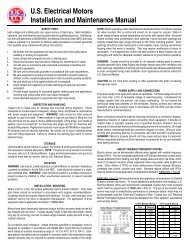
Figure 1 -Typical Power Panel <strong>for</strong> 30-<br />
200A models<br />
The F-Frame switch can also be easily<br />
manually operated. Remove the thumb<br />
screw on the operating handle and place it<br />
in a safe location. Then the lever can be<br />
manually operated <strong>for</strong> whatever position<br />
desired without interference by the<br />
automatic control. For automatic control<br />
again, simply align the hole in the motor arm<br />
with the slot in the operating arm and<br />
replace the thumb screw. The various<br />
automatic control components are described<br />
beginning in Section 6 titled “Description of<br />
Operation”.<br />
Effective June 2000<br />
4.2 “K, L, M, N-Frame” Horizontal<br />
<strong>Automatic</strong> <strong>Transfer</strong> Switch<br />
A complete line rated from 200 through<br />
1200 * Amperes at 600 Volts AC 50 or 60<br />
Hertz.<br />
The transfer mechanism consists of the<br />
transfer motor, a gear train and two breaker<br />
operating cams.<br />
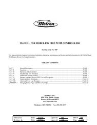
Figure 2 - Spur Gear Meshing<br />
Relationship (Bottom View of Top Cover)<br />
The transfer motor drives the centre gear<br />
which in turn operates the two secondary<br />
gears. There is a projection in the secondary<br />
gears which slides in a groove in the<br />
operating cams, moving the cams from side<br />
to side. The breaker handles are set inside<br />
two outer guides of the cam and are also<br />
moved from side to side. There are two<br />
micro switches (NS/x, ES/x) inside the<br />
breakers that are operated by the breaker’s<br />
main contacts to provide switch status<br />
indication to the automatic controller.<br />
The Horizontal type transfer switch has<br />
three operating positions, the normal<br />
breaker closed and the emergency breaker<br />
open, the emergency breaker closed and<br />
the normal breaker open or both the normal<br />
and the emergency breakers open but never<br />
both the normal and emergency breakers<br />
closed at the same time. The switch is also<br />
easy to operate manually. Simply remove<br />
the motor disconnect plug and turn the<br />
operating handle on the front of the transfer<br />
mechanism in a counter clockwise direction<br />
until you hear the breakers operated and the<br />
indicator is in the desired position. There will<br />
be no interference from the microprocessor<br />
control. For automatic control, reconnect<br />
the transfer motor plug and the transfer<br />
switch will seek the source with power<br />
available.<br />
* A 1200A Switch in the Horizontal design is provided as a<br />
type “B” switch with overcurrent protection (Option 16N)<br />
and rated <strong>for</strong> 80% continuous current.
Page 6 I.L.15.01.T.K.<br />
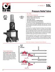
Figure 3 - Typical Power Panel <strong>for</strong> 200-1200A models<br />
4.3 Table 1 - SYSTEMS COORDINATION INFORMATION –<br />
WITHSTAND, CLOSING & INTERRUPTING RATINGS<br />
ATS<br />
Ampere<br />
Rating<br />
Ratings when used with upstream<br />
breaker (kA)<br />
240V 480V 600V<br />
Ratings when used with upsteam<br />
fuse (kA)<br />
Max Fuse Fuse<br />
600V<br />
Rating Type<br />
30 100 65 25 200 J,T 200<br />
70 100 65 25 200 J,T 200<br />
100 100 65 25 200 J,T 200<br />
150 100 65 25 400 J,T 200<br />
225 100 65 35 400 J,T 200<br />
300 100 65 35 400 J,T 200<br />
400 100 65 35 600 J,T 200<br />
600 65 50 25 800/1200 J,T 100/200<br />
800 65 50 25 1200/1600 L 100/200<br />
1000 65 50 25 1600 L 200<br />
1200 65 50 25 1600 L 200<br />
Effective June 2000
I.L.15.01.T.K. Page 7<br />
5. Per<strong>for</strong>mance Specifications<br />
The per<strong>for</strong>mance specifications <strong>for</strong> the ATS-<strong>MP1</strong> Controller Board are given in Table 2:<br />
Table 2 – Per<strong>for</strong>mance Specifications<br />
Input Control Voltage (50-150)% of V(IN,RMS) 50/60 Hz<br />
Voltage Measurements of: Normal Source VAB Emergency Source VAB<br />
Normal Source VBC<br />
Normal Source VCA<br />
Emergency Source VBC<br />
Emergency Source VCA<br />
Voltage Measurement Range: 0 to 360 VAC RMS (50/60Hz) – <strong>MP1</strong><br />
0 to 750 VAC RMS (50/60Hz) – <strong>MP1</strong>-E<br />
Voltage Measurement Accuracy: ± 2% of reading over the monitoring range<br />
Frequency Measurements of: Normal Source (S1), Emergency Source (S2)<br />
Frequency Measurement Range: 40 Hz to 70 Hz<br />
Frequency Measurement Accuracy ± 0.3 Hz over the measurement range<br />
Undervoltage Dropout Range: 50% to 97% of the nominal system voltage<br />
Undervoltage Pickup Range: (Dropout +2%) to 99% of the nominal system voltage<br />
Overvoltage Dropout Range: 105% to 120% of the nominal system voltage<br />
Overvoltage Pickup Range: 103% to (Dropout –2%) of the nominal system voltage<br />
Underfrequency Dropout Range: 90% to 97% of the nominal system frequency<br />
Underfrequency Pickup Range: (Dropout + 1Hz) to 99% of the nominal system frequency<br />
Overfrequency Dropout Range: 103% to 110% of the nominal system frequency<br />
Overfrequency Pickup Range: 101% to (Dropout – 1Hz) of the nominal system frequency<br />
Operating Temperature Range -20°C to + 70°C<br />
Storage Temperature Range -35°C to + 85°C<br />
Operating Humidity 0 to 95% relative humidity (non-condensing)<br />
Generator Start Relay 5A, 1/6 HP @ 250VAC<br />
5A @ 30VDC with a 30W maximum load<br />
Alarm Relay 10A, 1-3 HP @ 250VAC<br />
10A @ 30VDC<br />
Table 3 - Applicable Test Standards<br />
UL 991<br />
Canadian Standards Association Con<strong>for</strong>mance (CSA)<br />
UL 1008 / CSA 22.2 No 178.22<br />
Dielectric test<br />
FCC Part 15<br />
Conducted/Radiated Emissions (Class A)<br />
CISPR 11<br />
Conducted/Radiated Emissions (Class A)<br />
IEC 1000-2<br />
Electrostatic Discharge test<br />
IEC 1000-3<br />
Radiated Susceptibility tests<br />
IEC 1000-4<br />
Fast Transient tests<br />
IEC 1000-5<br />
Surge Withstand tests<br />
Effective June 2000
Page 8 I.L.15.01.T.K.<br />
6. Description of Operation<br />
The primary functions of the ATS-<strong>MP1</strong><br />
controller is to accurately monitor two power<br />
sources and provide the necessary<br />
intelligence to operate a transfer switch in an<br />
appropriate and timely manner. The ATS-<br />
<strong>MP1</strong> uses proven microprocessor-based<br />
technology that provides a high reliability<br />
and accuracy <strong>for</strong> all voltage sensing and<br />
timing functions. The input function consists<br />
of keypad type pushbutton inputs (4 in total).<br />
In addition, effectively a fifth user input<br />
exists via a rear located PC type serial port<br />
connection to be used in factory and field<br />
programming of options and setpoints.<br />
Outputs functions consist of LED outputs (4<br />
total) and a two line 16-character<br />
alphanumeric LCD display output.<br />
6.1 Input Pushbuttons<br />
There are four front panel membrane type<br />
pushbuttons. Pushbuttons accomplish their<br />
function when pressed and released.<br />
Menu Select<br />
The user can scroll through the available<br />
display in<strong>for</strong>mation. Pushing the Menu<br />
Select key will scroll through the voltage and<br />
frequency of each source. When in the<br />
setpoints menu, pushing the Menu Select<br />
key will scroll the user through each of the<br />
setpoint options in sequence.<br />
Increase (Increments specific variable<br />
range)<br />
When the user initiates program mode, each<br />
press of the Increase key will increase the<br />
displayed value by one. The Increase<br />
pushbutton will continue to scroll if it is<br />
pressed and not released.<br />
Decrease (Decrements specific variable<br />
range)<br />
When the user initiates program mode, each<br />
press of the Decrease key will decrease the<br />
displayed value by one. The Decrease<br />
pushbutton will continue to scroll if it is<br />
pressed and not released.<br />
Save/Exit<br />
When in program mode and the user has<br />
selected the desired setpoints <strong>for</strong> nominal<br />
operation, pressing the save button will store<br />
all of the settings.<br />
The following are three modes of operation<br />
that are easily accessed via the front panel<br />
keys:<br />
6.2 Program Mode<br />
This mode of operation is used only to<br />
change setpoint values of existing operating<br />
parameters (standard and programmed<br />
options).<br />
Program mode is achieved by depressing<br />
the Menu Select key and Save (Exit) key<br />
simultaneously <strong>for</strong> five-second duration.<br />
ENTER PASSWORD<br />
The LCD will then display the phrase “Enter<br />
Password.”<br />
6.2.1 Password<br />
To enter the program mode, the ATS-<strong>MP1</strong><br />
requires a password to prevent unauthorized<br />
persons from modifying setpoint values.<br />
The password is factory set to a combination<br />
of 4 depressions of the Menu Select, up,<br />
and down arrow keys in sequence. The<br />
password set at the factory is contained on a<br />
sticker mounted on the rear of the controller.<br />
Factory Password:<br />
Decrease, Increase, Menu, Decrease<br />
Once the correct password is entered, the<br />
password may be changed by the user at<br />
the prompt “Change Password?” It is<br />
advisable that if changed, the password be<br />
set to either a combination that is easily<br />
remembered, and also written in the<br />
appropriate space on the sticker. The<br />
enclosure door can be padlocked to prevent<br />
unauthorized persons from gaining<br />
knowledge of the password.<br />
6.2.2 Setpoints Menu<br />
When in the setpoints menu, by depressing<br />
the Menu Select key, the user can scroll<br />
through the operating parameters at any<br />
time adjusting any setpoint values using the<br />
Effective June 2000
I.L.15.01.T.K. Page 9<br />
Increase or Decrease keys. Once all of the<br />
setpoint operating parameters have been<br />
entered, the user may save the new setpoint<br />
options by depressing the Save (Exit) key.<br />
Once this is completed, the controller<br />
acknowledges the setpoint values have<br />
been programmed by displaying the<br />
message “Setpoints Programmed.”<br />
6.3 Lamp Test<br />
(Increase and Decrease Simultaneously)<br />
Pressing the Increase and Decrease buttons<br />
simultaneously will cause the all LEDS to<br />
illuminate <strong>for</strong> a minimum of ten seconds.<br />
During this lamp test the LCD displays the<br />
message “Lamp Test.”<br />
6.4 Serial Connection<br />
A serial input connection is accessible from<br />
the rear of the ATS-<strong>MP1</strong> controller. This<br />
input is used <strong>for</strong> factory and field<br />
programmability of options and setpoints. It<br />
communicates to a standard PC or laptop<br />
via serial communication. A field update<br />
software package <strong>for</strong> Windows ® based PCs<br />
is available. This software allows the user to<br />
adjust and view controller setpoints, and add<br />
additional options to the controller with a<br />
factory authorized code. Contact <strong>Cutler</strong>-<br />
<strong>Hammer</strong> <strong>for</strong> further details.<br />
6.5 LED Outputs<br />
Normal Source Available<br />
This red LED is lit when the normal source<br />
meets the user programmed setpoint<br />
criteria.<br />
Normal Source Connected<br />
This red LED displays the status of the<br />
transfer switch position. It illuminates when<br />
the normal source is available and the<br />
transfer switch is in normal position.<br />
Indication of the transfer switch in normal<br />
position is accomplished by sensing the<br />
closed A-contact of the normal breaker<br />
auxiliary.<br />
Emergency Source Available<br />
This red LED is lit when the emergency<br />
source meets the user programmed setpoint<br />
criteria.<br />
Emergency Source Connected<br />
This red LED displays the status of the<br />
transfer switch position. It illuminates when<br />
Effective June 2000<br />
the emergency source is available and the<br />
transfer switch is in emergency position.<br />
Indication of the transfer switch in<br />
emergency position is accomplished by<br />
sensing the closed A-contact of the<br />
emergency breaker auxiliary.<br />
6.6 Input Contact Descriptions<br />
The control outputs of the ATS-<strong>MP1</strong><br />
controller are wetted DC contacts.<br />
Source 1 Auxiliary Closed<br />
This contact is hard-wired to the normal<br />
breaker auxiliary contact that is closed when<br />
the normal breaker is closed (A-contact).<br />
Source 2 Auxiliary Closed<br />
This contact is hard-wired to the emergency<br />
breaker auxiliary contact that is closed when<br />
the emergency breaker is closed (Acontact).<br />
Source 1 and Source 2 Lockout<br />
(Requires Option 16)<br />
This contact is hard-wired to the normal<br />
and/or emergency breaker lockout (bell<br />
alarms) contacts that close when one of the<br />
breaker has tripped due to an overcurrent<br />
condition or fault current condition. Closure<br />
of this contact inhibits any transfer from<br />
occurring and the message<br />
“*** LOCKOUT ***” will appear on the LCD.<br />
Bypass Time Delay(s)<br />
(Requires Option 8)<br />
Closure of this contact will bypass the<br />
programmed values <strong>for</strong> either or both of the<br />
TDNE and TDEN timer setpoints, depending<br />
upon which option has been selected<br />
Go To Neutral (Services Disconnect)<br />
Closure of this contact <strong>for</strong>ces the controller<br />
to switch to the neutral position thereby<br />
disconnecting the load from both sources.<br />
Enabling of this function <strong>for</strong>ces a minimum<br />
neutral position time as determined by the<br />
programmed TDN setpoint.<br />
Test/Area Protection<br />
Closure of this contact will cause the<br />
controller to initiate a transfer to Source 2 if<br />
the transfer switch is in Source 1 position.<br />
Opening of this contact will cause the<br />
controller to initiate a transfer to Source 1 if<br />
the transfer switch is in Source 2 position.
Page 10 I.L.15.01.T.K.<br />
Preferred Source – <strong>MP1</strong>-E Only<br />
Requires Option 10<br />
This feature permits the selection of either<br />
source (1 or 2) as the preferred or normal<br />
source. The normal source is the source that<br />
the switch always looks to <strong>for</strong> availability so<br />
that it can transfer to it.<br />
Manual Return To Normal – <strong>MP1</strong>-E Only<br />
Requires Option 29<br />
A manual operated momentary contact<br />
(normally open) operates in conjunction with<br />
the Manual Return to Normal option to<br />
replace the TDEN timing function. With the<br />
manual mode set, closure of this contact will<br />
prompt an immediate transfer bypassing the<br />
TDEN time delay. This ensures that a retransfer<br />
occurs only at the discretion of the<br />
operator.<br />
6.7 Output Contact Descriptions<br />
The control outputs of the ATS-<strong>MP1</strong><br />
controller are dry relay contacts. These<br />
relays are comprised of a latching Form A<br />
relay to provide the Generator Start Relay<br />
contact, a Form A contact <strong>for</strong> the <strong>Transfer</strong><br />
Motor Relay contact, and a Form C relay <strong>for</strong><br />
an alarm output. The dielectric rating <strong>for</strong><br />
each output is a minimum of 1500 VAC<br />
Generator Start Relay<br />
This latching relay is the generator start<br />
relay <strong>for</strong> system configurations that employ<br />
a generator on the emergency source. This<br />
relay employs a Form A contact <strong>for</strong> closure<br />
of the generator start circuit. The Generator<br />
start relay is rated <strong>for</strong> 5A @ 30VDC with a<br />
30W maximum load.<br />
<strong>Transfer</strong> Motor Relay<br />
This is a Form A contact is used to close the<br />
electrical path of the transfer motor control<br />
circuit. Closure of this contact will initiate a<br />
transfer from the normal source to<br />
emergency source and from emergency<br />
source to normal source as required per<br />
normal transfer switch operation.<br />
Alarm Relay<br />
The full Form C contact of this relay may be<br />
wired to an alarm enunciator panel to<br />
indicate problem with the ATS. This relay is<br />
normally energized to indicate an absence<br />
of an alarm state. De-energization of this<br />
relay indicates the presence of an alarm<br />
condition. An alarm condition will occur if a<br />
transfer has been initiated but is never<br />
completed (This may indicate that<br />
something is wrong with the motor or<br />
transfer mechanism). The alarm contact<br />
will also change state if the controller<br />
detects a phase reversal condition between<br />
the normal and emergency sources. The<br />
controller will also inhibit transfer on this<br />
condition<br />
Pre-<strong>Transfer</strong> Relay (<strong>MP1</strong>-E Only)<br />
Requires Option 35<br />
This feature provides <strong>for</strong> the control of an<br />
external 120V instant relay with 2 Form C<br />
contacts to remotely signal that a re-transfer<br />
is about to take place.<br />
7. Operation Voltage and<br />
Measurement<br />
Both the <strong>MP1</strong> and <strong>MP1</strong>-E operate on single<br />
and three phase systems with selectable<br />
frequency settings of 50Hz or 60Hz.<br />
7.1 <strong>MP1</strong><br />
This <strong>MP1</strong> operates directly from the line<br />
sensing inputs of the two different sources<br />
(normal and emergency). The nominal<br />
operating system inputs are from 110VAC-<br />
240VAC. The standard system assumes<br />
that neutral is available and that the transfer<br />
motor can there<strong>for</strong>e be powered from an<br />
available 120 VAC source. If a neutral<br />
conductor is not available, a 120VAC supply<br />
is created by an external trans<strong>for</strong>mer.<br />
7.2 <strong>MP1</strong>-E<br />
The <strong>MP1</strong>-E provides the user with an<br />
enhanced feature set, and a wider range of<br />
voltage measurement, from 110VAC-<br />
600VAC. A high impedance resistive circuit<br />
is used in series with the voltage sensing<br />
inputs to reduce the voltage applied to the<br />
controller to comply with safety codes <strong>for</strong><br />
door-mounted devices. The power supply<br />
<strong>for</strong> the <strong>MP1</strong>-E requires a 120VAC source,<br />
provided by an external trans<strong>for</strong>mer.<br />
Effective June 2000
I.L.15.01.T.K. Page 11<br />
8. Options and Setpoints<br />
The options and setpoints are stored in nonvolatile<br />
memory. A standard option is<br />
enabled on every controller. Those<br />
designated as programmable can be added<br />
at the factory at the customer’s request<br />
(usually at an additional cost), or can be<br />
added in the field via PC software and/or an<br />
option key. Setpoint values are modified by<br />
using the pushbutton keys on the front panel<br />
or using the <strong>Cutler</strong>-<strong>Hammer</strong> ATS-Connect<br />
Field Update software.<br />
Effective June 2000<br />
NOTICE<br />
REFER TO BOTH THE FACTORY TEST<br />
SHEET, AND THE DRAWINGS THAT<br />
SHIPPED WITH THE TRANSFER SWITCH<br />
TO DETERMINE THE OPTIONS THAT<br />
ARE INSTALLED. AN OPTION WILL NOT<br />
BE FUNCTIONAL, NOR WILL THE<br />
PARAMETERS BE ADJUSTABLE<br />
THROUGH THE SETPOINTS MENU IF AN<br />
OPTION IS NOT ENABLED.<br />
8.1 <strong>MP1</strong> <strong>Series</strong> Controller<br />
Options<br />
Standard option - TDNE<br />
Time Delay Normal to Emergency<br />
Provides a time delay when transferring the<br />
normal source to the emergency source. To<br />
ensure stability of the emergency source.<br />
Timing begins when the emergency source<br />
becomes available.<br />
Standard option - TDES<br />
Time Delay Engine Start<br />
Delays the initiation of the engine start<br />
circuit in order to override momentary power<br />
outages or voltage fluctuations of the normal<br />
source. The TDES timer shall start when<br />
the normal source becomes unavailable. If<br />
the normal source becomes available while<br />
timing, the TDES timer shall reset. The<br />
controller can per<strong>for</strong>m the time delay engine<br />
start function without control power <strong>for</strong> 120<br />
seconds.<br />
Standard option - TDEN<br />
Time Delay Emergency to Normal<br />
Delays the transfer from the emergency<br />
source to the normal source to permit<br />
stabilization of the normal source be<strong>for</strong>e retransfer<br />
is made. Timing begins when the<br />
normal source becomes available.<br />
If the emergency source fails during timing<br />
<strong>for</strong> a period greater than 0.5 seconds,<br />
transfer to normal source is immediate. If<br />
the normal source fails during timing, the<br />
TDEN timer shall reset once the normal<br />
source becomes available again.<br />
Standard option - TDEC<br />
Time Delay Engine Cooldown<br />
Permits the generator to continue to run<br />
unloaded after retransfer to the normal<br />
source has occurred. Timing begins when<br />
the transfer to normal has been completed.<br />
Emergency Source Frequency/Voltage<br />
Sensing<br />
Continuously monitors the emergency<br />
source <strong>for</strong> one of the conditions listed below.<br />
When the emergency frequency and/or<br />
voltage is outside the dropout setpoints, the<br />
source will become unavailable. The<br />
source’s frequency and/or voltage will then<br />
have to be within the pickup setpoints to<br />
become available again.<br />
a) Emergency Source Undervoltage<br />
(Standard option)<br />
b) Emergency Source Underfrequency<br />
(Standard option)<br />
c) Emergency Source Overvoltage<br />
(Optional Feature)<br />
d) Emergency Source Overfrequency<br />
(Optional Feature)<br />
Normal Source Frequency/Voltage<br />
Sensing<br />
Continuously monitors the normal source <strong>for</strong><br />
out of range setpoint values. When the<br />
normal frequency and/or voltage is outside<br />
the dropout setpoints, the source will<br />
become unavailable. This will then prompt a<br />
transfer to the emergency source once it<br />
becomes available. The normal source’s<br />
frequency and/or voltage will then have to<br />
be within the pickup setpoints to become<br />
available again <strong>for</strong> a retransfer.<br />
a) Normal Source Undervoltage (Standard<br />
option)
Page 12 I.L.15.01.T.K.<br />
b) Normal Source Underfrequency<br />
(Optional Feature)<br />
c) Normal Source Overvoltage (Optional<br />
Feature)<br />
d) Normal Source Overfrequency<br />
(Optional Feature)<br />
Standard Option – Phase Reversal<br />
<strong>MP1</strong>-E Only<br />
The alarm contact will change state if the<br />
controller detects a phase reversal condition<br />
between the normal and emergency<br />
sources. The controller will also inhibit<br />
transfer on this condition.<br />
Standard Option - Plant Exerciser<br />
This option provides <strong>for</strong> automatic test<br />
operation of the generator. The interval is<br />
fixed at once per week with duration equal to<br />
the programmed engine test time (ERT).<br />
Two optional modes of plant exercising are<br />
available:<br />
a) No Load Exercise<br />
b) Load Exercising with failsafe<br />
If desired, this option can be disabled by<br />
choosing “No” at the “Plant Exerciser”<br />
prompt in the menu. Also if “---“ is chosen<br />
as the test day, the engine will not be<br />
exercised.<br />
Optional Feature 8 - Pushbutton Bypass<br />
of Time Delays (PBNE/PBEN)<br />
Enables the user to bypass TDNE or TDEN<br />
timer during a test or exercise. Pressing the<br />
external pushbutton shall cause the transfer<br />
switch to transfer to the normal and/or<br />
emergency source without a time delay.<br />
Three optional modes of bypassing are<br />
available:<br />
a) PBNE – Pushbutton Bypass Time Delay<br />
Normal to Emergency<br />
b) PBEN – Pushbutton Bypass Time Delay<br />
Emergency to Normal<br />
c) PBG – Pushbutton Bypass Time Delay<br />
Global (Both TDNE & TDEN)<br />
Optional Feature 10 - Preferred Source<br />
(PFR SRC) <strong>MP1</strong>-E Only<br />
Permits the selection of either source (1 or<br />
2) as the preferred source. The preferred<br />
source is the source that the <strong>MP1</strong>-E<br />
controller looks to <strong>for</strong> availability so that the<br />
transfer switch may remain in this position<br />
and supply the load with this source.<br />
The preferred source will be considered the<br />
same as the “normal” source and the<br />
alternate source will be considered the same<br />
as the “emergency” source. All time delays<br />
(e.g. TDNE, TDEN) will be a function of this<br />
feature and follow the preferred source.<br />
Three optional modes of Preferred Source<br />
Selection are programmable:<br />
PS1 – Source 1 is selected as preferred.<br />
Source 2 is the alternate source.<br />
PS2 – Source 2 is selected as preferred.<br />
Source 1 is the alternate source.<br />
PS0 – No Source is selected as preferred<br />
Note: If the preferred source feature is not<br />
programmed, Source 1 will default as the<br />
preferred source and Source 2 will default<br />
as the alternate source.<br />
If no sources are selected as preferred, the<br />
transfer switch will remain on any source<br />
that is available and meets the programmed<br />
set-point criteria. Moreover, in this mode of<br />
operation, the transfer switch will only<br />
transfer from Source 1 to Source 2 or from<br />
Source 2 to Source 1 if a failure occurs on<br />
the source that the transfer switch resides<br />
on. It should be noted that the preferred<br />
source contact is disabled when there is no<br />
preferred source selected. However, if the<br />
Area protection option is enabled and<br />
prompted, the controller will react by<br />
transferring to the appropriate source as<br />
described in the Area Protection feature.<br />
Optional Feature 26D - Test/Area<br />
Protection<br />
This feature provides <strong>for</strong> a remote customer<br />
contact. This option is always enabled in the<br />
controller, but as an option, terminal block<br />
connections may be provided <strong>for</strong> a remote<br />
signal.<br />
Closure of this contact will cause the<br />
controller to initiate a transfer to Source 2 if<br />
the transfer switch is in Source 1 position.<br />
Opening of this contact will cause the<br />
controller to initiate a transfer to Source 1 if<br />
the transfer switch on Source 2 position.<br />
This feature is typically used if it is known<br />
that there may be problems with the Normal<br />
Source such as an impending lightning<br />
storm, or the local utility per<strong>for</strong>ming<br />
maintenance in the area. The switch will<br />
Effective June 2000
I.L.15.01.T.K. Page 13<br />
remain on the emergency source until the<br />
external contact is opened, when user is<br />
certain that the threat of problems has<br />
passed. If the emergency source fails at<br />
any time when in the Area Protection mode,<br />
the switch will immediately transfer back to<br />
the Normal source if it is Available.<br />
The <strong>MP1</strong>-E controller allows the Test/Area<br />
protection input to be disabled if the user<br />
would like to prevent unauthorized users<br />
from using the test switch or input contact.<br />
Optional Feature 29 - Manual Return To<br />
Normal – <strong>MP1</strong>-E Only<br />
A manual operated momentary contact<br />
(normally open) operates in conjunction with<br />
the Manual Return to Normal option to<br />
replace the TDEN timing function. With the<br />
manual mode set, closure of this contact will<br />
prompt an immediate transfer bypassing the<br />
TDEN time delay. This ensures that a retransfer<br />
occurs only at the discretion of the<br />
operator.<br />
Optional Feature 32 - Time Delay Neutral<br />
Provides a time delay in the transfer switch<br />
neutral position when the load is transferred<br />
in one or both directions. This is to prevent<br />
excessive inrush currents due to out-ofphase<br />
switching of large inductive loads. If<br />
the TDN timer is programmed to 0 seconds,<br />
the transfer switch shall operate as if the<br />
TDN option is disabled. Three optional<br />
modes of Neutral Time Delay are available<br />
as programmable:<br />
(a) TDN(NE) – Time Delay Neutral (from<br />
Normal to Emergency)<br />
(b) TDN(EN) – Time Delay Neutral (from<br />
Emergency to Normal)<br />
(c) TDN(G) – Time Delay Neutral (Both<br />
directions)<br />
8.2 External Options<br />
There are also external options that may be<br />
installed in a <strong>Cutler</strong>-<strong>Hammer</strong> <strong>Automatic</strong><br />
<strong>Transfer</strong> Switch. A brief description is<br />
provided.<br />
Standard Feature 6D – 2 Position Test<br />
Selector Switch (TSS)<br />
Position 1 – “Auto”: The ATS will function<br />
normally, transferring to the emergency<br />
source when normal power is lost.<br />
Effective June 2000<br />
Position 2 – “Test”: The ATS will simulate<br />
the loss of the normal source. The switch<br />
will transfer to source 2 after the Time Delay<br />
Engine Start, and the TDNE has expired.<br />
The ATS will return to the normal position<br />
when the switch is return to “Auto”.<br />
Option 6G is identical to the Test Selector<br />
Switch except key operated. Key removable<br />
in “Auto” position.<br />
Standard Feature 6H – 4 Position Test<br />
Selector Switch (FPSS)<br />
Position 1 – “Auto”: The ATS will function<br />
normally, transferring to source 2 when<br />
normal power is lost.<br />
Position 2 – “Test”: The ATS will simulate<br />
the loss of the normal source. The switch<br />
will transfer to source 2 after the Time Delay<br />
Engine Start, and the TDNE has expired.<br />
The ATS will return to the normal position<br />
when the switch is returned to “Auto”.<br />
Position 3 – “Engine Start”: The engine start<br />
contacts will close, giving the genset a start<br />
signal. This position can be used to test the<br />
correct connection of the engine start<br />
terminals, or as a remote start. The<br />
controller with function normally and transfer<br />
to the emergency if normal power is lost.<br />
Position 4 – “Manual”: This will disconnect<br />
the transfer motor, and prevent transfers in<br />
either direction. The ATS can be transferred<br />
only by operating the manual transfer<br />
handle.<br />
Option 6J is identical to the Four Position<br />
Selector Switch except key operated. Key<br />
removable in “Auto” position.<br />
Optional Feature 12C – Normal<br />
Connected Pilot light.<br />
A green 30mm indication light indicates that<br />
the load is connected to the normal source.<br />
Optional Feature 12D –<br />
Emergency Connected Pilot light.<br />
A red 30mm indication light indicates that<br />
the load is connected to the emergency<br />
source.
Page 14 I.L.15.01.T.K.<br />
Optional Feature 12G –<br />
Normal Available Pilot light.<br />
A white 30mm indication light indicates that<br />
the normal source is available.<br />
Optional Feature 12H –<br />
Emergency Available Pilot light.<br />
A white 30mm indication light indicates that<br />
the emergency source is available.<br />
Optional Feature 14 – Auxiliary Relays<br />
120VAC instant relays labeled NRA (Normal<br />
Source) and ERA (Emergency Source)<br />
provide the user with up to six (6) <strong>for</strong>m C<br />
contacts <strong>for</strong> switch status indication. The<br />
relays are energized when power is<br />
available and the switch is currently<br />
connected to the source. The contacts are<br />
wired to terminal blocks beginning with<br />
number 501. See the schematic shipped<br />
with the unit <strong>for</strong> more detail.<br />
Optional Feature 15 – Auxiliary Contacts<br />
Auxiliary switches mounted inside the<br />
breakers follow the breaker position,<br />
regardless of power availability. The <strong>for</strong>m C<br />
contacts are wired to terminal blocks<br />
beginning with number 401. See the<br />
schematic shipped with the unit <strong>for</strong> more<br />
detail.<br />
Optional Feature 16 - Integral<br />
Overcurrent Protection<br />
Provides ovecurrent protection integral to<br />
the power switching device. The use of this<br />
option can, in many cases, eliminate the<br />
need <strong>for</strong> separate upstream,<br />
overcurrent/short-circuit protection. For<br />
safety purposes, this option includes a lockout<br />
function that prevents further automatic<br />
transfer operation until the appropriate<br />
source is manually reset. The <strong>MP1</strong><br />
controller will also read ***LOCKOUT*** on<br />
the display. See the front of the switch<br />
mechanism <strong>for</strong> instructions. (Note: Four<br />
pole transfer switches include overcurrent<br />
protection only on the three power poles)<br />
Optional Feature 18 – Metering and<br />
Communications<br />
Analog meters or <strong>Cutler</strong>-<strong>Hammer</strong> IQ<br />
metering devices can be installed to provide<br />
various metering functions. Refer to the<br />
appropriate instruction manuals that ship<br />
with the transfer switch <strong>for</strong> additional<br />
in<strong>for</strong>mation.<br />
Optional Feature 24 – Battery Charger<br />
A 5A trickle charger with DC output of 12V<br />
or 24V is mounted either inside the switch<br />
enclosure or supplied loose and externally<br />
mounted. Refer to the specific instruction<br />
manuals that ship with the transfer switch <strong>for</strong><br />
additional in<strong>for</strong>mation.<br />
Optional Feature 30 – Cranking Limiter<br />
An externally mounted timing relay,<br />
adjustable from 0-120 sec. The relay will<br />
interrupt the engine start circuit if voltage<br />
does not appear on the emergency source<br />
within the pre-selected time. When setting<br />
the time delay, make certain the TDES and<br />
the warm-up time of the genset is taken into<br />
account.<br />
Effective June 2000
I.L.15.01.T.K. Page 15<br />
9. Program Setpoints Menu<br />
This table is a guide to the program setpoints menu. An explanation is given <strong>for</strong> each prompt that<br />
will appear as the Menu Select key is pressed.<br />
Program Setpoint<br />
Display<br />
Setpoint Display Possibilities<br />
Explanation<br />
Lang: English, French Language the controller displays messages<br />
Current Day: Mon-Sun Current Day – requires to only be set once<br />
Current Hour: 0-23 Current Hour<br />
Current Min: 0-60 Current Min<br />
Nom.Volt: 110 VAC – 240 VAC<br />
110VAC – 600VAC<br />
System operating voltage<br />
Nom .Freq: 50Hz or 60Hz. System operating frequency<br />
Phases: 1 or 3 Single phase or Three Phase system<br />
TDNE: 0 sec. to 1800 sec. Time Delay Normal to Emergency<br />
TDES: 0 sec. to 120 sec. Time Delay Engine Start<br />
TDEN: 0 sec. to 1800 sec. Time Delay Emergency to Normal<br />
TDEC: 0 sec. to 1800 sec. Time Delay Engine Cooldown<br />
TDN: -none-, N to E, E to N, Time Delay in Neutral position. Can be<br />
global<br />
selected when transferring in one direction only<br />
or both<br />
TDN: 0 to 120 sec. Time Delay Neutral<br />
TPRE: 0 to 255 sec Pre-<strong>Transfer</strong> Time Delay<br />
N-UV-DO: 50% to 99% of nominal Source 1 Undervoltage Dropout (% of nominal)<br />
N-UV-PU: (dropout +2%) to 99% Source 1 Undervoltage Pickup (% of nominal)<br />
E-UV-DO: 50% to 99% Source 2 Undervoltage Dropout (% of nominal)<br />
E-UV-PU: (dropout +2%) to 99% Source 2 Undervoltage Pickup (% of nominal)<br />
N-OV-DO: 105% to 120% Source 1 Overvoltage Dropout (% of nominal)<br />
N-OV-PU: (dropout -2%) to 120% Source 1 Overvoltage Pickup (% of nominal)<br />
E-OV-DO: 105% to 120% Source 2 Overvoltage Dropout (% of nominal)<br />
E-OV-PU: (dropout -2%) to 120% Source 2 Overvoltage Pickup (% of nominal)<br />
N-UF-DO: 90% to 99% of nominal Source 1 Underfrequency Dropout (Hz)<br />
N-UF-PU: (dropout +1Hz) – 99% Source 1 Underfrequency Pickup (Hz)<br />
E-UF-DO: 90% to 99% of nominal Source 2 Underfrequency Dropout (Hz)<br />
E-UF-PU: (dropout +1Hz) – 99% Source 2 Underfrequency Pickup (Hz)<br />
N-OF-DO: 103% to 110% Source 1 Overfrequency Dropout (Hz)<br />
N-OF-PU: (dropout –1Hz) – 110% Source 1 Overfrequency Pickup (Hz)<br />
E-OF-DO: 103% to 110% Source 2 Overfrequency Dropout (Hz)<br />
E-OF-PU: (dropout –1Hz) – 110% Source 2 Overfrequency Pickup (Hz)<br />
Pref.Src: enable or disable Preferred source enable or disable<br />
P.S. Select S1, S2 or none Preferred source select. Source 1(Normal),<br />
Source 2(Emergency) or None (source<br />
currently connected)<br />
Man. Retransf. Y or N Pushbutton input <strong>for</strong> manual return to normal<br />
Test/Area Prot Y or N Test/Area protection enable or disable<br />
Plant Exerciser: Y or N Plant Exerciser enabled or disabled<br />
PE Load Transf: Y or N Plant Exerciser Engine test with or without load<br />
Engine Run: 0 – 600min. Engine run time on exercise<br />
Test Day: --- ,or Mon-Sun Plant Exerciser Day of the week<br />
Test Hour: 0-23 Plant Exerciser Hour<br />
Test Min: 0-60 Plant Exerciser Test Minute<br />
Note: Highlighted options are exclusive to the <strong>MP1</strong>-E Controller<br />
Effective June 2000
Page 16 I.L.15.01.T.K.<br />
10. Summary of Options<br />
Option<br />
Features<br />
Standard/Optional<br />
#<br />
1 TDNE - Time delay Normal to Emergency Standard<br />
2 TDES - Time delay Engine Start Standard<br />
3 TDEN - Time delay Emergency to Normal Standard<br />
4 TDEC - Time delay Engine Cool-down Standard<br />
5B 1Φ Undervoltage/Underfrequency Standard<br />
5C 1Φ Overvoltage/Overfrequency Optional - Programmed<br />
5D 1Φ Undervoltage Optional - Programmed<br />
5E 1Φ Overvoltage Optional - Programmed<br />
5F 3Φ Undervoltage Optional - Programmed<br />
5G 3Φ Overvoltage Optional - Programmed<br />
5J 3Φ Undervoltage/Underfrequency Optional – Programmed<br />
5K 3Φ Overvoltage/Overfrequency Optional – Programmed<br />
6D Maintained 2-Position Test Selector (Auto/Test) Standard - External Contact<br />
6H Maintained 4 –Position Test Selector (Auto/Test/Man./Eng.<br />
Start)<br />
Optional - External Contact<br />
8C Bypass Time Delay Normal to Emergency Optional - External Contact<br />
8D Bypass Time Delay Emergency to Normal Optional - External Contact<br />
8M Bypass Time Delay Global (Both Directions) Optional - External Contact<br />
10 Preferred Source (<strong>MP1</strong>-E Only) Optional – External Contact<br />
12C Normal Position Standard (On faceplate)<br />
12D Emergency Position Standard (On faceplate)<br />
12G Normal Source Available Standard (On faceplate)<br />
12H Emergency Source Available Standard (On faceplate)<br />
16B Normal Side and Emergency Side Optional - External Contact<br />
16E Emergency Side Only Optional - External Contact<br />
16N Normal Side Only Optional - External Contact<br />
23C No Load Exercise Standard<br />
23D Load Exercise with Failsafe Standard<br />
26A 3Φ Undervoltage Standard<br />
26B 1Φ Undervoltage Optional – Programmed<br />
26C 3Φ Overvoltage Optional – Programmed<br />
26D 1Φ Overvoltage Optional – Programmed<br />
26E 1Φ Underfrequency Optional – Programmed<br />
26D Area Protection Optional – External Contact<br />
26F 1Φ Overfrequency Monitor Optional – Programmed<br />
26H 1Φ Undervoltage / Underfrequency Optional – Programmed<br />
29J Manual Return to Normal (<strong>MP1</strong>-E Only) Optional – External Contact<br />
32A Time Delay Neutral Global (Both Directions) Optional – Programmed<br />
32B Time Delay Neutral – (Only on <strong>Transfer</strong>) Optional – Programmed<br />
32C Time Delay Neutral – (Only on Retransfer) Optional – Programmed<br />
35A Pretransfer (From Norm. to Emerg. Only) (<strong>MP1</strong>-E Only) Optional - Programmed<br />
35B Pretransfer (From Emergency to Normal) (<strong>MP1</strong>-E Only) Optional - Programmed<br />
35C Pretransfer (Global – Both Directions) (<strong>MP1</strong>-E Only) Optional - Programmed<br />
Effective June 2000
I.L.15.01.T.K. Page 17<br />
11. Troubleshooting<br />
Effective June 2000<br />
WARNING<br />
HAZARDOUS VOLTAGES IN AND<br />
AROUND TRANSFER SWITCH<br />
EQUIPMENT DURING THE PROBLEM<br />
SOLVING PROCESS CAN CAUSE<br />
PERSONAL INJURY AND/OR DEATH.<br />
AVOID CONTACT WITH ANY VOLTAGE<br />
SOURCE WHILE PROBLEM SOLVING.<br />
ONLY PROPERLY TRAINED PERSONNEL<br />
FAMILIAR WITH THE TRANSFER<br />
SWITCH EQUIPMENT AND ITS<br />
ASSOCIATED EQUIPMENT SHOULD BE<br />
PERMITTED TO PERFORM THE<br />
PROBLEM SOLVING FUNCTION. IF AN<br />
INDIVIDUAL DOES NOT FEEL QUALIFIED<br />
TO PERFORM THE PROBLEM SOLVING<br />
FUNCTION, THE INDIVIDUAL SHOULD<br />
NOT ATTEMPT TO PERFORM ANY OF<br />
THESE PROCEDURES.<br />
A basic problem solving ef<strong>for</strong>t is the first<br />
step to take prior to calling <strong>for</strong> assistance.<br />
Frequently, the ef<strong>for</strong>t will successfully<br />
address most problems encountered. The<br />
problem solving procedure is presented in<br />
the following paragraphs as observed<br />
Problem Symptoms and one or more<br />
possible Solution Steps. All of the steps<br />
presented may not apply to all transfer<br />
switches, depending upon the logic<br />
controller. If a problem persists after having<br />
completed the problem solving procedure,<br />
contact a <strong>Cutler</strong>-<strong>Hammer</strong> representative <strong>for</strong><br />
further assistance. When calling <strong>for</strong><br />
assistance, the following is the minimum<br />
in<strong>for</strong>mation required to properly address the<br />
need:<br />
1. Shop Order Number (SO#) or General<br />
Order Number (GO#) of transfer switch.<br />
2. Catalog and/or Style Number of transfer<br />
switch<br />
3. Actual location of transfer switch (type of<br />
facility, address, etc.)<br />
4. Company name<br />
5. Name and position of individual<br />
representing company<br />
6. Basic description of situation as it exists<br />
7. Any results of problem solving steps<br />
taken and/or readings taken of the system<br />
voltage that now appears on the load<br />
terminals.<br />
A. Gen-Set Does Not Start When Test<br />
Switch is Operated and Held in “Test”<br />
Position.<br />
1. Check Operation. Make sure the Test<br />
Selector Switch is held in “test” position<br />
longer than the TDES time delay.<br />
2. Check Engine Controls. Make sure<br />
control is in “<strong>Automatic</strong>” position. Make<br />
sure batteries are charged and<br />
connected. Make sure engine start<br />
circuit is wired.<br />
3. Check Wiring. Make sure the start<br />
signal wires from the engine controls<br />
are connected to the correct terminals<br />
on the Control Panel. See the<br />
Schematic/Wiring Diagram.<br />
4. Check Signal Circuit. Disconnect and<br />
tape start signal wires. Connect the<br />
ohmmeter between the control panel<br />
terminals 51 and 52. The reading<br />
should indicate an open circuit. Turn<br />
the Test Selector Switch to “Test”<br />
position. After TDES time delay, the<br />
ohmmeter should indicate a closed<br />
circuit.<br />
B. <strong>Transfer</strong> Switch Does Not Retransfer<br />
the Load after Normal Source Returns or<br />
after Test Switch is returned to “Auto’<br />
position.<br />
1. Check Operation. Make sure time has<br />
passed to allow <strong>for</strong> TDEN time delay.<br />
2. Check Normal Source Voltage Levels.<br />
On a three phase system, voltmeter<br />
should read phase to phase voltage.<br />
3. Check Signal Circuit. Confirm that the<br />
Test Switch has reopened. Make sure<br />
the controller display does not read<br />
“Area Protection”. An ohmmeter should<br />
indicate an open circuit between<br />
terminals P10-6 & P10-7 on the<br />
controller.<br />
4. Confirm “Manual Return to Normal”<br />
is not enabled (<strong>MP1</strong>-E Only). If the<br />
manual return to normal option is<br />
enabled, the controller will wait <strong>for</strong> a<br />
closed contact (a pushbutton) on inputs<br />
P10-6 & P10-9. Check that the<br />
pushbutton is connected properly, and<br />
when the pushbutton is pressed, the<br />
contacts are closing.
Page 18 I.L.15.01.T.K.<br />
C. With Generator Running, Switch Does<br />
Not <strong>Transfer</strong> the Load to Emergency.<br />
1. Check Operation. Make sure time has<br />
passed to allow <strong>for</strong> TDNE time delay.<br />
2. Check Engine Controls. Check<br />
generator output frequency and<br />
voltage. Output should be at least 90%<br />
of nominal voltage and 95% of nominal<br />
frequency. Make sure generator output<br />
circuit breaker is closed.<br />
3. Check Wiring. Voltmeter should read<br />
phase to phase voltage between<br />
<strong>Transfer</strong> Switch EA and EB.<br />
D. Switch Retransfers the Load, but<br />
Generator Continues to Run.<br />
1. Check Operation. Make sure time has<br />
passed to allow <strong>for</strong> TDEC time delay.<br />
2. Check Engine Controls. Make sure<br />
engine starting control is in the<br />
“<strong>Automatic</strong>” position.<br />
3. Check Signal Circuit. Disconnect and<br />
tape start signal wires which are<br />
connected to the control panel<br />
terminals 51 and 52. Connect<br />
ohmmeter between these terminals;<br />
reading should indicate an open circuit.<br />
12. Maintenance<br />
WARNING<br />
HIGH VOLTAGES ARE PRESENT IN AND<br />
AROUND TRANSFER SWITCH<br />
EQUIPMENT. BEFORE INSPECTING OR<br />
MAINTAINING THIS EQUIPMENT,<br />
DISCONNECT LINE POWER FROM THE<br />
EQUIPMENT BEING SERVICED BY<br />
OPENING AND LOCKING OUT, IF<br />
POSSIBLE, THE NEXT HIGHEST<br />
DISCONNECT DEVICE. FAILURE TO<br />
FOLLOW THIS PROCEDURE COULD<br />
CAUSE PERSONAL INJURY AND/OR<br />
DEATH.<br />
In general, transfer switch equipment is<br />
designed to be relatively maintenance free<br />
under normal usage. However, because of<br />
the variability of application conditions and<br />
the importance placed on dependable<br />
operation by this type of equipment,<br />
inspection and maintenance checks should<br />
be made on a regularly scheduled basis.<br />
Since equipment maintenance will consist<br />
mainly of keeping the equipment clean, the<br />
frequency of maintenance will depend, to a<br />
large extent, on the cleanliness of the<br />
surroundings. If a significant amount of dust<br />
or <strong>for</strong>eign matter is present, a more frequent<br />
maintenance schedule should be followed.<br />
It is suggested that visual inspections of the<br />
equipment be made on a regular basis, not<br />
just during regularly scheduled periods.<br />
Always be alert <strong>for</strong> an accumulation of dirt in<br />
and around the structure, loose parts and/or<br />
hardware, cracks and/or discoloration to<br />
insulation, and damaged or discolored<br />
components.<br />
WARNING<br />
DO NOT per<strong>for</strong>m dielectric tests on the<br />
equipment with the control components<br />
in the circuit.<br />
DO NOT use loctite.<br />
1. Check lubricant in high speed bearings<br />
of the motor and the low speed bearings<br />
of the gear box. For lubrication use Dow<br />
Corning Silicon DC44 or equivalent on<br />
the high speed bearings and Aero Shell<br />
No. 6 grease or equivalent in gear box<br />
after 5000 operations.<br />
2. Check if control components and plugs<br />
are tight in sockets.<br />
3. Periodically inspect all terminals (load,<br />
line and control) <strong>for</strong> tightness. Re-tighten<br />
all bolts, nuts and accessible hardware.<br />
Clean or replace any contact surfaces<br />
that are dirty, corroded or pitted.<br />
4. <strong>Automatic</strong> <strong>Transfer</strong> Switches should be<br />
in clean, dry and moderately warm<br />
locations. If signs of moisture are<br />
present, dry and clean transfer switch. If<br />
there is corrosion try to clean it off. If<br />
cleaning is unsuitable, replace the<br />
corroded parts. Should dust and/or<br />
debris gather on the transfer switch,<br />
brush, vacuum or wipe clean.<br />
WARNING<br />
DO NOT blow dirt into the breaker or<br />
terminals.<br />
5. Test the transfer switch operation. While<br />
the transfer switch is operating, check<br />
<strong>for</strong> freedom of movement, hidden dirt or<br />
Effective June 2000
I.L.15.01.T.K. Page 19<br />
corrosion and any excessive wear on<br />
the mechanical operating parts. Clean,<br />
lubricate or re-place parts where<br />
necessary.<br />
6. Check all adjustable control components<br />
(time delay and voltage sensing relays)<br />
<strong>for</strong> correct settings.<br />
7. If the horizontal mechanism is removed<br />
be sure that the scribe lines on the<br />
gears are in line. When re-assembling<br />
the drive mechanisms, be sure that they<br />
are fastened to the correct holes in the<br />
frame and that the breaker handles are<br />
between the cam fingers. (One breaker<br />
has to be on and the other off.)<br />
Effective June 2000
EATON<br />
<strong>Cutler</strong>-<strong>Hammer</strong><br />
403 East Lake Blvd., Airdrie, Alberta, T4A 2G1<br />
Canada<br />
tel: 403-948-7955<br />
fax: 403-948-6967<br />
www.chfire.com<br />
© 2003 Eaton Corporation<br />
All Rights Reserved<br />
Printed in Canada<br />
Publication No.: I.L.15.01.T.K<br />
June 2000