manual for model fd4 fire pump controllers - Steven Brown ...
manual for model fd4 fire pump controllers - Steven Brown ...
manual for model fd4 fire pump controllers - Steven Brown ...

You also want an ePaper? Increase the reach of your titles
YUMPU automatically turns print PDFs into web optimized ePapers that Google loves.
MANUAL FOR MODEL FD4 FIRE PUMP CONTROLLERS<br />
Starting Serial No. "BF"<br />
This <strong>manual</strong> provides General In<strong>for</strong>mation, Installation, Operation, Maintenance and System Set-Up In<strong>for</strong>mation <strong>for</strong> METRON Model<br />
FD-4 Engine Driven Fire Pump Controllers.<br />
TABLE OF CONTENTS<br />
PART I General In<strong>for</strong>mation........................................................................................................................................PAGE 3<br />
PART II Functions .........................................................................................................................................................PAGE 3<br />
PART III Operation of the Controller.............................................................................................................................PAGE 4<br />
PART IV Installation & Test Procedure .........................................................................................................................PAGE 5<br />
PART V Additional Optional Features .........................................................................................................................PAGE 8<br />
PART VI Operator Interface Device (OID) Use and Navigation ..........................................................................PAGE 9<br />
PART VII System Set Point Definitions........................................................................................................................PAGE 18<br />
PART VIII Alarm and Event Log Messages...................................................................................................................PAGE 22<br />
APPENDIX 1 Changing Printer Paper and Ribbon Cartridge ............................................................................................PAGE 24<br />
METRON, INC.<br />
1505 West Third Avenue<br />
Denver, Colorado 80223<br />
www.metroninc.com<br />
Telephone: (303) 592-1903 Fax: (303) 534-1947<br />
Metron, Inc. Date: 03/22/04 Approved: MH DOC#: 586<br />
Revision: C Date: 03/27/06 Approved: MH Page: 1 of 25
THIS PAGE IS BLANK<br />
Page 2 of 25<br />
File Name: Doc#586C.doc
PART I: GENERAL INFORMATION<br />
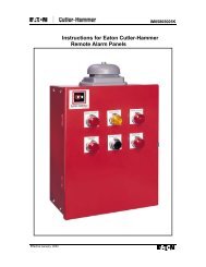
The basic function of the <strong>model</strong> FD4 Fire Pump Controller <strong>for</strong> diesel engine driven <strong>fire</strong> <strong>pump</strong>s is to automatically start the engine<br />
upon a drop in pressure in the water main, or from a number of other demand signals. This controller provides automatic cycled<br />
cranking, alarm and/or alarm shutdown protection <strong>for</strong> various engine failures. Stopping of the engine after the demand period is over<br />
may be either <strong>manual</strong> or automatic. This controller also includes an automatic weekly test starting feature.<br />
PART II: FUNCTIONS<br />
Equipment is provided in the Controller to provide the following functions:<br />
A. Automatic Starting From:<br />
a. Drop in water line pressure<br />
b. Loss of battery charger output (if enabled)<br />
c. Operation of optional remote start switches, such as remote start switch, deluge valve switch, <strong>fire</strong> alarm switch, etc.<br />
d. Weekly test timer<br />
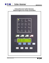
B. OID – Operator Interface Device - Provided <strong>for</strong> display of alarm functions, system pressure, battery volts, battery charger amps,<br />
alarm conditions, etc. Includes buttons <strong>for</strong> Auto, Test, Manual and Off. Also features a 4 line by 20 character LCD <strong>for</strong> display<br />
C. Automatic Cranking - A microprocessor controlled crank cycle timer provides six (6) fixed crank periods separated by five (5)<br />
rest periods each of approximately 15 seconds duration.<br />
D. Alarms and Signal Lights - Twelve (12) Standard lights are provided to give visual signals <strong>for</strong>; "System Fault”, "Battery #1<br />
Failure”, Battery #2 Failure", "Charger #1 Failure", Charger #2 Failure”, “AC Power Loss”, “Engine Running”,<br />
"Engine Failed to Start", "Engine Low Oil Pressure", "Engine High Water Temp", "Engine Overspeed" and “Low<br />
Fuel”. In addition the mode buttons have LED’s on the button indicating “Auto”, Manual”, “Test”, or “Off” mode. 12<br />
additional lights, configurable by the factory, are provided <strong>for</strong> "Pump Room Alarms". An audible alarm horn is mounted on<br />
the front of the cubicle <strong>for</strong> sounding in the event of failure. Terminals are provided <strong>for</strong> remote failure indication of the<br />
following:<br />
"Automatic Mode"<br />
"System Fault"<br />
"Engine Running (2 sets)"<br />
"Common Battery Fault"<br />
E. A data logger is provided as standard to record system pressure along with numerous alarm conditions and system events. The<br />
data can be displayed on the OID or can be downloaded to a PC through the RS232 port provided on the main system board or<br />
printed to the internal printer (if supplied).<br />
F. A weekly test timer is supplied to automatically start the engine any set day of the week, at a set time of day, and a preset run<br />
time. See System Config Screen 106.<br />
G. "Stop" Pushbutton - A pushbutton is provided to stop the engine in Automatic only after starting causes have returned to<br />
normal. This returns the controller to the automatic position.<br />
H. Integral Battery Chargers (Option J). There are two separate fully automatic, solid state chargers provided <strong>for</strong> maintaining full<br />
charge on the dual sets of engine batteries. An LED display is provided on the charger circuit board with a selector switch <strong>for</strong><br />
reading the charging current and voltage on each charger as standard.<br />
I. Cabinet - A heavy gauge steel cubicle encloses the controller. The OID, battery circuit breakers, and <strong>manual</strong> start pushbuttons<br />
are mounted behind a break-glass in the door of the cabinet.<br />
Page 3 of 25<br />
File Name: Doc#586C.doc
PART III: OPERATION OF THE CONTROLLER<br />
A. When the controller is the "Auto" mode and both circuit breakers are in the "On" position, the controller is in standby<br />
condition ready to start the engine automatically. A green pilot light above the "Auto" button will illuminate in this mode.<br />
Also, Battery #1 Fault and Battery #2 Fault lights should be off indicating that battery power is available.<br />
When the water pressure drops below a level which is set in System Config Screen 101, the Controller will actuate the starter<br />
motor and the cranking cycle will commence. If the engine starts and runs, cranking will cease and the protective circuits will be<br />
operative. If the engine fails to start after six (6) crank periods, cranking will cease, the "Engine Failed to Start" light will<br />
illuminate, and the alarm horn will sound. The battery alternating circuit alternates batteries on each crank attempt unless one<br />
battery is in a discharged state and incapable of cranking the engine. In this instance, the control will lock onto the other battery<br />
<strong>for</strong> the remaining cranking attempts. Dry contacts <strong>for</strong> remote indication of "Battery Failure/Missing Battery" are provided.<br />
The panel is wired so that optional remote start switches may be used, such as Deluge Valve, Remote Start pushbutton, Fire<br />
Alarm switches, etc. In addition, when “Power Failure Engine Startup” feature is enabled (System Config Screen 111), the<br />
Controller will automatically start the engine upon loss of Battery Charger output or AC Power loss, after an adjustable time<br />
delay (System Config Screen 112).<br />
While the engine is running, all protective circuits are operative. If the engine stops while running, and there is still an auto start<br />
demand, the control will attempt to restart the engine. If the engine fails to start the "Engine Failed to Start" light will<br />
illuminate and the alarm will sound. If, while the engine is operating, the oil pressure drops below a safe limit, the “Low Oil<br />
Pressure” light will illuminate immediately. After approximately seven (7) seconds the alarm will sound. Should the engine<br />
temperature exceed a safe limit while running, the “Engine High Water Temp.” light will illuminate and the alarm will sound<br />
indicating engine overheating.<br />
In case of Overspeed, the engine will be stopped and the "Engine Overspeed" light will illuminate and the alarm will sound.<br />
The light and alarm will stay on until the Engine Speed Switch and the Controller are <strong>manual</strong>ly reset. To <strong>manual</strong>ly reset the<br />
Controller, Press the “Off” button and the Press the "Reset" button on the OID <strong>for</strong> two seconds.<br />
The Controller may be configured as either "Manual" or "Automatic" stop as required (System Config Screen 104).<br />
"Manual" stop is set as standard. When Automatic stop is enabled the stop timer is preset at the factory to 30 minutes. Longer<br />
time settings can be set in System Config screen 105. When “Automatic Stop” is disabled, the engine will continue to run even<br />
though the pressure switch or other remote starting switch returns to its normal position. The engine can be stopped immediately<br />
only by pressing the stop button or by pressing the Off mode button. On engines that do not use the “energize to stop” method<br />
(i.e. Caterpillar), the engine may also be stopped by turning the circuit breakers BATT1 and BATT2 to OFF. If set up <strong>for</strong><br />
"Automatic" stop, the engine will be stopped automatically upon restoration to normal of whatever demand switch started the<br />
engine providing it has run at least 30 minutes or longer as set in System Config screen 105. If the demand period was less than<br />
the time set on the auto stop timer, the engine will continue to run until the timer times out and then will stop.<br />
B. When the "Test" mode button is pressed <strong>for</strong> two or more seconds, the engine will be started by causing a drop in water<br />
pressure. Failure alarm circuits will be operative in the "Test" mode. This method of starting provides a test of the Controller,<br />
thereby assuring proper operation when required. The engine will run <strong>for</strong> the time set in Auto Weekly Test Length Of Run Time<br />
(System Config Screen 109) or until the "Stop" push button is pressed or the “OFF” mode button is pressed.<br />
C. The "Manual" mode button is <strong>for</strong> <strong>manual</strong>ly starting the engine from either battery. The fuel and water solenoids are energized<br />
in this position, and the engine must be cranked by pushing one of the buttons located below the OID. "Manual Crank 1"<br />
cranks from Battery 1, and "Manual Crank 2" cranks from Battery 2. Pressing both buttons will result in cranking from both<br />
batteries simultaneously.<br />
D. When the engine is given a command to stop <strong>for</strong> any reason, terminal 12 will energize and will remain on <strong>for</strong> approximately 15<br />
seconds. The controller will not start until terminal 12 is de-energized again.<br />
E. Periodic Self Testing - The Test Run Timer can be set to give test runs on any day of the week and time of day desired. A<br />
timing element is incorporated in the control so that when the engine starts in this manner, it will run <strong>for</strong> a definite time be<strong>for</strong>e it<br />
shuts down. See System Config Screens 106 through 109 to set the starting time and length of engine running.<br />
F. Provision <strong>for</strong> sequential starting is accomplished by the use of adjustable time delay on pressure drop starting or “Deluge Valve”<br />
starting. On Multiple Pump installations these timers are set sequentially and progressively longer in time to prevent more than<br />
one (1) <strong>pump</strong> from starting simultaneously with another <strong>pump</strong>. Failure of the lead <strong>pump</strong> to start will not prevent subsequent<br />
<strong>pump</strong>s from starting. The time delay on starting is set in System Config Screen 103.<br />
Page 4 of 25<br />
File Name: Doc#586C.doc
PART IV: INSTALLATION AND TEST PROCEDURE<br />
A. INSTALLATION<br />
The Fire Pump Controller has been assembled and wired at the factory in accordance with the highest workmanship standards.<br />
All circuits and functions have been thoroughly tested to assure correct operation when properly installed. The installer should<br />
be completely familiar with the external hookup of the engine junction box to the terminal bar in the Controller. Various engine<br />
components must be wired to the proper terminal in the controller using the correct size of stranded wire. An appropriate size<br />
wire must be wired from the grounding lug in the controller to earth ground. In most cases, the engine manufacturer furnishes<br />
the engines with all accessories installed and wired to the connection box. There<strong>for</strong>e, it is only necessary to wire from the<br />
engine connection box to like numbered terminals in the Controller. Note proper wire sizes. All wires must be stranded.<br />
A drain valve is provided to relieve water pressure to the pressure switch, thus closing the pressure switch contacts and starting<br />
the engine. This test simulates an actual start demand. Since the Controller operates the drain valve only momentarily, a small<br />
amount of water is drained off. The water pressure sensing line to the Controller from the <strong>pump</strong> must be thoroughly flushed<br />
be<strong>for</strong>e connection to the Controller in order to remove chips, particles, or other matter, that could enter the plumbing<br />
components in the Controller.<br />
Controllers configured with "Automatic Stop" enabled may be changed to "Manual" stop by disabling this feature in System<br />
Config Screen 104. If deluge valve switches are to be used <strong>for</strong> starting, enable the Deluge Valve Option in Config Screen 121<br />
and connect the remote normally closed switch to terminals 31 and 111.<br />
B. TEST PROCEDURE<br />
All of the following tests should be made on each unit after installation. If each test is satisfactory, the operator may place the<br />
control switch in "Auto" mode and depend upon the panel operating properly when required. Also, any one or all of these tests<br />
may be carried out at any time after installation, if so desired. NOTE: If 115 Volts A.C. is not connected to<br />
Controller, the "Charger Failure" lights and “AC Power Loss” light and alarm will be activated and if the Power<br />
Failure Start feature (System Config Screen 111) is enabled, the controller will start automatically. The 115VAC must be<br />
turned on to prevent the engine from starting.<br />
ENGINE TERMINAL (terminals 1-12) STATUS INDICATOR LIGHTS<br />
Light Emitting Diodes (L.E.D.) lights have been installed on the microprocessor module to indicate the status of each engine<br />
terminal. Status indication is given below:<br />
Terminal Number<br />
L.E.D. (light) "ON" Indication<br />
(Microprocessor Func #)<br />
1 (Out 06) Power available to fuel and water solenoids<br />
2 (In 06) Speed switch has operated into engine running mode<br />
3 (In 07) Speed switch has operated into overspeed mode<br />
4 (In 08) Oil Pressure switch contacts closed (Low Oil Pressure)<br />
5 (In 09) Water temperature switch contacts closed (High Engine Temp.)<br />
6 (Ain 02) Battery #1 voltage present<br />
8 (Ain 03) Battery #2 voltage present<br />
9 (Out 02) Crank #1 voltage present (while cranking on Battery #1)<br />
10 (Out 03) Crank #2 voltage present (while cranking on Battery #2)<br />
12 (Out 07) Energize to stop voltage present<br />
a. BATTERY LOCKOUT TEST:<br />
1. Turn on Battery #1 switch and Battery #2 switch.<br />
2. Press the "Reset" button. Battery #1 and Battery #2 Failure lights should be off.<br />
3. Turn Battery #1 switch off <strong>for</strong> a couple of seconds and back on. Battery #1 light should go off and remain off.<br />
4. Press "Reset" button. Battery #1 light should come on.<br />
5. Repeat <strong>for</strong> Battery #2.<br />
b. CRANKING CYCLE TEST: This test simulates a condition where the engine refuses to start.<br />
1. Disconnect Terminal No.1 on Controller panel. NOTE: Disconnecting Terminal No.1 is <strong>for</strong> the purpose of<br />
removing power from the fuel solenoid so engine will not start. On engines where the fuel solenoid is not used<br />
Page 5 of 25<br />
File Name: Doc#586C.doc
(Caterpillar), or is connected other than through Terminal #1 (Clarke-G.M.), other means must be used to<br />
stop fuel flow to the engine to prevent starting.<br />
2. Press the "Test" mode button to start cranking the engine. Time the crank and rest periods, and count the number of<br />
cranks. There should be six (6) crank periods separated by five (5) rest periods each of approximately 15-seconds<br />
duration. The "Failed to Start" light should come on and the alarm horn should sound. Status indicator light <strong>for</strong><br />
Terminal #1 should come on as soon as the "Test" push button is pressed and the pressure drops below the low set<br />
point. Indicator lights <strong>for</strong> terminals 9 and 10 should come on alternately to indicate cranking cycle. (See above)<br />
3. Press the "Stop" push button to stop the engine and properly reconnect all leads.<br />
NOTE: In order to prevent discharging the starting batteries, this same test can be made without actually<br />
cranking the engine by disconnecting the starter cable and observing the action of the starter contactors<br />
and/or status indicator lights <strong>for</strong> terminals 9 and 10.<br />
c. CHECKING STARTING MOTOR RELEASE<br />
1. Press the “Test” mode button. Engine should start promptly and starting motor should release at approximately 1/3 of<br />
engine speed. Status indicator light <strong>for</strong> terminal #2 should come on to indicate speed switch has operated to disconnect<br />
cranking and the Engine Running LED should illuminate.<br />
NOTE: A convenient method of determining the exact instant the starter releases is to connect a battery test light or<br />
voltmeter across the starter terminals and observe when power is disconnected.<br />
2. Press the “Stop” push button to stop the engine.<br />
d. OIL PRESSURE FAILURE TEST:<br />
1. Press the "Test" mode button to start engine. When the engine is starting and oil pressure is not yet up to full pressure,<br />
the "Engine Low Oil Pressure" light will illuminate, but the horn will not sound. When pressure builds up, and the<br />
switch opens, the light will go out. This feature provides indication that the oil pressure switch contacts are operating<br />
in a normal manner.<br />
2. After the engine is running, connect a temporary jumper between terminal #4 and terminal #11.<br />
3. Both the "Engine Low Oil Pressure" light and status indicator light <strong>for</strong> terminal #4 should come on immediately.<br />
Wait approximately seven (7) seconds. Alarm horn should sound.<br />
4. Press the "Stop" push button to stop the engine and remove jumper between terminal #4 and terminal #11.<br />
5. Wait at least 30 seconds <strong>for</strong> elements to reset be<strong>for</strong>e making any further tests.<br />
e. WATER TEMPERATURE FAILURE TEST:<br />
1. Press the "Test" push button to start engine.<br />
2. Jumper contacts on water temperature switch on engine.<br />
3. Alarm horn sounds and the "High Water Temperature" light on controller illuminates immediately. Status indicator<br />
light <strong>for</strong> terminal #5 should come on with "High Water Temperature” light.<br />
4. Press the "Stop" push button to stop the engine and remove jumper on water switch.<br />
f. OVERSPEED FAILURE TEST:<br />
1. Press the "Test" mode button to start engine.<br />
2. Momentarily short the contacts on the engine speed switch, or connect a temporary jumper between terminal #3 and #6<br />
on the controller.<br />
3. The alarm horn sounds and the "Engine Overspeed" light will illuminate immediately. Engine comes to a stop.<br />
Status indicator lights <strong>for</strong> terminals #3 and #12 should come on with the "Engine Overspeed" light.<br />
4. Press the "Reset" button to reset the “Overspeed” alarm.<br />
g. AUTOMATIC STARTING TESTS:<br />
1. Place control in "Auto" position.<br />
2. Bleed off pressure in system until pressure drops below the low set point.<br />
Page 6 of 25<br />
File Name: Doc#586C.doc
3. Engine should start automatically and continue to run after pressure rises above the high set point, if arranged <strong>for</strong><br />
"Manual" stop. If arranged <strong>for</strong> "Automatic" stop, engine will continue to run <strong>for</strong> time set on Engine Run Timer and<br />
then stop.<br />
4. Press the "Stop" push button to stop the engine.<br />
5. Repeat tests <strong>for</strong> each demand switch such as deluge valve, remote start, etc.<br />
h. PERIODIC WEEKLY START TEST:<br />
1. Pressure must be up and all other demand switches de-activated.<br />
2. 115 V.A.C. power must be turned on to the panel.<br />
3. When the current day and time of day matches the settings in System Config screens 107 and 108, the solenoid drain<br />
valve will energize and the engine will begin cranking. It will continue to run <strong>for</strong> the amount of time set<br />
i. SETTING PROGRAM WEEKLY TEST TIME: System Config screen 106 through 109.<br />
j. REMOTE START SWITCH CIRCUITS: Field wiring terminals are provided on the controller so that optional remote<br />
start switches such as Remote Pushbutton Stations, Deluge Valve Switch, Fire Alarm Switches, etc., may be used to start<br />
the engine. Two (2) sets of terminals are provided. Terminals #112 and #31 are used <strong>for</strong> remote <strong>manual</strong> start push buttons<br />
(close to start). Terminals #111 and #31 are used <strong>for</strong> remote Deluge Valve Switch or other remote automatic start switches<br />
(open to start). Upon automatic start from this type of switch, the engine will be stopped either automatically (if set <strong>for</strong><br />
automatic stop) after the demand switch de-activates and Engine Auto Stop Timer times out, or <strong>manual</strong>ly at the Controller.<br />
Terminals #111 and #31 must have a jumper installed if a remote Deluge switch is “Enabled” but not to be used. When the<br />
controller is shipped from the factory Deluge Valve start is Disabled (System Config screen 121).<br />
k. AC POWER FAILURE STARTING: If this feature has been enabled it can be tested by disconnecting the normal 115<br />
V.A.C. to the Controller. After the preset time delay (which is specified in System Config screen 112), the Controller will<br />
commence cranking the engine. The "Charger #1 Failure”, “Charger #2 Failure”, and “AC Power Loss" lamps will<br />
illuminate and the alarm will sound without delay.<br />
l. NORMAL OPERATION – AUTOMATIC: Press "Auto" mode button on OID. A green "Automatic Mode" light will<br />
illuminate and the engine will automatically start upon drop in pressure or operation of other start switches. If the Auto<br />
Stop Timer is disabled (Manual Stop) the engine must be turned off at the Controller. When the Auto Stop Timer is<br />
enabled, upon termination of the demand signal, the engine will run <strong>for</strong> the length of time left on the Auto Stop Timer and<br />
then will stop automatically.<br />
m. AN ADJUSTABLE SEQUENTIAL START TIMER IS SUPPLIED FOR MULTIPLE PUMP INSTALLATION:<br />
Normally, the leading <strong>pump</strong> Controller will not have a delay timer and will commence cranking the engine immediately<br />
upon operation of a demand signal (other than Power Failure which is time delayed). The subsequent Controllers will have<br />
a time delay which is adjustable from 0 to 999 seconds. Each time delay should be set with progressively longer times on<br />
each subsequent <strong>pump</strong>. The recommended time interval is ten (10) to fifteen (15) seconds. This may be extended or<br />
shortened as required by the local authorities having jurisdiction.<br />
n. PUMP ROOM ALARMS: Field terminals may be provided <strong>for</strong> various inputs from <strong>pump</strong> room alarms. These alarms<br />
include: Low Fuel, Low Pump Room Temperature, Reservoir Low, Reservoir Empty, Low Suction Pressure, Relief Valve<br />
Discharge and/or Flow Meter On etc. A maximum of twelve (12) <strong>pump</strong> room alarms is available. The Controller is<br />
arranged so that the alarm horn will sound and the light will come on when the alarm sensor contacts close. These <strong>pump</strong><br />
room alarms can be silenced with the “Silence” push button on the OID if they have been configured as silenceable.<br />
Page 7 of 25<br />
File Name: Doc#586C.doc
PART V: ADDITIONAL OPTIONAL FEATURES<br />
A. Battery Charger Operation: The Battery Chargers are mounted in the engine controller, and are factory wired to the controller<br />
terminal block from which it obtains its 120 volt, 50-60 Hz. supply voltage, and through which it provides charging current to<br />
the batteries. The charging current to the two (2) batteries and the battery voltage is monitored by the controller and displayed<br />
on the OID. The charger output is current limited and provides full protection during the engine cranking cycle. The charger<br />
input and output are fused <strong>for</strong> protection in case of a failure of the control circuit or other internal component.<br />
Each battery charger is fully automatic, and will charge the batteries at a rate of up to 10 amperes. As the batteries approach full<br />
charge, the current will taper off to a predetermined level at which time the charger automatically switches to the float mode of<br />
operation. In the float mode the charger maintains the batteries at the float potential (approximately 12.7 volts <strong>for</strong> a 12-volt<br />
battery or 25.4 volts <strong>for</strong> the 24-volt battery).<br />
The charger provides a means of monitoring the charger output to sound an alarm in case of loss of charger output. This also<br />
provides a means of monitoring the A.C. power since a loss of A.C. power results in a loss of charger output.<br />
In the event that a battery is lost or disconnected the output of the charger will stop (0 volts). This will allow the voltage sensing<br />
circuit of the <strong>fire</strong> <strong>pump</strong> controller microprocessor to detect a missing battery or open circuit from the battery. This will result in<br />
the respective Battery Fault light to illuminate and the alarm horn to sound. The battery must be connected to the controller to<br />
reset the alarm.<br />
Generally, when all conditions are normal, the batteries will come to a full charge prior to the 24 hour period. As batteries begin<br />
to charge, the controller OID will indicate a gradual decrease in current flow. When these ammeters indicate a current level of<br />
less than 0.5 amps the charger will be in a trickle mode.<br />
Check batteries daily <strong>for</strong> a few days after initial installation has been made, and weekly thereafter. Batteries should be checked<br />
<strong>for</strong> overcharging (gassing), or undercharging (low voltage, or low specific gravity of the electrolyte or acid.<br />
CAUTION: Under no circumstances should new electrolyte (acid) be added to a battery that has been previously filled.<br />
Only distilled water is recommended <strong>for</strong> maintenance purposes.<br />
Page 8 of 25<br />
File Name: Doc#586C.doc
PART VI: OPERATOR INTERFACE DEVICE (OID) USE AND NAVIGATION<br />
The Operator Interface Device (OID) provides visual indication of the alarms, status of system parameters, and an interface to<br />
change set points to configure the FD4 to operate appropriately <strong>for</strong> various installation requirements.<br />
Labeled LED<br />
Annunciator<br />
Common Tasks Per<strong>for</strong>med Using The OID<br />
Silencing Horn: If a horn is sounding and the alarm is silence<br />
able, a quick press of the [SILENCE/RESET/ESC] will silence the<br />
horn (less than 1 second press).<br />
Resetting Alarms: If the alarm condition has cleared, press and<br />
hold the [SILENCE/RESET/ESC] button 2 to 5 seconds to reset<br />
alarms. “Engine Failed to Start” and “Engine Overspeed” alarms<br />
require the system to be in the OFF mode be<strong>for</strong>e a reset is allowed.<br />
Operating Mode Change: The operational mode that the<br />
controller is in can be changed by pressing the [AUTO]<br />
[MANUAL] or [OFF] buttons. An LED will illuminate on the<br />
appropriate button indicating the mode of operation the controller<br />
is in.<br />
Test Mode: When controller is in Auto Mode, pressing and<br />
holding the [TEST] button <strong>for</strong> two or more seconds will open the<br />
pressure drain solenoid thus dropping the pressure which causes<br />
the controller to start the engine. Pressing and releasing the<br />
[TEST] button in Manual Mode directly controls the opening and<br />
closing of the drain solenoid. The engine will not automatically<br />
start when in Manual Mode.<br />
Lamp Test: To illuminate and check all the OID LED’s and the<br />
horn, press and hold the [SILENCE/RESET/ESC] button 5 or more<br />
seconds or until all the lights turn on.<br />
System Operation and<br />
Control Type Buttons<br />
Digital Display With<br />
Navigation Buttons<br />
Page 9 of 25<br />
File Name: Doc#586C.doc
OID Screen Map<br />
METRON OID100<br />
POWER<br />
1<br />
2<br />
3<br />
SYSTEM<br />
STATUS<br />
SYSTEM<br />
LOGS<br />
CONFIG<br />
PRINT<br />
CHANGE/<br />
ENTER<br />
AUTO MANUAL TEST<br />
OFF<br />
SILENCE/<br />
RESET/<br />
ESC<br />
1 SYSTEM STATUS B1<br />
PRES STRT BAT1 BAT2<br />
110 100 13V 13V<br />
psi psi 6A 0A<br />
SYSTEM LOGS<br />
1) Alarm Log<br />
2) Event Log<br />
3) Pressure Log<br />
1 CONFIG<br />
1) SYSTEM SETPOINTS<br />
2) USER PREFERENCES<br />
3) TECH SCREENS<br />
2 SYSTEM STATUS<br />
Engine Countdown Tmr<br />
0sec Until Start<br />
0min Until Stop<br />
2 CONFIG<br />
1) ANALOG SIGNALS<br />
2) AUXILLIARY ALARMS<br />
3 SYSTEM STATUS<br />
Engine Countdown Tmr<br />
For AC Power Outage<br />
0min Until Start<br />
4 SYSTEM STATUS<br />
Engine Hrs: 5.3<br />
# Of Starts: 8<br />
Mon02/17/03 17:53:26<br />
5 SYSTEM STATUS<br />
Firmware Ver SV 1.1<br />
Commissioned Date:<br />
11/15/02<br />
# 1 ALARM LOG<br />
Engine Failed To<br />
Start Alarm Occurred<br />
02/16/03 07:32:15<br />
# 1 ALARM DETAILS<br />
Engine Failed To<br />
Start Alarm Occurred<br />
02/16/03 07:32:15<br />
# 1 ALARM DETAILS<br />
Pressure: 83.2psi<br />
System Auto:Yes<br />
Engine Running:No<br />
# 1 EVENT LOG<br />
System in Off<br />
Mode Occurred<br />
02/16/03 13:15:15<br />
# 1 EVENT DETAILS<br />
System in Off<br />
Mode Occurred<br />
02/16/03 13:15:15<br />
# 1 EVENT DETAILS<br />
Pressure: 83.2psi<br />
System Auto:Yes<br />
Engine Running:No<br />
PRESSURE LOG<br />
02/16/03 17:52:45<br />
112 psi<br />
Skip Rate:[EACH ]<br />
PRESSURE LOG<br />
02/16/03 17:52:30<br />
112 psi<br />
Skip Rate:[EACH ]<br />
PRESSURE LOG<br />
02/16/03 17:52:15<br />
113 psi<br />
Skip Rate:[EACH ]<br />
Continued on next<br />
page.<br />
# 1 ALARM DETAILS<br />
Charger #1 OK:No<br />
Charger #2 OK:Yes<br />
Battery #1 OK:No<br />
# 1 ALARM DETAILS<br />
Battery #2 OK:Yes<br />
AC Power Avail:Yes<br />
Low fuel level:No<br />
# 1 EVENT DETAILS<br />
Charger #1 OK:Yes<br />
Charger #2 OK:Yes<br />
Battery #1 OK:Yes<br />
# 1 EVENT DETAILS<br />
Battery #2 OK:Yes<br />
AC Power Avail:Yes<br />
Low Fuel Level:No<br />
| |<br />
| |<br />
| |<br />
# 2 ALARM LOG<br />
AC Power Failure<br />
Alarm Cleared<br />
02/16/03 07:09:48<br />
# 2 EVENT LOG<br />
Engine Failed To<br />
Start Alarm Occurred<br />
02/16/03 07:32:15<br />
# 3 ALARM LOG<br />
AC Power Failure<br />
Alarm Occurred<br />
02/16/03 06:49:03<br />
# 3 EVENT LOG<br />
AC Power Failure<br />
Alarm Cleared<br />
02/16/03 07:09:48<br />
| |<br />
| |<br />
| |<br />
| |<br />
| |<br />
| |<br />
Page 10 of 25<br />
File Name: Doc#586C.doc
OID Screen Map (continued)<br />
1 CONFIG<br />
1) SYSTEM SETPOINTS<br />
2) USER PREFERENCES<br />
3) TECH SCREENS<br />
2 CONFIG<br />
1) ANALOG SIGNALS<br />
2) AUXILLIARY ALARMS<br />
101 SYSTEM SETPOINTS<br />
Engine Start<br />
Pressure<br />
[100.0]psi 0-999.9<br />
201 USER PREFERENCES<br />
Set System Real<br />
Time Clock<br />
[17:03:52]<br />
301 TECH SCREENS<br />
SPECIAL: Engine<br />
Minimum Run Time<br />
[No ]<br />
400 ANALOG SIGNALS<br />
Analog Input 01<br />
Slope:<br />
[0.2135677]<br />
501 AUX USER PROGRAM<br />
AUX# 1<br />
Enabled<br />
[Yes]<br />
102 SYSTEM SETPOINTS<br />
Engine Stop<br />
Pressure<br />
[110.0]psi 0-999.9<br />
202 USER PREFERENCES<br />
Set System Date<br />
[02/16/03]<br />
302 TECH SCREENS<br />
SPECIAL: Engine<br />
Minimum Run Time<br />
[15]minutes 1-99<br />
401 ANALOG SIGNALS<br />
Analog Input 01<br />
Offset:<br />
[- 75.6030]<br />
502 AUX USER PROGRAM<br />
AUX# 1<br />
Input Number<br />
[30] 0-53<br />
103 SYSTEM SETPOINTS<br />
Engine Start Delay<br />
Time<br />
[ 10] seconds 1-999<br />
203 USER PREFERENCES<br />
Set System Day<br />
Of The Week<br />
[Sun]<br />
303 TECH SCREENS<br />
Energized To Stop<br />
Fuel Solenoid Time<br />
[10]seconds 0-99<br />
402 ANALOG SIGNALS<br />
Analog Input 1 651<br />
Minimum Counts<br />
[ 200]<br />
503 AUX USER PROGRAM<br />
AUX# 1<br />
Input Contact Type<br />
[NO ]<br />
104 SYSTEM SETPOINTS<br />
Engine Automatic<br />
Stop Enabled<br />
[Yes]<br />
204 USER PREFERENCES<br />
Log System Pressure<br />
Drop Events<br />
[Yes]<br />
304 TECH SCREENS<br />
Low Oil Pressure<br />
Alarm Delay Time<br />
[ 7]seconds 1-99<br />
410 ANALOG SIGNALS<br />
Analog Input 02<br />
Slope:<br />
[0.0105451]<br />
504 AUX USER PROGRAM<br />
AUX# 1<br />
Trip Time<br />
[ 0]sec 0-999<br />
105 SYSTEM SETPOINTS<br />
Engine Minimum<br />
Run Time<br />
[30]minutes 30-99<br />
205 USER PREFERENCES<br />
Low Pressure Event<br />
Trip Pressure<br />
[ 60.0]psi 0-999.9<br />
305 TECH SCREENS<br />
Nominal Battery<br />
Voltage<br />
[12]VDC 10-99<br />
411 ANALOG SIGNALS<br />
Analog Input 02<br />
Offset:<br />
[ 1.7079]<br />
505 AUX USER PROGRAM<br />
AUX# 1<br />
Reset Time<br />
[ 0]sec 0-999<br />
106 SYSTEM SETPOINTS<br />
Automatic Weekly<br />
Engine Test Run<br />
[Yes]<br />
206 USER PREFERENCES<br />
Low Pressure Event<br />
Reset Time<br />
[15] seconds 0-20<br />
306 TECH SCREENS<br />
Battery Low Voltage<br />
Alarm Trip Voltage<br />
[ 9.0]VDC 8-99<br />
412 ANALOG SIGNALS<br />
Analog Input 2 1174<br />
Minimum Counts<br />
[ 0]<br />
506 AUX USER PROGRAM<br />
AUX# 1<br />
Auto Reset Enabled<br />
[Yes]<br />
107 SYSTEM SETPOINTS<br />
Auto Weekly Engine<br />
Test Day Of The Week<br />
[Mon]<br />
207 USER PREFERENCES<br />
Time Between<br />
Pressure Log Samples<br />
[ 15] seconds 15-999<br />
307 TECH SCREENS<br />
Battery Low Voltage<br />
Alarm Trip Time<br />
[ 5]seconds 0-99<br />
420 ANALOG SIGNALS<br />
Analog Input 03<br />
Slope:<br />
[0.0105451]<br />
507 AUX USER PROGRAM<br />
AUX# 1<br />
Horn Enabled<br />
[No ]<br />
108 SYSTEM SETPOINTS<br />
Auto Weekly Engine<br />
Test Start Time<br />
[10:00:00]<br />
208 USER PREFERENCES<br />
Auto Print Each<br />
Pressure Log Sample<br />
[No ]<br />
308 TECH SCREENS<br />
Change Tech Password<br />
[******]<br />
421 ANALOG SIGNALS<br />
Analog Input 03<br />
Offset:<br />
[ 1.7079]<br />
508 AUX USER PROGRAM<br />
AUX# 1<br />
Horn Silence<br />
[No ]<br />
109 SYSTEM SETPOINTS<br />
Auto Weekly Test<br />
Length Of Run Time<br />
[30] minutes 30-99<br />
110 SYSTEM SETPOINTS<br />
Auto Weekly Test<br />
Oil/Water Shutdown<br />
[No]<br />
209 USER PREFERENCES<br />
Auto Print Each<br />
Event Log Entry<br />
[No ]<br />
210 USER PREFERENCES<br />
Selective Range<br />
Printing<br />
[ 1] Be<strong>for</strong>e 1-99<br />
309 TECH SCREENS<br />
Password Logout<br />
Time<br />
[ 5] minutes 1-15<br />
310 TECH SCREENS<br />
System Commissioned<br />
Date<br />
[00/00/00]<br />
422 ANALOG SIGNALS<br />
Analog Input 3 1225<br />
Minimum Counts<br />
[ 0]<br />
ANALOG INPUT COUNTS<br />
649 1176 1221 0<br />
0 0 0 0<br />
0 0<br />
509 AUX USER PROGRAM<br />
AUX# 1<br />
LED Number<br />
[ 0] 0-24<br />
510 AUX USER PROGRAM<br />
AUX# 1<br />
Output1 Number<br />
[ 0] 0-24<br />
111 SYSTEM SETPOINTS<br />
Power Failure Engine<br />
Startup<br />
[No]<br />
211 USER PREFERENCES<br />
Selective Range<br />
Printing<br />
[ 1] After 1-99<br />
311 TECH SCREENS<br />
Expiration Time<br />
For Test Settings<br />
[ 5]minutes 1-60<br />
511 AUX USER PROGRAM<br />
AUX# 1<br />
Output2 Number<br />
[ 0] 0-24<br />
112 SYSTEM SETPOINTS<br />
Power Failure Engine<br />
Start Delay Time<br />
[ 60] minutes 0-500<br />
212 USER PREFERENCES<br />
LCD Back Light Mode<br />
0=Always on<br />
[0]] 1=Power Save<br />
312 TECH SCREENS<br />
STARTUP TEST: Test<br />
Settings Enabled<br />
[No ]<br />
512 AUX USER PROGRAM<br />
AUX# 1<br />
Output3 Number<br />
[ 0] 0-24<br />
113 SYSTEM SETPOINTS<br />
Pressure Transducer<br />
Failure Engine Start<br />
[Yes]<br />
213 USER PREFERENCES<br />
Language Select<br />
[English]<br />
313 TECH SCREENS<br />
STARTUP TEST: Engine<br />
Minimum Run Time<br />
[15]minutes 1-99<br />
513 AUX USER PROGRAM<br />
AUX# 1<br />
Record In Event Log<br />
[No ]<br />
114 SYSTEM SETPOINTS<br />
Surge Control Valve<br />
Open/Close Control<br />
[No ]<br />
214 USER PREFERENCES<br />
Change User Password<br />
Level 1<br />
[****]<br />
314 TECH SCREENS<br />
FACTORY TEST: Test<br />
Settings Enabled<br />
[No ]<br />
514 AUX USER PROGRAM<br />
AUX# 1<br />
Record In Alarm Log<br />
[No ]<br />
115 SYSTEM SETPOINTS<br />
Surge Control Valve<br />
Delay Time<br />
[ 15] seconds 0-999<br />
315 TECH SCREENS<br />
FACTORY TEST: Engine<br />
Crank Time<br />
[15]seconds 1-15<br />
515 AUX USER PROGRAM<br />
AUX# 1<br />
Text Message Number<br />
[ 0] 0-27<br />
116 SYSTEM SETPOINTS<br />
Shutdown On Low<br />
Intake Pressure/Lvl<br />
[No ]<br />
316 TECH SCREENS<br />
FACTORY TEST: Engine<br />
Crank Rest Time<br />
[15]seconds 1-15<br />
117 SYSTEM SETPOINTS<br />
Shutdown On Low<br />
Intake Trip Time<br />
[ 20]seconds 0-999<br />
118 SYSTEM SETPOINTS<br />
Low Intake Shutdown<br />
Auto Reset<br />
[Yes]<br />
317 TECH SCREENS<br />
Alarm Log 1/10<br />
Event Log 1/1569<br />
Pr. Log 1/25123<br />
119 SYSTEM SETPOINTS<br />
Low Intake Shutdown<br />
Auto Reset Time<br />
[ 20]seconds 0-999<br />
120 SYSTEM SETPOINTS<br />
Pressure Switch<br />
Engine Start<br />
[No ]<br />
121 SYSTEM SETPOINTS<br />
Deluge Valve<br />
Engine Start<br />
[Yes]<br />
122 SYSTEM SETPOINTS<br />
High System Pressure<br />
Alarm<br />
[100.0]psi 0-999.9<br />
Page 11 of 25<br />
File Name: Doc#586C.doc
The [SYSTEM STATUS], [SYSTEM LOGS], and [CONFIG] buttons navigate the user to the top screen of a column of similarly<br />
grouped screens or menus.<br />
SYSTEM STATUS: The [SYSTEM STATUS] button can be pressed at any time to return the screen to the home System Status<br />
screen #1. System Status screens display the real time in<strong>for</strong>mation variables about the <strong>pump</strong> system.<br />
SYSTEM LOGS: The [SYSTEM LOGS] button displays the System Logs menu. Once the menu is displayed, buttons with<br />
numbers on them can be used to enter the selected data log. See the following page <strong>for</strong> details on navigating the System<br />
Logs.<br />
CONFIGURATION: The [CONFIG] button displays the Config menu which groups the different types of set points that<br />
configure the system to operate in the desired manner. Use the [UP] and [DOWN] buttons to scroll between the two menu<br />
screens. Buttons with numbers on them can be used to enter the selected configuration screen group. See the Configuring<br />
the FD4 section <strong>for</strong> descriptions on the functionality of each set point.<br />
1 SYSTEM STATUS B1<br />
PRES STRT BAT1 BAT2<br />
110 100 13V 13V<br />
psi psi 6A 0A<br />
2 SYSTEM STATUS<br />
Engine Countdown Tmr<br />
0sec Until Start<br />
0min Until Stop<br />
3 SYSTEM STATUS<br />
Engine Countdown Tmr<br />
For AC Power Outage<br />
0min Until Start<br />
4 SYSTEM STATUS<br />
Engine Hrs: 5.3<br />
# Of Starts: 8<br />
Mon02/17/03 17:53:26<br />
5 SYSTEM STATUS<br />
Firmware Ver SV 1.1<br />
Commissioned Date:<br />
11/15/02<br />
SYSTEM LOGS<br />
1) Alarm Log<br />
2) Event Log<br />
3) Pressure Log<br />
# 1 ALARM LOG<br />
Engine Failed To<br />
Start Alarm Occurred<br />
02/16/03 07:32:15<br />
# 1 EVENT LOG<br />
System in Off<br />
Mode Occurred<br />
02/16/03 13:15:15<br />
PRESSURE LOG<br />
02/16/03 17:52:45<br />
112 psi<br />
Skip Rate:[EACH ]<br />
See the following page <strong>for</strong> an example of<br />
scrolling through the Alarm, Event, and<br />
Pressure Logs<br />
1 CONFIG<br />
1) SYSTEM SETPOINTS<br />
2) USER PREFERENCES<br />
3) TECH SCREENS<br />
2 CONFIG<br />
1) ANALOG SIGNALS<br />
2) AUXILLIARY ALARMS<br />
3) COMM PORTS<br />
101 SYSTEM SETPOINTS<br />
Engine Start<br />
Pressure<br />
[100.0]psi 0-999.9<br />
201 USER PREFERENCES<br />
Set System Real<br />
Time Clock<br />
[17:03:52]<br />
301 TECH SCREENS<br />
SPECIAL: Engine<br />
Minimum Run Time<br />
[Yes]<br />
401 ANALOG SIGNALS<br />
Analog Input 01<br />
Slope:<br />
[0.21346771]<br />
501 AUX USER PROGRAMS<br />
AUX# 1<br />
Enabled<br />
[Yes]<br />
Page 12 of 25<br />
File Name: Doc#586C.doc
SYSTEM LOGS: The FD4 has three separate data logs; 1) alarm log, 2) event log, and 3) pressure log. The alarm log is a<br />
subset of the event log and only displays the last ten alarms that have occurred or cleared. The event log records all alarm and<br />
system function type events<br />
SYSTEM LOGS<br />
1) Alarm Log<br />
2) Event Log<br />
3) Pressure Log<br />
SYSTEM LOGS: The [UP] and [DOWN] arrow buttons can be used to scroll through the<br />
three data logs. The [CHANGE/ENTER] button enters and exits the alarm/event details in<br />
either the Alarm or Event logs. In the Pressure Log the [CHANGE/ENTER] button changes<br />
the skip rate used to scroll through the logged pressure readings.<br />
# 1 ALARM LOG<br />
Engine Failed To<br />
Start Alarm Occurred<br />
02/16/03 07:32:15<br />
# 1 ALARM DETAILS<br />
Engine Failed To<br />
Start Alarm Occurred<br />
02/16/03 07:32:15<br />
# 1 ALARM DETAILS<br />
Pressure: 83.2psi<br />
System Auto:Yes<br />
Engine Running:No<br />
# 1 ALARM DETAILS<br />
Charger #1 OK:No<br />
Charger #2 OK:Yes<br />
Battery #1 OK:No<br />
# 1 ALARM DETAILS<br />
Battery #2 OK:Yes<br />
AC Power Avail:Yes<br />
Low fuel level:NO<br />
# 2 ALARM LOG<br />
AC Power Failure<br />
Alarm Cleared<br />
02/16/03 07:09:48<br />
# 3 ALARM LOG<br />
AC Power Failure<br />
Alarm Occurred<br />
02/16/03 06:49:03<br />
# 1 EVENT LOG<br />
System in Off<br />
Mode Occurred<br />
02/16/03 13:15:15<br />
# 1 EVENT DETAILS<br />
System in Off<br />
Mode Occurred<br />
02/16/03 13:15:15<br />
# 1 EVENT DETAILS<br />
Pressure: 83.2psi<br />
System Auto:Yes<br />
Engine Running:No<br />
# 1 EVENT DETAILS<br />
Charger #1 OK:Yes<br />
Charger #2 OK:Yes<br />
Battery #1 OK:Yes<br />
# 1 EVENT DETAILS<br />
Battery #2 OK:Yes<br />
AC Power Avail:Yes<br />
Low Fuel Level:NO<br />
# 2 EVENT LOG<br />
Engine Failed To<br />
Start Alarm Occurred<br />
02/16/03 07:32:15<br />
# 3 EVENT LOG<br />
AC Power Failure<br />
Alarm Cleared<br />
02/16/03 07:09:48<br />
PRESSURE LOG<br />
02/16/03 17:52:45<br />
112 psi<br />
Skip Rate:[EACH ]<br />
PRESSURE LOG<br />
02/16/03 17:52:30<br />
112 psi<br />
Skip Rate:[EACH ]<br />
PRESSURE LOG<br />
02/16/03 17:52:15<br />
113 psi<br />
Skip Rate:[EACH ]<br />
Page 13 of 25<br />
File Name: Doc#586C.doc
Printing System Log Data: The following applies if a printer has been installed or a PC is connected to the RS232 com ports<br />
using a null modem cable. When the [PRINT] button is pressed when looking at data in one of the three logs, a menu <strong>for</strong> what is<br />
to be printed is displayed. Pressing [1] prints just the alarm/event/pressure reading currently being displayed. Pressing [2] prints<br />
a range of data be<strong>for</strong>e and after the currently displayed alarm/event/pressure reading currently displayed. The range can be<br />
changed in the User Preferences setpoints 210 and 211. To download the Log Data using the USB port, log onto Metron’s web<br />
site at www.metroninc.com and click on the Fire Pump Controller link. Then click on the “Click Here to Download Metron’s<br />
USB application” link. Install this onto your PC. If you use the RS232 port to download the data, use Microsoft windows<br />
Hyperlink program and configure <strong>for</strong> Baud Rate as 9600, Data bits as 8, Parity as None, Stop Bits as 1 and Flow Control as None.<br />
When the print button on the OID is pressed, data will be sent to the PC via the port you have connected to.<br />
#1 EVENT LOG<br />
AC Power Restored<br />
Occurred On<br />
11/16/02 07:32:15<br />
#1 EVENT LOG<br />
AC Power Restored<br />
Occurred On<br />
11/16/02 07:32:15<br />
#1 EVENT DETAILS<br />
AC Power Restored<br />
Occurred On<br />
11/16/02 07:32:15<br />
#1 EVENT DETAILS<br />
Pressure:360psi<br />
System Auto:Yes<br />
Engine Running:No<br />
#1 EVENT DETAILS<br />
Charger #1 OK:Yes<br />
Charger #2 OK:Yes<br />
Battery #1 OK:Yes<br />
#1 EVENT DETAILS<br />
Battery #2 OK:Yes<br />
AC Power Avail:Yes<br />
Fuel Level OK:Yes<br />
PRESSURE LOG<br />
01/01/03 17:52:45<br />
600 psi<br />
Skip Rate:[EACH ]<br />
PRINT OPTIONS<br />
1) PRINT THIS EVENT<br />
2) PRINT EVENT RANGE<br />
10 BEFORE,10 AFTER<br />
PRINT OPTIONS<br />
1) PRINT THIS EVENT<br />
2) PRINT EVENT RANGE<br />
10 BEFORE,10 AFTER<br />
PRINT OPTIONS<br />
1) PRINT THIS ENTRY<br />
2) PRINT ENTRY RANGE<br />
10 BEFORE,10 AFTER<br />
Typical Event/Alarm Log<br />
Message Printout<br />
#1 EVENT LOG<br />
AC Power Restored<br />
Occurred On<br />
11/16/02 07:32:15<br />
#2 EVENT LOG<br />
AC Power Restored<br />
Occurred On<br />
11/16/02 07:32:15<br />
Typical Event/Alarm Log<br />
Details Printout<br />
#1 EVENT DETAILS<br />
AC Power Restored<br />
Occurred On<br />
11/16/02 07:32:15<br />
Pressure:360psi<br />
System Auto:Yes<br />
Engine Running:No<br />
Charger #1 OK:Yes<br />
Charger #2 OK:Yes<br />
Battery #1 OK:Yes<br />
Battery #2 OK:Yes<br />
AC Power Avail:Yes<br />
Fuel Level OK:Yes<br />
#2 EVENT DETAILS<br />
AC Power Restored<br />
Occurred On<br />
11/16/02 07:32:15<br />
Pressure:360psi<br />
System Auto:Yes<br />
Engine Running:No<br />
Charger #1 OK:Yes<br />
Charger #2 OK:Yes<br />
Battery #1 OK:Yes<br />
Battery #2 OK:Yes<br />
AC Power Avail:Yes<br />
Fuel Level OK:Yes<br />
Typical Pressure Log<br />
Printout<br />
PRESSURE LOG<br />
01/01/03 17:52:45<br />
600 psi<br />
01/01/03 17:52:30<br />
Page 14 of 25<br />
File Name: Doc#586C.doc
PRESSURE LOG<br />
01/01/03 17:52:30<br />
599 psi<br />
Skip Rate:[EACH ]<br />
599 psi<br />
01/01/03 17:52:15<br />
599 psi<br />
01/01/03 17:52:00<br />
601 psi<br />
CONFIGURATION SCREENS: All parameters that control the operation of the controller can be viewed and changed within<br />
the Configuration set point screens. Each set point is protected by a user password to prevent unauthorized changes. The system<br />
set points are separated into five different group<br />
s.<br />
1 CONFIG<br />
1) SYSTEM SETPOINTS<br />
2) USER PREFERENCES<br />
3) TECH SCREENS<br />
2 CONFIG<br />
1) ANALOG SIGNALS<br />
2) AUXILLIARY ALARMS<br />
1) SYSTEM SETPOINTS (Level 1 password): These setpoints adjust the conditions<br />
<strong>for</strong> starting and stopping the engine.<br />
2) USER PREFERENCES (Level 1 password): These setpoints adjust settings not<br />
related to engine operation.<br />
3) TECH SCREENS (Level 2 password): These setpoints are <strong>for</strong> factory/technician<br />
purposes only and are used to fine tune special systems.<br />
1) ANALOG SIGNALS (Level 2 password): These setpoints calibrate the analog<br />
pressure and battery volt readings.<br />
2) AUXILLIARY ALARMS (Level 2 password): These 12 user programs are used<br />
to setup any auxiliary signals that need to be monitored.<br />
Page 15 of 25<br />
File Name: Doc#586C.doc
Changing Values:<br />
1) Navigate to the configuration set point screen that contains the value that needs to be changed.<br />
2) Press [CHANGE/ENTER]. If a password has not been entered <strong>for</strong> a while, the “ENTER PASSWORD” screen will<br />
be displayed. Use the [1] [2] and [3] buttons to enter the appropriate password.<br />
3) Once the correct password level has been attained, the “CHANGE VALUE” screen <strong>for</strong> the value to be changed will<br />
be displayed. An underscore cursor will appear beneath the first digit on the entry.<br />
Use [UP] or [DOWN] arrow buttons to scroll the value of the digit with the cursor. Press [CHANGE/ENTER] to<br />
accept each digit’s entry. The cursor will move to the right so the next digit can be changed. Pressing<br />
[SILENCE/RESET/ESC] or the [SYSTEM STATUS] button will exit change mode without changing the original<br />
value.<br />
Example of how to change a setpoint value:<br />
101 SYSTEM SETPOINTS<br />
Engine Start<br />
Pressure<br />
[100.0]psi 0-999.9<br />
ENTER PASSWORD:<br />
****<br />
Press the [1], [2], or [3] keys to<br />
enter the password. The default<br />
user password is 1111. This<br />
can be changed by the user in<br />
screen 214.<br />
101 CHANGE VALUE<br />
Engine Start<br />
Pressure<br />
[ 60] psi 0-999<br />
Press the [UP] and [DOWN]<br />
arrow keys to change each<br />
digit at the cursor, press<br />
[CHANGE/ENTER] to accept<br />
the digit and move the cursor<br />
to the right. Press<br />
[SILENCE/RESET/ESC] to<br />
escape the change value screen<br />
and to keep the original value.<br />
Page 16 of 25<br />
File Name: Doc#586C.doc
Printing Configuration Setpoints: The following applies if a printer has been installed or a PC is connected to the RS232 com<br />
port using a null modem cable. When the [PRINT] button is pressed while looking at a configuration setpoint screen, a menu <strong>for</strong><br />
what is to be printed is displayed. Pressing [1] prints just the set point screen currently being displayed. Pressing [2] prints all the<br />
set points in the section of set points currently displayed. Pressing [3] prints all the set point screens of all five set point sections.<br />
NOTE: when printing all set points, only Aux#01 User Programs 501 through 515 will be printed. To print any of the remaining<br />
eleven aux alarm settings, press [PRINT] when inside the appropriate Aux alarm and select [2] <strong>for</strong> “2) PRINT 500 SETPTS.”<br />
The 501 through 515 Aux User Programs <strong>for</strong> that aux alarm will be printed.<br />
101 SYSTEM SETPOINTS<br />
Engine Start<br />
Pressure<br />
[ 60] psi 0-999<br />
PRINT OPTIONS<br />
1) PRINT THIS SETPT<br />
2) PRINT 100 SETPTS<br />
3) PRINT ALL SETPTS<br />
Typical Configuration Setpoint<br />
Printout<br />
101 SYSTEM SETPOINTS<br />
Engine Start<br />
Pressure<br />
[ 60] psi 0-999<br />
102 SYSTEM SETPOINTS<br />
Engine Stop<br />
Pressure<br />
[ 90] psi 0-999<br />
103 SYSTEM SETPOINTS<br />
Engine Start Delay<br />
Time<br />
[ 10] seconds 0-999<br />
“ “<br />
“ “<br />
“ “<br />
509 AUX USER PROGRAMS<br />
Aux Alarm #01<br />
2nd Control Output<br />
[ 0] 12-25<br />
510 AUX USER PROGRAMS<br />
Aux Alarm #01<br />
3rd Control Output<br />
[ 0] 12-25<br />
Page 17 of 25<br />
File Name: Doc#586C.doc
PART VII: SYSTEM SET POINT DEFINITIONS<br />
Configure System Setpoints<br />
101 SYSTEM SETPOINTS<br />
Engine Start<br />
Pressure<br />
[ 60] psi 0-999<br />
102 SYSTEM SETPOINTS<br />
Engine Stop<br />
Pressure<br />
[ 90] psi 0-999<br />
103 SYSTEM SETPOINTS<br />
Engine Start Delay<br />
Time<br />
[ 10] seconds 1-999<br />
104 SYSTEM SETPOINTS<br />
Engine Automatic<br />
Stop Enabled<br />
[Yes]<br />
105 SYSTEM SETPOINTS<br />
Engine Minimum<br />
Run Time<br />
[30]minutes 1-99<br />
106 SYSTEM SETPOINTS<br />
Automatic Weekly<br />
Engine Test Run<br />
[Yes]<br />
107 SYSTEM SETPOINTS<br />
Auto Weekly Engine<br />
Test Day Of The Week<br />
[Mon]<br />
108 SYSTEM SETPOINTS<br />
Auto Weekly Engine<br />
Test Start Time<br />
[10:00:00]<br />
109 SYSTEM SETPOINTS<br />
Auto Weekly Test<br />
Length Of Run Time<br />
[30] minutes 1-99<br />
110 SYSTEM SETPOINTS<br />
Auto Weekly Test<br />
Oil/Water Shutdown<br />
[Yes]<br />
111 SYSTEM SETPOINTS<br />
Power Failure Engine<br />
Startup<br />
[Yes]<br />
If system pressure is at or below this setting the engine will start if the system is in<br />
Auto mode.<br />
If system pressure is at or above this setting and the engine is running in Auto<br />
mode, the engine can be stopped using the stop pushbutton or can automatically<br />
stop if auto stop is enabled in setting 104.<br />
This time setting delays the start of the engine in Auto mode when a low pressure<br />
condition or deluge valve start signal is received. This setting is normally used <strong>for</strong><br />
multiple <strong>pump</strong> installations where sequencing of <strong>pump</strong> starting is desired.<br />
When enabled, the engine will stop automatically after all starting demands have<br />
been satisfied. The timer set in 105 below must also time out be<strong>for</strong>e the engine<br />
will stop.<br />
The minimum run time that the engine must run be<strong>for</strong>e stopping automatically.<br />
Must be set to at least 30 minutes per NFPA 20. Only active if 104 above is set to<br />
Enabled.<br />
When set to “Yes" and the controller is in Auto mode, the controller will start the<br />
engine and run <strong>for</strong> a preset time and then automatically stop. The day of the week<br />
and time the engine would start once a week are set in set points 107 and 108<br />
below.<br />
The day of the week that the automatic weekly test start will begin.<br />
The time of day the automatic weekly test start will begin.<br />
The length of time the engine will run when started on automatic weekly test.<br />
Must be set <strong>for</strong> a minimum of 30 minutes per NFPA 20.<br />
When this feature is enabled, the engine will stop on Low Oil pressure or High<br />
Engine Water Temperature during the weekly test run. If some other auto start<br />
demand occurs, the controller will restart the engine.<br />
When this feature is enabled the engine will start if the AC power to the controller<br />
fails. The time delay set in 112 below is used to override momentary outages.<br />
Page 18 of 25<br />
File Name: Doc#586C.doc
112 SYSTEM SETPOINTS<br />
Power Failure Engine<br />
Start Delay Time<br />
[ 60] seconds 0-999<br />
113 SYSTEM SETPOINTS<br />
Pressure Transducer<br />
Failure Engine Start<br />
[Yes]<br />
114 SYSTEM SETPOINTS<br />
Surge Control Valve<br />
Open/Close Control<br />
[Yes]<br />
115 SYSTEM SETPOINTS<br />
Surge Control Valve<br />
Delay Time<br />
[ 15] seconds 0-999<br />
116 SYSTEM SETPOINTS<br />
Shutdown On Low<br />
Intake Pressure/Lvl<br />
[No ]<br />
117 SYSTEM SETPOINTS<br />
Shutdown On Low<br />
Intake Trip Time<br />
[ 20]seconds 0-999<br />
118 SYSTEM SETPOINTS<br />
Low Intake Shutdown<br />
Auto Reset<br />
[Yes]<br />
119 SYSTEM SETPOINTS<br />
Low Intake Shutdown<br />
Auto Reset Time<br />
[ 20]seconds 0-999<br />
120 SYSTEM SETPOINTS<br />
Pressure Switch<br />
Engine Start<br />
[No ]<br />
121 SYSTEM SETPOINTS<br />
Deluge Valve<br />
Engine Start<br />
[No ]<br />
122 SYSTEM SETPOINTS<br />
High System Pressure<br />
Alarm<br />
[100.0]psi 0-999.9<br />
When set point 111 above is enabled, set this timer <strong>for</strong> the length of time desired<br />
to sense a loss of AC power and override any momentary outages.<br />
When this feature is enabled, the controller will start the engine if a faulty pressure<br />
transducer is detected, i.e. loss of output from the transducer or max voltage<br />
sensed from the transducer indicating it has shorted.<br />
Setting Reserved For Factory Configurations<br />
Setting Reserved For Factory Configurations<br />
Low Suction Shutdown – If this feature is enabled and a separate suction pressure<br />
switch is connected to the controller, the engine will not start or it will stop if<br />
already running, if there is a low suction pressure condition.<br />
Set this timer <strong>for</strong> the desired time to override momentary dips in suction pressure<br />
be<strong>for</strong>e a shutdown will occur.<br />
If enabled, once the low intake pressure condition has cleared and remained clear<br />
<strong>for</strong> the set point 119 reset amount of time, the low intake alarm will clear itself.<br />
Amount of time that low intake pressure condition needs to be clear be<strong>for</strong>e an<br />
automatic reset of a low intake alarm can occur if enabled in set point 118.<br />
If enabled this setting activates the logic to monitor an optional pressure switch<br />
dry contact closure (ie normally open contact that closes to start engine) that will<br />
start the engine on a low pressure condition if system is in Auto mode.<br />
If enabled this setting activates the logic to monitor an optional deluge valve dry<br />
contact opening (ie normally closed contact that opens to start engine) that will<br />
start the engine if system is in Auto mode.<br />
This setting determines the pressure at which the High System Pressure variable<br />
will be turned on. This is used primarily <strong>for</strong> variable speed engine applications. It<br />
can be used to illuminate a lamp and activate remote dry contacts.<br />
Page 19 of 25<br />
File Name: Doc#586C.doc
Configure User Preferences<br />
201 USER PREFERENCES<br />
Set System Real<br />
Time Clock<br />
[17:03:52]<br />
202 USER PREFERENCES<br />
Set System Date<br />
Set the current FD4 clock (24 hour clock).<br />
Set the current FD4 date.<br />
[12/31/99]<br />
203 USER PREFERENCES<br />
Set System Day<br />
Of The Week<br />
[Monday ]<br />
204 USER PREFERENCES<br />
Log System Pressure<br />
Drop Events<br />
[No ]<br />
205 USER PREFERENCES<br />
Low Pressure Event<br />
Trip Pressure<br />
[ 60.0]psi 0-999<br />
206 USER PREFERENCES<br />
Low Pressure Event<br />
Reset Time<br />
[ 5] seconds 0-20<br />
207 USER PREFERENCES<br />
Time Between<br />
Pressure Log Samples<br />
[ 15] seconds 15-999<br />
208 USER PREFERENCES<br />
Auto Print Each<br />
Pressure Log Sample<br />
[No ]<br />
209 USER PREFERENCES<br />
Auto Print Each<br />
Event Log Entry<br />
[No ]<br />
210 USER PREFERENCES<br />
Selective Range<br />
Printing<br />
[ 1] Be<strong>for</strong>e 1-99<br />
211 USER PREFERENCES<br />
Selective Range<br />
Printing<br />
[ 1] After 1-99<br />
212 USER PREFERENCES<br />
LCD Back Light Mode<br />
0=Always on<br />
[0]] 1=Power Save<br />
Set the local day of the week.<br />
When this feature is enabled, the controller will log the current system pressure in<br />
the event log when system pressure has dropped below the set pressure value.<br />
Typically set to “No” as not to needlessly fill up the event log.<br />
The desired pressure that will cause a log of system pressure in addition to the<br />
normal periodic logging of system pressure.<br />
The amount of time the pressure must be above the pressure setting in screen 205<br />
be<strong>for</strong>e the Pressure Drop Event is logged as being cleared.<br />
The frequency at which system pressure is automatically logged. Normally set to<br />
15 seconds. Lower values will increase the number of logged pressures and fill up<br />
the memory in a shorter period of time.<br />
When set to Yes, each pressure log entry will be printed as it occurs. This should<br />
be set to No to save printer paper and wear on the printer.<br />
When set to Yes, each event log entry will be printed as it occurs. This should be<br />
set to No to save printer paper and wear on the printer.<br />
This setting will determine the start point of print range of the pressure, alarm, or<br />
event log based on which log entry is currently being viewed.<br />
This setting will determine the stop point of print range of the pressure, alarm, or<br />
event log based on which log entry is currently being viewed.<br />
Set to Always on or to Power Save if it is desired to have the backlight<br />
automatically shut off when no buttons have been pressed <strong>for</strong> a preset period of<br />
time. This should only be done if battery power is limited and AC power is not on.<br />
Page 20 of 25<br />
File Name: Doc#586C.doc
Configure User Preferences<br />
(continued)<br />
213 USER PREFERENCES<br />
Language Select<br />
Set to English or Spanish<br />
[English]<br />
214 USER PREFERENCES<br />
Change User Password<br />
Level 1<br />
[****]<br />
Used to set the password necessary to access the System config screens.<br />
Page 21 of 25<br />
File Name: Doc#586C.doc
PART VIII: ALARM AND EVENT LOG MESSAGES<br />
The following lists all the possible messages that can be recorded within either the alarm or event logs.<br />
Battery1 Low Voltage<br />
Alarm Occurred/<br />
Alarm Cleared<br />
Battery1 Disconnectd<br />
Alarm Occurred/<br />
Alarm Cleared<br />
Battery1 Switch off<br />
Alarm Occurred/<br />
Alarm Cleared<br />
Battery2 Low Voltage<br />
Alarm Occurred/<br />
Alarm Cleared<br />
Battery2 Disconnectd<br />
Alarm Occurred/<br />
Alarm Cleared<br />
Battery2 Switch off<br />
Alarm Occurred/<br />
Alarm Cleared<br />
Charger 1 Fault<br />
Alarm Occurred/<br />
Alarm Cleared<br />
Charger 2 Fault<br />
Alarm Occurred/<br />
Alarm Cleared<br />
AC Power Failure<br />
Alarm Occurred/<br />
Alarm Cleared<br />
Engine Overspeed<br />
Alarm Occurred/<br />
Alarm Cleared<br />
Engine Failed to<br />
Start Alarm Occurred<br />
Start Alarm Cleared<br />
Engine Quit<br />
Alarm Occurred/<br />
Alarm Cleared<br />
Low Oil Pressure<br />
Alarm Occurred/<br />
Alarm Cleared<br />
High Water Temp<br />
Alarm Occurred/<br />
Alarm Cleared<br />
Pressure Transducer<br />
Alarm Occurred/<br />
Alarm Cleared<br />
Low Fuel Level<br />
Alarm Occurred/<br />
Alarm Cleared<br />
Stop pushbutton<br />
Pressed in<br />
Engine<br />
Started / running<br />
Stopped<br />
Engine Lockout Sig<br />
Occurred<br />
Cleared<br />
Remote Start Sig<br />
Occurred<br />
Cleared<br />
System in Auto<br />
Mode Occurred<br />
System in Off<br />
Mode Occurred<br />
System in Manual<br />
Mode Occurred<br />
Auto Test Start<br />
Occurred<br />
Battery1 voltage is/was less than the Battery Low Voltage trip voltage set in set<br />
point #306<br />
Battery1 wiring has been disconnected and/or BAT1 switch is in the OFF position<br />
Battery1 wiring has been disconnected and/or BAT1 switch is in the OFF position<br />
Battery2 voltage is/was less than the Battery Low Voltage trip voltage set in set<br />
point #306<br />
Battery2 wiring has been disconnected and/or BAT2 switch is in the OFF position<br />
Battery2 wiring has been disconnected and/or BAT2 switch is in the OFF position<br />
Charger 1 fault contacts are/were in a fault state. Causes could be disconnected<br />
battery, wrong battery voltage, AC power loss, etc.<br />
Charger 2 fault contacts are/were in a fault state. Causes could be disconnected<br />
battery, wrong battery voltage, AC power loss, etc.<br />
AC Power Failure declared when both battery chargers are in a fault condition at<br />
the same time.<br />
An overspeed signal was detected coming from the engine. FD4 controller must be<br />
put in OFF mode to reset this alarm.<br />
FD4 controller attempted to start engine in Auto mode but the engine failed to<br />
start (ie a engine run signal was never received). FD4 controller must be put in<br />
OFF mode to reset this alarm.<br />
FD4 controller lost the engine run signal from the engine while it was running in<br />
Auto mode. This could be a bad wire connection or a problem on the engine that<br />
shut the engine down other than an overspeed or failed to start condition.<br />
A low oil pressure signal was received from the engine while the engine was<br />
running <strong>for</strong> at least the amount of seconds set in setpoint #304.<br />
A high engine coolant water temperature signal was received from the engine while<br />
it was running.<br />
The pressure signal from the pressure transducer has fallen outside normal<br />
operating range potentially indicating a problem with the transducer or its<br />
wiring.<br />
A low fuel signal has been received <strong>for</strong> at least 3 seconds.<br />
An operator pressed the Stop pushbutton.<br />
Engine was started or stopped in either Auto or Manual mode.<br />
A remote engine lockout signal was received or cleared.<br />
A remote start signal was received or cleared.<br />
System was placed in Auto mode.<br />
System was placed in Off mode.<br />
System was placed in Manual mode.<br />
An automatic engine test sequence was started while in Auto mode by either the<br />
weekly program clock function or a user pressing the [TEST] button <strong>for</strong> 2 or more<br />
seconds<br />
Page 22 of 25<br />
File Name: Doc#586C.doc
Alarm Reset Button<br />
Occurred<br />
Low Pressure Start<br />
Occurred<br />
Cleared<br />
Low Press Condition<br />
Occurred<br />
Cleared<br />
Deluge Start<br />
Occurred<br />
Cleared<br />
Controller Reboot<br />
Occurred<br />
Pressure Drop<br />
Occurred<br />
Cleared<br />
Low Intake Pressure<br />
Shutdown Occurred<br />
Shutdown Cleared<br />
Auxiliary Alarm<br />
Occurred<br />
Cleared<br />
A user did an alarm reset by pressing and holding the [SILENCE/RESET/ESC] button<br />
<strong>for</strong> 2 to 5 seconds.<br />
A low pressure start was attempted because of a low pressure reading from the<br />
transducer or optional pressure switch while in Auto mode.<br />
System pressure dropped below the start pressure or the optional pressure switch<br />
indicates a low pressure condition. This can be logged in all modes of operation.<br />
A deluge start signal was received while in Auto mode.<br />
DC power was restored to the FD4 microprocessor.<br />
If setpoint #204 is set to yes, this event gets recorded when the system pressure<br />
drops below the setting in setpoint #205.<br />
If the low intake shutdown option is enabled in setpoint #116, a low suction<br />
signal will stop the engine.<br />
Indicates one of the aux alarms occurred as programmed in the user programs and<br />
was set to record in the event or alarm log but the text message assigned was 0.<br />
See Aux Alarm Text List Messages below <strong>for</strong> possible auxiliary alarm messages.<br />
Aux Alarm Text List Messages<br />
0 Auxiliary Alarm<br />
1 High Fuel Level<br />
2 Fuel Spill<br />
3 Fuel Tank Rupture<br />
4 Low Pump Room Temp<br />
5 Reservoir Low<br />
6 Reservoir Empty<br />
7 Reservoir High<br />
8 Flow Meter On<br />
9 Relief Valve Open<br />
10 Low Suction Pressure<br />
11 High Engine Oil Temp<br />
12 Low Jacket Water Flw<br />
13 Low Jacket Water Lvl<br />
14 Low Hydraulic Press<br />
15 Low Firewater Press<br />
16 Air Damper Closed<br />
17 Air Damper Open<br />
18 Low Purge Pressure<br />
19 Low Gear Oil Press<br />
20 Low Coolant Level<br />
21 High Gear Oil Temp<br />
22 High Vibration<br />
23 Low Fuel Pressure<br />
24 Pump On Demand<br />
25 High Exhaust Temp<br />
26 High Fuel Temp<br />
27 Pump Room Door Ajar<br />
28 ECM Alternate<br />
29 ECM Failure<br />
30 High System Pressure<br />
List of possible internal variables used as inputs <strong>for</strong> aux<br />
alarm user programs.<br />
30 Low Oil Pressure<br />
31 General Battery Fault<br />
32 Engine Quit Alarm<br />
33 Pressure Transducer Fault<br />
34 Low Intake Shutdown Alarm<br />
35 Pump On Demand, Fire Condition<br />
36 System Fault<br />
37 Auto Mode<br />
38 Manual Mode<br />
39 Off Mode<br />
40 Overspeed<br />
41 Failed to Start<br />
42 High Water Temp<br />
43 AC Power Failure<br />
44 Batt 1 Failure<br />
45 Batt 2 Failure<br />
46 Charger 1 Failure<br />
47 Charger 2 Failure<br />
48 General Charger Failure<br />
49 Low Fuel Level<br />
50 Pressure Drop Event<br />
51 High System Pressure<br />
52 Future<br />
53 Future<br />
Page 23 of 25<br />
File Name: Doc#586C.doc
APPENDIX 1 - PRINTER OPERATION<br />
Operator In<strong>for</strong>mation<br />
There are two buttons on the front panel of the<br />
printer. One button operates the front door latch,<br />
the other controls the paper feed.<br />
Door Latch:<br />
With the printer mounted in data mode attitude<br />
(paper emerging downwards) so that the two<br />
control buttons are at upper left, to open the front<br />
door of the printer, press the door latch (the<br />
outermost of the two buttons) sideways towards<br />
the other button, using thumb or <strong>for</strong>efinger (see<br />
Figure 1). This will release the latch and the door<br />
can be swung outwards to expose the paper roll.<br />
(see figure 3) and remove the empty roll. Take a<br />
new roll of paper, and separate the end from the<br />
rest of the roll. Remove any damaged or<br />
gummed part of the paper, and cut the free end<br />
squarely with a pair of scissors or a knife, leaving<br />
a clean straight edge to present to the printer<br />
mechanism.<br />
Paper Feed Button.<br />
With the printer in data mode attitude press the<br />
top part of the innermost button to activate paper<br />
feed (see Figure 2). This will continue <strong>for</strong> as long<br />
as the button is held down.<br />
Thread the new roll past the retention button onto<br />
the spindle with the paper unspooling in an<br />
anticlockwise direction when viewed from the<br />
open end. (See Figure 4). Press the paper feed<br />
actuator arm (at upper left in data mode) until the<br />
mechanism grips the paper and pulls it through to<br />
the front of the printer. (See Figure 5).<br />
Paper Roll Replacement:<br />
Open the printer door as described above and<br />
swing the door open to expose the paper roll.<br />
If any paper remains in the printer, tear the end<br />
off against the paper tear bar and carefully pull<br />
the remaining paper backwards, from the rear of<br />
the mechanism mounting chassis, until the free<br />
end emerges. Press the paper roll retaining<br />
button inwards using the thumb and <strong>for</strong>efinger<br />
Turn the paper roll so that any loose turns are<br />
wound snugly against the roll. Close the printer<br />
door.<br />
More paper may now be fed through by pressing<br />
the paper feed button on the front panel. (See<br />
Figure 2).<br />
Page 24 of 25<br />
File Name: Doc#586C.doc
Ribbon Cartridge Replacement:<br />
Tear off any paper emerging from the printer.<br />
Open the printer door by pressing the door latch<br />
inwards.<br />
Place <strong>for</strong>efinger against the lower edge of the<br />
mechanism mounting chassis and thumb against<br />
the base of the door (see Figure 6).<br />
Check that the ribbon cartridge spindle is<br />
correctly seated over the printer ribbon drive<br />
shaft, and snap the cartridge into place.<br />
Ensure that the ribbon is taut and parallel to the<br />
paper.<br />
If necessary tighten the ribbon by turning the<br />
faceted disc clockwise using fingernail (see<br />
Figure 8).<br />
Carefully press the door and chassis in vertically<br />
opposite directions until the catch is released. Do<br />
not pull the door and chassis apart without first<br />
releasing the catch.<br />
Swing the chassis back, leaving the door fully<br />
open. This will expose the printer mechanism<br />
and ink ribbon cartridge.<br />
Press down on the end of the ink ribbon cartridge<br />
marked 'PUSH' (see Figure 7) and carefully<br />
remove the used cartridge.<br />
Fit a replacement cartridge, ensuring that the<br />
paper lies between the ribbon and the steel<br />
printer platen.<br />
If there is some paper protruding from the front of<br />
the printer mechanism, ensure that it will pass<br />
clearly through the guide channel and past the<br />
tear bar be<strong>for</strong>e snapping the chassis shut against<br />
the back of the door.<br />
Turn the paper roll by hand so that any loose<br />
turns are wound snugly against the roll.<br />
Close the door and check that the paper flows<br />
freely, using the paper feed button.<br />
For paper and printer ribbon refills, contact the<br />
Metron Inc. factory.<br />
Page 25 of 25<br />
File Name: Doc#586C.doc