Operation and Maintenance Instructions Manual - Steven Brown ...
Operation and Maintenance Instructions Manual - Steven Brown ...
Operation and Maintenance Instructions Manual - Steven Brown ...

You also want an ePaper? Increase the reach of your titles
YUMPU automatically turns print PDFs into web optimized ePapers that Google loves.
<strong>Operation</strong> <strong>and</strong> <strong>Maintenance</strong><br />
<strong>Instructions</strong> <strong>Manual</strong><br />
JU/JW MODEL ENGINES<br />
FOR<br />
FIRE PUMP APPLICATIONS<br />
This manual covers John Deere Engines<br />
prepared by Clarke<br />
for fire pump service<br />
Clarke UK, Ltd. Clarke Fire Protection Products, Inc.<br />
Unit 1, Grange Works 3133 E. Kemper Road<br />
Lomond Road Cincinnati, OH 45241<br />
Coatbridge U.S.A.<br />
ML5 2NN<br />
United Kingdom<br />
TELE: +44(0)1236 429946<br />
FAX: +44(0)1236 427274<br />
www.clarkefire.com<br />
TELE: +1.513.771.2200<br />
FAX: +1.513.771.0726<br />
MP-7 12/06<br />
C13960 rev G
CONTENTS<br />
SUBJECT PAGE<br />
1.0 INTRODUCTION 4<br />
1.1 IDENTIFICATION/NAMEPLATE 4<br />
1.2 SAFETY/CAUTION/WARNINGS 5<br />
2.0 INSTALLATION/OPERATION 9<br />
2.1 TYPICAL INSTALLATION 9<br />
2.2 ENGINE STORAGE 10<br />
2.2.1 Storage Less than 1 year 10<br />
2.2.2 Extended Storage <strong>Maintenance</strong> Procedure 10<br />
2.3 INSTALLATION INSTRUCTIONS 10<br />
2.4 SPECIFIC FLYWHEEL COUPLING ALIGNMENT INSTRUCTIONS 12<br />
2.4.1 Driveshaft 12<br />
2.4.2 Other Coupling Types 13<br />
2.5 WEEKLY TEST 14<br />
2.6 STARTING/STOPPING THE ENGINE 14<br />
2.6.1 Special Notes to Equipment Installer of an LPCB Approved (LPS1239) Engine Model 14<br />
2.6.2 To Start Engine 14<br />
2.6.3 To Stop Engine 17<br />
3.0 ENGINE SYSTEMS 17<br />
3.1 FUEL SYSTEM 17<br />
3.1.1 Bleeding the Fuel System 17<br />
3.1.1.1 JU4/6 UF, NL 17<br />
3.1.1.2 JU4/6 LP 18<br />
3.1.1.3 JW6 UF, NL 18<br />
3.1.2 Draining the Condensate from the Fuel Filter 20<br />
3.1.3 Changing Fuel Filter Cartridge 20<br />
3.1.3.1 JU4/6 UF, NL 20<br />
3.1.3.2 JU4/6 LP 21<br />
3.1.3.3 JW6 UF, NL 21<br />
3.1.4 Fuel Tanks 22<br />
3.1.5 JU Fuel Injection Pump Components 22<br />
3.1.6 JW Fuel Injection Pump Components 23<br />
3.2 AIR/EXHAUST SYSTEM 23<br />
3.2.1 Ambient Conditions 23<br />
3.2.2 Ventilation 23<br />
3.2.3 St<strong>and</strong>ard Air Cleaner 23<br />
3.2.4 Crankcase Ventilation 24<br />
3.2.4.1 Open Crankcase Ventilation 24<br />
3.2.4.2 Crankcase Ventilation System 24<br />
Page 2 of 38
3.2.5 Exhaust System 25<br />
3.3 LUBRICATION SYSTEM 25<br />
3.3.1 Checking Sump Oil 25<br />
3.3.2 Changing Engine Oil 26<br />
3.3.3 Changing Oil Filter Cartridge 26<br />
3.3.4 Oil Specification 26<br />
3.3.5 Oil Capacities 27<br />
3.4 COOLING SYSTEM 27<br />
3.4.1 Engine Coolant 27<br />
3.4.2 Water 27<br />
3.4.3 Coolant Capacities 27<br />
3.4.4 Coolant Inhibitors 27<br />
3.4.5 Procedure for Filling Engine 28<br />
3.4.5.1 Engines without Coolant Recovery Tank 28<br />
3.4.5.2 Engines with Coolant Recovery Tank 29<br />
3.5 ELECTRICAL SYSTEM 30<br />
3.5.1 Wiring Diagrams 30<br />
3.5.2 Checking Drive Belt Tension <strong>and</strong> Adjustment 30<br />
3.5.3 Speed Switch 30<br />
3.5.4 Magnetic Pick-Up 31<br />
3.6 ENGINE SPEED ADJUSTMENT 31<br />
4.0 MAINTENANCE SCHEDULE 31<br />
4.1 ROUTINE MAINTENANCE 31<br />
5.0 TROUBLE SHOOTING 32<br />
6.0 PARTS INFORMATION 32<br />
6.1 SPARES 32<br />
6.2 ENGINE MAINTENANCE PARTS LIST 32<br />
7.0 OWNER ASSISTANCE 33<br />
8.0 WARRANTY 33<br />
8.1 GENERAL WARRANTY STATEMENT 33<br />
8.2 CLARKE WARRANTY 33<br />
8.3 JOHN DEERE WARRANTY 33<br />
9.0 ATCM CALIFORNIA EMISSION REGULATIONS FOR STATIONARY ENGINES 35<br />
10.0 INSTALLATION & OPERATION DATA (See Technical Catalog C13965) 36<br />
11.0 WIRING DIAGRAMS (See Technical Catalog C13965) 36<br />
12.0 PARTS ILLLUSTRATION (See Technical Catalog C13965) 36<br />
13.0 APPENIX (Alpha Index) 37<br />
Page 3 of 38
Check factory availability for a manual in one of the following languages:<br />
Spanish MP-7 C13961<br />
French MP-7 C13962<br />
German MP-7 C13963<br />
Italian MP-7 C13964<br />
NOTE<br />
The information contained in this book is intended to assist operating personnel by providing<br />
information on the characteristics of the purchased equipment.<br />
It does not relieve the user of their responsibility of using accepted practices in the installation,<br />
operation, <strong>and</strong> maintenance of the equipment.<br />
NOTE: CLARKE FPPG Reserves the right to update the contents of this publication without<br />
notice.<br />
Page 4 of 38
1.0 INTRODUCTION<br />
SCOPE OF SUPPLY<br />
The following paragraphs summarize the “Scope of<br />
Supply” of the Engine:<br />
• The CLARKE Engine supplied has been<br />
designed for the sole purpose of driving a<br />
stationary Emergency Fire Pump. It must not<br />
be used for any other purpose.<br />
• Shall not be subjected to Horsepower<br />
requirements greater than the certified<br />
nameplate rating (for UL/cUL/FM/LPCB<br />
only).<br />
• Engines must be sized to cover fully the<br />
maximum power absorbed by any particular<br />
driven equipment together with a safety<br />
factor on no less than 10%. (For Non-listed<br />
only).<br />
• Derates for elevation <strong>and</strong> temperature need to<br />
be considered for maximum pump power.<br />
• Fuel delivery settings are factory set with-in<br />
the injection pump <strong>and</strong> must not be tampered<br />
with or adjusted. Minor RPM adjustments to<br />
meet pump requirements are permissible.<br />
• The engine shall be installed <strong>and</strong> maintained<br />
in accordance with the guidelines stated in<br />
this manual <strong>and</strong> technical catalog (C13965).<br />
• Periodic running checks to ensure<br />
functionality should be kept to a maximum of<br />
½ hour per week.<br />
1.1 IDENTIFICATION/NAMEPLATE<br />
• Throughout this manual, the terms “Engine”<br />
<strong>and</strong> “Machine” are used.<br />
• The term “Engine” refers solely to the diesel<br />
engine driver as supplied by CLARKE.<br />
• The term “Machine” refers to any piece of<br />
equipment with which the engine might<br />
interface.<br />
This manual provides all the information necessary to<br />
operate your newly acquired engine safely <strong>and</strong><br />
Page 5 of 38<br />
efficiently, <strong>and</strong> perform routine servicing correctly.<br />
Please read it carefully.<br />
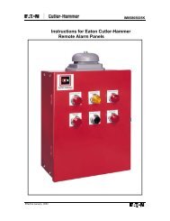
MODEL NUMBERING & IDENTIFICATION<br />
There are two identification plates attached to each<br />
engine. Clarke Identification Plate: Engine Model,<br />
Serial Number, Rating <strong>and</strong> Date of Manufacture are<br />
shown on this identification plate. The JU Series<br />
identification plate is mounted on the flywheel<br />
housing at the rear of the engine. The JW Series<br />
identification plate is mounted on right rear engine<br />
mount.<br />
Note that there are five types of identification plates,<br />
dependent on whether the engine is a “Non-Listed”<br />
or “Listed/Approved” Model. These are typical<br />
examples. (See Figure #1).<br />
Clarke Identification Plates<br />
USA Non Listed USA Listed/Approved<br />
UK Non-Listed UK Listed/Approved<br />
Figure #1
UK Listed/Approved<br />
Figure #1 cont’d<br />
Clarke model numbers reflects the base engine type,<br />
number of cylinders, cooling system, approval listing<br />
<strong>and</strong> a power rating code.<br />
Example: JU6H-UF50<br />
• J = John Deere base engine prepared by<br />
CLARKE<br />
• U = base engine series (4.5 liter 4 cylinder or<br />
6.8 liter 6 cylinder)<br />
• 6 = number of cylinders<br />
• H = Heat Exchanger cooled (R = Radiator)<br />
• UF = Underwriters Laboratories Listed/<br />
Factory Mutual Approved, (LP = LPCB Loss<br />
Prevention Council Board Approved, NL =<br />
Non-Listed)<br />
• 50 = A power rating code<br />
John Deere Identification Plate: The second<br />
identification plate contains the John Deere Model<br />
Number <strong>and</strong> Serial Number. On the JW Series, the<br />
John Deere Serial identification plate is located on<br />
the left-h<strong>and</strong> side of the engine between the intake<br />
manifold <strong>and</strong> starting motor. On the JU Series, the<br />
John Deere identification plate is located on the right<br />
side of the cylinder block behind the fuel filter.<br />
1.2 SAFETY/CAUTION/WARNINGS<br />
ATTENTION: This engine has components <strong>and</strong><br />
fluids that reach very high operating temperatures<br />
<strong>and</strong> is provided with moving pulleys <strong>and</strong> belts.<br />
Approach with caution. It is the responsibility of the<br />
builder of the machine using a Clarke engine to<br />
optimize the application in terms of maximum end<br />
user safety.<br />
Page 6 of 38<br />
BASIC RULES<br />
The following recommendations are given to reduce<br />
the risk to persons <strong>and</strong> property when an engine is in<br />
service or out of service.<br />
Engines must not be used for applications other than<br />
those declared under “Scope of Supply”.<br />
Incorrect h<strong>and</strong>ling, modifications <strong>and</strong> use of nonoriginal<br />
parts may affect safety. When lifting the<br />
engine, take care to use suitable equipment to be<br />
applied to the points specially provided as shown on<br />
the appropriate Engine Installation Drawing. Engine<br />
weights are shown in figure #2<br />
ENGINE MODEL WEIGHT lbs (kg)<br />
910 (413)<br />
JU4H-UF10, 12, 20, 22<br />
JU4H-NL20, 22<br />
JU4H-LP20,24<br />
JU4H-UF30, 32, 40, 42, 50, 52,<br />
8H, H0, H2, 58<br />
JU4H-NL30, 32, 40, 42<br />
JU4H-LP50,54<br />
935 (424)<br />
JU4H-LP84 1085 (492)<br />
JU4R-UF09, UF11,13,19,21,23 956 (434)<br />
JU4R-UF40, 49, 51, 53 982 (445)<br />
JU6H-UF30, 32, 50, 52<br />
D0, D2, G8, M8, M0, M2, 58<br />
JU6H-NL30, 32, 50, 52<br />
JU6H-LP50,54<br />
JU6H-UF60, 62, 68<br />
JU6H-LP60,84<br />
JW6H-UF30 (JDFP-06WA), 38<br />
JW6H-NL30<br />
JW6H-UF40 (JDFP-06WR), 48<br />
JW6H-NL40<br />
JW6H-UF50, 60, 58<br />
JW6H-NL50, 60<br />
Figure #2<br />
1657 (750)<br />
1693 (766)<br />
2012 (910)<br />
2003 (906)<br />
2053 (929)<br />
Figure #3 shows the typical lifting arrangement of a<br />
bare engine. Note the lifting points on the engine are<br />
for lifting the engine only. Caution, when lifting, lift<br />
point should always be over the equipment Center of<br />
Gravity.
Figure #3<br />
Figure #4 shows the typical lifting arrangement of a<br />
base mounted engine <strong>and</strong> pump set when the base (or<br />
module) is furnished with lifting holes.<br />
Figure #4<br />
Page 7 of 38<br />
When Clarke furnishes the base (or module) for the<br />
engine <strong>and</strong> pump set, the combined weight of the<br />
engine <strong>and</strong> base (or module) will be indicated on the<br />
unit. Caution, when lifting, lift point should<br />
always be over the equipment Center of Gravity.<br />
Note: The engine produces a noise level exceeding<br />
70 dB(a). When performing the weekly functional<br />
test, it is recommended that hearing protection be<br />
worn by operating personnel.<br />
CLARKE UK provides the machine manufacturer<br />
with a “Declaration of Incorporation”<br />
for the Engine, when required, a copy of which is<br />
enclosed in the manual. This document clearly states<br />
the machine manufacturers’ duties <strong>and</strong><br />
responsibilities with respect to health <strong>and</strong> safety.<br />
Refer to Figure #5.
GRANGE WORKS, LOMOND ROAD, COATBRIDGE, UNITED KINGDOM, ML5 2NN<br />
DECLARATION OF INCORPORATION<br />
Page 8 of 38<br />
TEL: 0044 1236 429946<br />
FAX: 0044 1236 427274<br />
We hereby declare that the following engine is intended to be incorporated into other machinery <strong>and</strong> must not be put into service until<br />
the relevant machinery, into which it is to be incorporated has been declared in conformity with the essential health <strong>and</strong> safety<br />
requirements of the Machinery Directive 89/392/EEC.<br />
Description: - DIESEL ENGINES<br />
Model: -<br />
Serial Number: -<br />
Contract No: -<br />
Customers order no:<br />
NOTE: - This engine has moving parts, areas of high temperatures, <strong>and</strong> high temperature fluids under pressure. In addition it has an<br />
electrical system, which may be under strong current.<br />
The engine produces harmful gases, noise vibrations <strong>and</strong> as a result it is necessary to take Suitable precautionary measures when moving,<br />
installing <strong>and</strong> operating the engine to reduce risks connected with the characteristics stated above.<br />
The engine must only be used in accordance with the scope of supply <strong>and</strong> the intended application.<br />
STANDARDS AND TECHNICAL SPECIFICATIONS<br />
Signed: ____________________________ Date: ____________________________<br />
C13896, Rev C, 3 Jan 2003<br />
WHAT TO DO IN AN EMERGENCY<br />
Any user of the Engine who follows the instructions<br />
set out in this manual, <strong>and</strong> complies with the<br />
instructions on the labels affixed to the engine are<br />
working in safe conditions.<br />
If operating mistakes cause accidents call for help<br />
If operating mistakes cause accidents call for help<br />
immediately from the EMERGENCY SERVICES.<br />
In the event of an emergency, <strong>and</strong> while awaiting the<br />
arrival of the EMERGENCY SERVICES, the<br />
REGISTERED IN SCOTLAND NO: 81670<br />
Figure #5<br />
following general advice is given for the provision of<br />
first aid.<br />
FIRE<br />
Put out the fire using extinguishers recommended by<br />
the manufacturer of the machine or the installation.<br />
BURNS<br />
1) Put out the flames on the clothing of the<br />
burns victim by means of:<br />
� drenching with water
� use of powder extinguisher, making<br />
sure not to direct the jets onto the<br />
face<br />
� blankets or rolling the victim on the<br />
ground<br />
2) Do not pull off strips of clothing that are<br />
sticking to the skin.<br />
3) In the case of scalding with liquids, remove<br />
the soaked clothing quickly but carefully.<br />
4) Cover the burn with a special anti-burn<br />
packet or with a sterile b<strong>and</strong>age.<br />
CARBON MONOXIDE POISONING (CO)<br />
Carbon monoxide contained in engine exhaust gases<br />
is odorless <strong>and</strong> dangerous because it is poisonous <strong>and</strong><br />
with air, it forms an explosive mixture.<br />
Carbon monoxide is very dangerous in enclosed<br />
premises because it can reach a critical concentration<br />
in a short time.<br />
When attending a person suffering from CO<br />
poisoning in enclosed premises, ventilate the<br />
premises immediately to reduce the gas<br />
concentration.<br />
When accessing the premises, the person providing<br />
the aid must hold his breath, not light flames, turn on<br />
lights or activate electric bells or telephones so as to<br />
avoid explosions.<br />
Take the victim to a ventilated area or into the open<br />
air, placing him on his side if he is unconscious.<br />
CAUSTIC BURNS<br />
1) Caustic burns to the skin are caused by acid<br />
escaping from the batteries:<br />
� remove the clothes<br />
� wash with running water, being<br />
careful not to affect injury-free areas<br />
2) Caustic burns to the eyes are caused by<br />
battery acid, lubricating oil <strong>and</strong> diesel fuel.<br />
� Wash the eye with running water for<br />
at least 20 minutes, keeping the<br />
eyelids open so that the water runs<br />
over the eyeball <strong>and</strong> moving the eye<br />
in all directions.<br />
Page 9 of 38<br />
ELECTROCUTION<br />
Electrocution can be caused by:<br />
1) The engine’s electrical system (12/24<br />
VDC)<br />
2) The electrical coolant pre-heating system<br />
120/240 Volt AC (if supplied) AC current.<br />
In the first case, the low voltage does not involve<br />
high current flows through the human body;<br />
however, if there is a short circuit, caused by a metal<br />
tool, sparks <strong>and</strong> burns may occur.<br />
In the second case, the high voltage causes strong<br />
currents, which can be dangerous.<br />
If this happens, break the current by operating the<br />
switch before touching the injured person.<br />
If this is not possible, bear in mind that any other<br />
attempt is highly dangerous also for the person<br />
assisting; therefore, any attempt to help the victim<br />
must be carried out without fail using means that are<br />
insulating.<br />
WOUNDS AND FRACTURES<br />
The wide range of possible injuries <strong>and</strong> the specific<br />
nature of the help needed means that the medical<br />
services must be called.<br />
If the person is bleeding, compress the wound<br />
externally until help arrives.<br />
In the case of fracture do not move the part of the<br />
body affected by the fracture. When moving an<br />
injured person permission from that person must be<br />
received until you can help him. Unless the injury is<br />
life threatening, move the injured person with<br />
extreme care <strong>and</strong> then only if strictly necessary.<br />
WARNING LABELS<br />
Warning labels, in picture form, are applied to the<br />
engine. Their meanings are given below.<br />
Important Note: Labels that show an exclamation<br />
mark indicate that there is a possibility of danger.
Heat Exchanger Maximum Working Pressure<br />
Coolant Mixture<br />
Lifting Point<br />
Automatic Start<br />
Rotating Parts<br />
Page 10 of 38<br />
Jacket Water Heater Voltage<br />
Air Filter Installation<br />
2.0 INSTALLATION/OPERATION<br />
2.1 TYPICAL INSTALLATION<br />
A typical Fire Pump installation is shown in Figure<br />
#6 & 6A.<br />
1. Pump/Engine set<br />
2. Main Pump Controller<br />
3. Pump discharge<br />
4. Air louver<br />
5. Entrance door with air louver<br />
6. Exhaust silencer<br />
7. Exhaust system supports<br />
8. Exhaust outlet pipe<br />
9. Concrete base<br />
10. Exhaust flexible connection joint/pipe<br />
11. Air Discharge Duct from Radiator<br />
Figure #6<br />
Typical Installation<br />
Heat Exchanger Cooled Engine
2.2 ENGINE STORAGE<br />
Figure #6A<br />
Typical Installation<br />
Radiator Cooled Engine<br />
2.2.1 Storage less than 1 year<br />
Storing engines requires special attention. Clarke<br />
engines, as prepared for shipment, may be stored for<br />
a minimum of one year. During this period, they<br />
should be stored indoors in a dry environment.<br />
Protective coverings are recommended provided they<br />
are arranged to allow for air circulation. The stored<br />
engine should be inspected periodically for obvious<br />
conditions such as st<strong>and</strong>ing water, part theft, excess<br />
dirt buildup or any other condition that may be<br />
detrimental to the engine or components.<br />
Any such conditions found must be corrected<br />
immediately.<br />
2.2.2 Extended Storage <strong>Maintenance</strong> Procedure<br />
11<br />
After a one year storage period or if the engine is<br />
being taken out of service for more than 6 months,<br />
additional preservation service must be performed as<br />
follows:<br />
1) Drain the engine oil <strong>and</strong> change the oil filter.<br />
2) Refill the engine crankcase with MIL-L-<br />
21260 preservative oil.<br />
3) Change the fuel filter.<br />
4) Install the coolant plugs <strong>and</strong> install coolant in<br />
the normal mix percentage of 50% coolant,<br />
50% water, premixed.<br />
5) Remove the protection from the intake <strong>and</strong><br />
exhaust openings.<br />
6) Prepare a container as a fuel source using a<br />
mixture of Mobilarma or Sta-Bil with Diesel<br />
#2 fuel or “Red” diesel fuel (ASTM D-975)<br />
or BS2869 Class A2.<br />
7) Disconnect the coupling or drive shaft from<br />
the pump.<br />
Page 11 of 38<br />
8) Start <strong>and</strong> run the engine at a slow speed for<br />
1-2 minutes being careful not to exceed the<br />
normal operating temperature.<br />
9) Drain the oil <strong>and</strong> coolant.<br />
10) Replace the protective plugs that were used<br />
for shipping <strong>and</strong> storage.<br />
11) Attach to the engine a visible card, specifying<br />
“ENGINE WITHOUT OIL” DO NOT<br />
OPERATE”.<br />
IMPORTANT: THIS TREATMENT MUST BE<br />
REPEATED EVERY 6 MONTHS<br />
************************<br />
PUTTING ENGINE INTO SERVICE AFTER<br />
ADDITIONAL PRESERVATION SERVICE:<br />
To restore the normal operation running conditions of<br />
the engine, carry out the following:<br />
1) Fill the engine sump with the normal<br />
recommended oil, to the required level.<br />
2) Remove the protective plugs used for<br />
shipping <strong>and</strong> storage.<br />
3) Refill cooling water to proper level.<br />
4) Remove the card “ENGINE WITHOUT OIL,<br />
DO NOT OPERATE”.<br />
5) Follow all steps of the Installation<br />
<strong>Instructions</strong> when the engine will be put into<br />
service.<br />
2.3 INSTALLATION INSTRUCTIONS<br />
The correct installation of the engine is very<br />
important to achieving optimum performance <strong>and</strong><br />
extended engine life.<br />
In this respect, the engine has certain installation<br />
requirements, which are critical to how it performs.<br />
These requirements are generally associated with the<br />
cooling, exhaust, induction air, <strong>and</strong> fuel systems.<br />
This section of the manual should be read in<br />
conjunction with the relevant Installation <strong>and</strong><br />
<strong>Operation</strong> Data Sheets. If there is any doubt about an<br />
installation, contact should be made with Clarke<br />
Customer Support giving exact details of the<br />
problem.<br />
All installations should be clean, free of any debris<br />
<strong>and</strong> dry. Care should be taken to ensure that there is<br />
easy access to the engine for maintenance <strong>and</strong> repair.<br />
The safety of personnel who may be in the area of the
engine when it is running is of paramount importance<br />
when designing the installation layout.<br />
1) Secure pump set to foundation <strong>and</strong> complete<br />
installation in accordance with pump<br />
manufacturer’s instructions. Perform engineto-pump<br />
coupling alignment. Lubricate Falk<br />
coupling with supplied grease or driveshaft<br />
universal joints with NLGI grade #1 or #2<br />
grease at the (3) Zerk fittings. (Refer to<br />
section 2.4 for specific alignment<br />
instructions).<br />
2a) Engine with Heat Exchanger Cooling:<br />
Install the heat exchanger discharge pipe.<br />
The discharge pipe should be no smaller than<br />
the outlet connection on the heat exchanger.<br />
Discharge water piping should be installed in<br />
accordance with applicable codes. All<br />
plumbing connecting to the heat exchanger<br />
must be secured to minimize movement by<br />
the engine. Cooling loop water pressure to<br />
the heat exchanger must not exceed the limit<br />
that is stated on the heat exchanger supplied<br />
with the engine.<br />
2b) Engine with Radiator Cooling:<br />
Connect radiator air discharge ducting to<br />
radiator duct flange. Discharge ducting<br />
should be installed in accordance with<br />
applicable codes. A flexible duct section<br />
should be provided to isolate engine from<br />
building.<br />
3) Install all engine cooling system draincocks<br />
<strong>and</strong> plugs.<br />
Engine<br />
Qty Description Location Model<br />
1 1/8” Water Heater JU4/6H,<br />
draincock inlet tube JU4/6R<br />
1 1/8” Coolant heater JDFP,<br />
draincock inlet tube JW6<br />
1 Plug Oil Cooler JU4/6H,<br />
RE46686<br />
JU4/6R<br />
1 3/8” pipe plug Heat exchanger JDFP,<br />
JW6<br />
1 Electrode Bottom of heat JU4/6H<br />
plug exchanger<br />
4) Fill engine cooling system with premixed<br />
50% water / 50% coolant solution. Use only<br />
coolants meeting ASTM-D4985<br />
specifications for heavy-duty diesel engines.<br />
Never use light-duty or automotive coolants<br />
in the engine that are stated as ASTM-D3306<br />
only. Refer to Figure #34 in section 3.4.3<br />
Page 12 of 38<br />
for cooling system capacity. Refer to section<br />
3.4.5 for filling procedure.<br />
5) Engine is shipped with oil installed. For<br />
make-up oil specification refer to section 3.3<br />
Lubrication System.<br />
6) Connect fuel supply <strong>and</strong> return line to fuel<br />
supply tank plumbing. Reference the Fuel<br />
System section of the Installation <strong>and</strong><br />
<strong>Operation</strong> Data in the Technical Catalog, for<br />
piping size, maximum allowable fuel pump<br />
suction, <strong>and</strong> maximum allowable fuel head<br />
requirements. Fill supply tank with #2 diesel<br />
fuel (ASTM D-975) or BS 2869 Class A2<br />
“Red” diesel fuel, bleed supply system of air<br />
<strong>and</strong> check for leaks. Fuel supply level must<br />
meet applicable code requirements. Do not<br />
use a copper based or galvanized material for<br />
any component of a diesel fuel system. The<br />
fuel will chemically react with the zinc<br />
resulting in clogged fuel filters <strong>and</strong> injector<br />
systems.<br />
7) Remove protective covering on air cleaner<br />
element.<br />
8) Connect jacket water heater (if supplied) to<br />
AC power source. For JU4/6 Series the<br />
electrical supply requirements are indicated<br />
on the heater body. Connect the supplied<br />
heater connection wire directly to a customer<br />
supplied electrical junction box. For<br />
JDFP/JW6 Series the electrical supply<br />
requirements are indicated on the connection<br />
box. Connect to the heater directly to the<br />
junction box at the end of the heater only.<br />
Supply wiring should never be routed<br />
through the engine gauge panel. Severe<br />
damage to critical engine control components<br />
could result. Energize heater only after step<br />
#4 is completed.<br />
9) Connect exhaust system to flexible<br />
connection on the engine. The exhaust<br />
system plumbing must be supported by the<br />
building structure <strong>and</strong> not the engine. The<br />
exhaust flexible connection is provided only<br />
for the purpose of thermal expansion <strong>and</strong><br />
vibration isolation, not for misalignment or<br />
directional change.<br />
10) Make electrical DC connections between the<br />
engine gauge panel terminal strip (if<br />
supplied) <strong>and</strong> the controller per the controller<br />
manufacturer’s instructions. Note that the<br />
“W” terminal is used only for the UL/FM<br />
cooling water solenoid (if supplied). Refer to
the wiring diagram sticker located on the<br />
inside cover of the engine gauge panel for<br />
proper connection of the water solenoid.<br />
11) Fill batteries with electrolyte per battery<br />
manufacturer’s instructions. Connect cables<br />
between engine <strong>and</strong> batteries only after<br />
electrolyte is installed. Refer to the wiring<br />
diagram inside the engine gauge panel cover<br />
(if supplied), or appropriate wiring diagram<br />
in the Technical Catalog C13965, for correct<br />
positive <strong>and</strong> negative connections. Connect<br />
negative cables directly to the engine block.<br />
On JU4/6 Series connect each positive cable<br />
to the large electrical post of the starter<br />
motor. Note: the JU4/6 Series have a<br />
separate starter motor for each battery set.<br />
On the JDFP/JW6 Series connect each<br />
positive cable to the large outer post of the<br />
manual starting contactors.<br />
12) Note: Clarke <strong>Operation</strong> <strong>and</strong> <strong>Maintenance</strong><br />
<strong>Instructions</strong> <strong>Manual</strong> <strong>and</strong> Clarke parts<br />
illustration pages are located inside the<br />
engine gauge panel.<br />
13) IMPORTANT! In order to obtain prompt<br />
Warranty Service <strong>and</strong> to comply with<br />
Emissions Regulations, this engine must be<br />
registered to the final installation name <strong>and</strong><br />
address. To register this engine, go to<br />
www.clarkefire.com <strong>and</strong> select Warranty<br />
Registration.<br />
2.4 SPECIFIC FLYWHEEL COUPLING<br />
ALIGNMENT INSTRUCTIONS<br />
2.4.1 Driveshaft<br />
To check the alignment of the pump shaft <strong>and</strong> engine<br />
crankshaft centerlines for proper Parallel Offset <strong>and</strong><br />
Angular tolerance, the driveshaft must be installed<br />
between the flywheel drive disc (no drive disc on<br />
JW6 models) <strong>and</strong> the flanged hub on the pump shaft.<br />
Before removing the driveshaft guard, disconnect the<br />
negative battery cable from both batteries.<br />
Before beginning the alignment checks <strong>and</strong> making<br />
any necessary corrections, install the driveshaft <strong>and</strong><br />
re-torque all driveshaft connection bolts to the values<br />
given in the following table:<br />
Page 13 of 38<br />
MODELS<br />
JU4-UF09,<br />
10,11,12,13,19,<br />
20,2122,23<br />
JU4-LP 20,24<br />
JU4-UF<br />
30,32,40,42,50,<br />
51,52,53, H8,<br />
H0, H2, 58<br />
JU4-LP 50,54<br />
All JU6<br />
& JW6<br />
DRIVE<br />
SHAFT<br />
SC41<br />
SC55<br />
SC2130<br />
BOLT SIZE<br />
/MATERIAL<br />
GRADE<br />
7/16-20<br />
Grade 8<br />
(Hi-Tensile)<br />
1/2-20<br />
Grade 8<br />
(Hi-Tensile)<br />
M12,Class<br />
10.9<br />
(Metric)<br />
(Hi-Tensile)<br />
TIGHTENIN<br />
G TORQUE<br />
ft-lbs<br />
(N-m)<br />
50 + 55<br />
(68 – 75)<br />
75 + 82.5<br />
(102 – 112)<br />
90 + 99<br />
(122 – 134)<br />
(see note #1)<br />
86 – 94<br />
(117 - 128)<br />
(see note #2)<br />
Note 1 – It is recommended that a medium strength<br />
threadlocker (i.e. Loctite – blue #64040) be used in<br />
the assembly <strong>and</strong> torquing of all hardware. This may<br />
be purchased as part number 23509536.<br />
Note 2 – 4 of the hi-tensile bolts <strong>and</strong>/or nuts, that are<br />
used to connect the driveshaft to the drive disc (all<br />
JU6 models) or flywheel (all JW6 models) <strong>and</strong> that<br />
connect the driveshaft to the pump companion flange,<br />
will require a “crow’s foot” wrench attached to a<br />
st<strong>and</strong>ard torque wrench in order to apply the required<br />
tightening torque. A st<strong>and</strong>ard socket will not work<br />
due to close proximity of the bolts <strong>and</strong>/or nuts with<br />
the driveshaft yoke. The tightening torque values<br />
listed for these bolts <strong>and</strong>/or nuts have been corrected<br />
for using a st<strong>and</strong>ard “crow’s foot” adapter.<br />
The following steps describe the proper way to check<br />
alignment. A small pocket scale or ruler with<br />
millimeter markings is recommended to make all<br />
measurements.<br />
A) To check the Horizontal Parallel Offset, the<br />
driveshaft must be in the proper orientation.<br />
1. Rotate the shaft so the reference “AB” on the<br />
flywheel disc or the circumference of the<br />
drive shaft flange (against the flywheel) is in<br />
the 12 o’clock position shown on figure# 7.<br />
2. Measure from the rear face of the flywheel<br />
drive disc or the drive shaft flange to point A.<br />
(Point A is on the bearing bore as shown in
Figure 7, on the instrument panel side of the<br />
engine). This measurement must be:<br />
MEASUREMENT MODELS<br />
58 + 2mm. JU4-UF<br />
09,10,11,12,13,19, 20,<br />
21,22,23<br />
JU4-LP20,24<br />
68 + 4mm. JU4-UF30, 32, 40, 42,<br />
49, 50, 51, 52, 53, 8H,<br />
H0, H2, 58<br />
JU4-LP 50,54<br />
76 + 3mm. All JU6 & JW6<br />
B) With the driveshaft in the same orientation as the<br />
previous step (Step A), check the Horizontal<br />
Angular alignment of the shafts.<br />
1. Measure from the front face of the drive shaft<br />
flange on the pump end to point B. (Point B<br />
is the bearing bore on the exhaust side of the<br />
engine). This measurement must be equal to<br />
the measurement at point A + 1 mm.<br />
C) To check the Vertical Parallel Offset, the<br />
driveshaft must be re-orientated.<br />
1. Rotate the shaft 90 ○ so the reference “CD” on<br />
the flywheel drive disc or the circumference<br />
of the drive shaft flange (against the<br />
flywheel) is in the position shown on<br />
Figure#8.<br />
2. Measure from the rear face of the flywheel<br />
drive disc or the drive shaft flange to point C.<br />
(Point C is the same as point A with the<br />
driveshaft rotated 90°). The measurement<br />
must be:<br />
MEASUREMENT MODELS<br />
60 + 1mm. JU4-UF 09,10,11,12,13,<br />
20,21,22,23<br />
JU4-LP20,24<br />
71 + 1mm. JU4-UF30, 32, 40, 42,<br />
49,50,51,52,53, 8H, H0,<br />
H2, 58<br />
JU4-LP 50,54<br />
78 + 1mm. All JU6 & JW6<br />
D) With the driveshaft in the same orientation as the<br />
previous step (Step C), check the Vertical<br />
alignment of the shafts.<br />
1. Measure the front face of the drive shaft<br />
flange on the pump end to point D. (Point D<br />
is the same as point B, with the driveshaft<br />
rotated 90). The measurement must be equal<br />
to the measurement at point C + 1 mm.<br />
Re-install all guards <strong>and</strong> grease fittings vefore<br />
reconnecting the battery cables.<br />
Page 14 of 38<br />
Figure #7<br />
Figure #8<br />
DRIVESHAFT MAINTENANCE<br />
1. To service the driveshaft disconnect the<br />
negative battery cables, remove the top of<br />
guard <strong>and</strong> set aside.<br />
2. Rotate engine shaft manually so the u-joint<br />
grease fittings are accessible.<br />
3. Using a h<strong>and</strong> held grease gun with N.L.G.I.<br />
grade 1 or 2 grease position on grease fitting.<br />
Pump with grease until grease is visible at all<br />
four cap seals.<br />
4. Verify all driveshaft connecting bolts remain<br />
tight. Re-torque per 2.4.1 if necessary.<br />
5. Reinstall top of guard <strong>and</strong> connect negative<br />
battery cables.<br />
2.4.2 Other Coupling Types<br />
Consult Factory or Clarke website at<br />
www@clarkefire.com for additional<br />
information.
2.5 WEEKLY TEST<br />
An experienced operator should be present during the<br />
weekly test.<br />
NOTE: This engine is designed to operate at rated<br />
load conditions. For testing purposes the engine can<br />
be run at lower load (lower flow) conditions.<br />
Running times in any one period should not exceed<br />
30 minutes maximum.<br />
Before starting the engine make sure of the<br />
following:<br />
1) The operator has free access to stop the<br />
engine in an emergency.<br />
2) The plant room ventilation ducts are open<br />
<strong>and</strong> the engine has good access for air.<br />
3) All the guards are in position <strong>and</strong>, if not, for<br />
whatever reason, any rotating parts will be<br />
free <strong>and</strong> clear without restriction.<br />
4) Battery covers are in place <strong>and</strong> there is<br />
nothing on top of or touching the engine,<br />
which is not part of the original supply<br />
specification.<br />
5a) Heat Exchanger Cooling: The water supply<br />
for coolant is available again without<br />
restriction.<br />
5a) Radiator Cooling: The air supply for cooling<br />
is available again without restriction.<br />
When engine is running make sure that the coolant<br />
temperature <strong>and</strong> oil pressure raw cooling water flow<br />
are within the limits specified on the relevant<br />
Installation & <strong>Operation</strong> Data Sheet in the Technical<br />
Catalog, C13965.<br />
If the coolant temperature is excessive, check:<br />
a) Cooling loop strainers<br />
b) Proper functioning of thermostat<br />
c) Condition of heat exchanger tube bundle<br />
2.6 STARTING/STOPPING THE ENGINE<br />
2.6.1 Special Notes to Equipment Installer of an<br />
LPCB Approved (LPS1239) Engine Model<br />
Any device fitted to the engine or controller, which<br />
could prevent the engine starting automatically, shall<br />
Page 15 of 38<br />
return automatically to the normal position after<br />
manual application. The electrical fuel shutoff<br />
actuator shall be connected to an Engine Stop button<br />
on the main pump controller.<br />
The main pump controller shall de-energize the start<br />
motor when the engine has achieved 700-1000 rpm.<br />
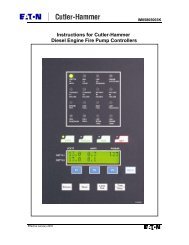
2.6.2 To Start Engine<br />
Use main pump controller for starting. Follow<br />
instructions provided by controller manufacturer.<br />
On UL/FM engines, use main pump controller for<br />
starting <strong>and</strong> stopping the engine. Should the main<br />
pump controller become inoperable, the engine can<br />
be manually started <strong>and</strong> stopped from the engine<br />
gauge panel. For manual starting <strong>and</strong> stopping of an<br />
engine with a gauge panel: Position MODE<br />
SELECTOR to MANUAL RUN. (Refer to Figure<br />
#9). Lift <strong>and</strong> hold MANUAL CRANK #1, until<br />
engine starts, or release after 15 seconds. If unit fails<br />
to start, wait for 15 seconds, use MANUAL CRANK<br />
#2 <strong>and</strong> repeat step. If COOLING WATER is not<br />
flowing or engine TEMPERATURE is too HIGH,<br />
open cooling system manual by-pass valves (applies<br />
to heat exchanger cooled engines only).<br />
Note: On JW Engines you can also start engines<br />
using manual starting contactors.<br />
On LPCB engines, use main pump controller for<br />
starting <strong>and</strong> stopping the engine. Should the main<br />
pump controller become inoperable, the engine can<br />
be manually started from the engine gauge panel.<br />
For manual starting of an engine with a gauge panel.<br />
(Refer to Figure #9A): Lift <strong>and</strong> hold MANUAL<br />
CRANK #1, until engine starts, or release after 15<br />
seconds. If unit fails to start, wait for 10 seconds, use<br />
MANUAL CRANK #2 <strong>and</strong> repeat step. If<br />
COOLING WATER is not flowing or engine<br />
TEMPERATURE is too HIGH, open cooling<br />
system manual by-pass valves (applies to heat<br />
exchanger cooled engines only).
UL/FM Instrument Panel<br />
Figure #9<br />
1 – Emergency Operating <strong>Instructions</strong> 4 – Overspeed Reset<br />
2 – Automatic-<strong>Manual</strong> Mode Selector 5 – Warning Light<br />
3 – <strong>Manual</strong> Crank Controls 6 – Overspeed Verification<br />
Page 16 of 38
1<br />
LPCB Instrument Panel<br />
Figure #9A<br />
1 – Emergency Operating <strong>Instructions</strong><br />
2 – <strong>Manual</strong> Crank Controls<br />
Page 17 of 38<br />
2<br />
2 2
IMPORTANT: Main pump controller selector<br />
should be in the OFF position when starting from<br />
engine gauge panel. Be sure to return selector on<br />
main pump controller <strong>and</strong> engine gauge panel to<br />
AUTOMATIC after completing manual run.<br />
2.6.3 To Stop Engine<br />
If engine is started from main pump controller use<br />
main pump controller to stop the engine.<br />
If engine is started from engine gauge panel: Return<br />
MODE SELECTOR switch to<br />
AUTOMATIC/MANUAL STOP position, engine<br />
will stop. Close cooling system manual by-pass<br />
valve if opened.<br />
IMPORTANT: DO NOT leave the MODE<br />
SELECTOR switch in the MANUAL RUN position<br />
during AUTOMATIC operation. (The controller<br />
will be unable to stop the engine <strong>and</strong> DAMAGE<br />
MAY RESULT).<br />
Engines not equipped with an engine gauge panel,<br />
<strong>and</strong> LPCB engines, have a manual shutdown lever<br />
on the engine for shutdown.<br />
3.0 ENGINE SYSTEMS<br />
3.1 FUEL SYSTEM<br />
3.1.1 Bleeding the Fuel System<br />
CAUTION: Escaping fluid under pressure can<br />
penetrate the skin causing series injury. Relieve<br />
pressure before disconnecting fuel or other lines.<br />
Tighten all connections before applying pressure.<br />
Keep h<strong>and</strong>s <strong>and</strong> body away from pinholes <strong>and</strong><br />
nozzles, which eject fluids under high pressure.<br />
Use a piece of cardboard or paper to search for<br />
leaks. Do not use your h<strong>and</strong>.<br />
If ANY fluid is injected into the skin, it must be<br />
surgically removed within a few hours by a doctor<br />
familiar with this type injury or gangrene may<br />
result. Doctors unfamiliar with this type of injury<br />
may call the Deere & Company Medical<br />
Department in Moline, Illinois, or other<br />
knowledgeable medical source. Ref figure #10<br />
Page 18 of 38<br />
Figure #10<br />
Whenever the fuel system has been opened up for<br />
service (lines disconnected or filters removed), it will<br />
be necessary to bleed air from the system.<br />
3.1.1.1 JU4/6-UF,NL Engine Series:<br />
1) Loosen the air bleed vent screw (A) two full<br />
turns by h<strong>and</strong> on fuel filter base. Ref. Figure<br />
#11<br />
2) Operate supply pump primer lever (B) until<br />
fuel flow is free from air bubbles. Ref.<br />
Figure #12.<br />
3) Tighten bleed plug securely; continue<br />
operating h<strong>and</strong> primer until pump action is<br />
not felt. Push h<strong>and</strong> primer inward (toward<br />
engine) as far as it will go.<br />
4) Start engine <strong>and</strong> check for leaks.<br />
Figure #11<br />
A
Figure # 12<br />
If engine will not start, it may be necessary to bleed<br />
air from fuel system at fuel injection pump or<br />
injection nozzles as explained next.<br />
At Fuel Injection Pump:<br />
1) Slightly loosen fuel return line connector (A)<br />
at fuel injection pump. Ref figure #13<br />
2) Operate fuel supply pump primer lever until<br />
fuel, without air bubbles, flows from fuel<br />
return line connection.<br />
3) Tighten return line connector at 16N-m (12<br />
lb-ft).<br />
4) Leave h<strong>and</strong> primer in the inward position<br />
toward cylinder block. Ref. Figure #14.<br />
B<br />
Figure # 13<br />
A<br />
Page 19 of 38<br />
Figure #14<br />
3.1.1.2 JU4/6 LP Engine Series<br />
Photo to follow later<br />
3.1.1.3 JDFP/JW6 Engine Series:<br />
Refer to Figure #19 for system components location.<br />
A – Primary Fuel Filter<br />
B – Secondary Fuel Filter<br />
C – Fuel Injection Pump<br />
D – Speed Adjustment<br />
At Round Primary Fuel Filter/Water Separator:<br />
1) Drain water <strong>and</strong> contaminants from clear<br />
sediment bowl.<br />
2) Loosen air bleed vent screw (A) on fuel filter<br />
base (Figure# 15)<br />
3) Operate <strong>and</strong> primer (B) until fuel flow is free<br />
from air bubbles (Figure#15)<br />
4) Tighten vent screw as h<strong>and</strong> primer is held in<br />
downward pumping position.<br />
B
A<br />
Figure # 15<br />
At Rectangular Final Fuel Filter:<br />
1) Loose bleed plug (A) on fuel filter base<br />
(figure#16).<br />
2) Operate h<strong>and</strong> primer (B) on fuel supply<br />
pump (figure#17), until a smooth flow of<br />
fuel, free of bubbling, comes out of the plug<br />
hole.<br />
3) Simultaneously stroke the h<strong>and</strong> primer down<br />
<strong>and</strong> close the filter port plug. This prevents<br />
air from entering the system. Tighten plug<br />
securely. DO NOT over tighten.<br />
4) Start engine <strong>and</strong> check for leaks.<br />
A<br />
Figure #16<br />
Page 20 of 38<br />
B<br />
Figure #17<br />
If engine will not start, it may be necessary to bleed<br />
air from fuel system at injection nozzles as explained<br />
below.<br />
At Fuel Injection Nozzle<br />
1) Loosen fuel line connection at no. 1 injection<br />
nozzle (A) (figure#18)<br />
2) Crank engine with starting motor (but do not<br />
start engine), until fuel free from bubbles<br />
flows out of loosened connections. Retighten<br />
connection.<br />
3) Start engine <strong>and</strong> check for leaks.<br />
4) If engine does not start, repeat procedure at<br />
remaining injection nozzles (if necessary)<br />
until enough air has been removed from fuel<br />
system to allow engine to start.<br />
Figure #18<br />
A
B<br />
A<br />
Figure #19<br />
3.1.2 Draining the Condensate from the Fuel Filter<br />
Drain the condensate from the fuel filter. Fuel filters<br />
have a drain (B) located at the bottom of their body<br />
(A) figure#20, these filters should be drained each<br />
week to relieve built up water.<br />
B<br />
Figure #20<br />
3.1.3 Changing the Fuel Filter Cartridges<br />
Changing the cartridges <strong>and</strong> bleed any air from the<br />
fuel system as per instructions given in section 3.1.1.<br />
Fuel filter changes should take place as per<br />
recommendations <strong>and</strong> only using approved filters. It<br />
may also be necessary to change filters out with the<br />
recommendations in the event of:<br />
D<br />
1) The engine has had an overhaul.<br />
2) The quality of the fuel is questionable.<br />
3) The engine has been subjected to temporary<br />
adverse conditions outwith it normal<br />
operating parameters.<br />
A<br />
C<br />
Page 21 of 38<br />
4) The fuel tank condensation trap has not been<br />
drained in line with manufacturer’s<br />
recommendations.<br />
3.1.3.1 JU4/6-UF,NL Engine Series<br />
1) Close fuel shut-off valve, if equipped<br />
2) Thoroughly clean fuel filter assembly <strong>and</strong><br />
surrounded area.<br />
3) Loosen drain plug (C) <strong>and</strong> drain fuel into a<br />
suitable container. Ref figure#21<br />
Note: Lifting up on retaining ring <strong>and</strong> rotate it helps<br />
to get past raised locators.<br />
4) Firmly grasp the retaining ring (A) <strong>and</strong> rotate<br />
it counterclockwise ¼ turn. Remove ring<br />
with filter element (B). Ref figure#21<br />
5) Inspect filter mounting base for cleanliness.<br />
Clean as required.<br />
Note: Raised locators on fuel filter canister must be<br />
indexed properly with slots in mounting base for<br />
correct installation.<br />
6) Install new filter element onto mounting<br />
base. Be sure element is properly indexed<br />
<strong>and</strong> firmly seated on base. It may be<br />
necessary to rotate filter for correct<br />
alignment.<br />
If equipped with water separator, remove filter<br />
element from water separator bowl. Drain <strong>and</strong> clean<br />
separator bowl. Dry with compressed air. Install<br />
water separator bowl onto new element. Tighten<br />
securely.<br />
7) Align keys on filter element with slots in<br />
filter base.<br />
8) Install retaining ring onto mounting base<br />
making certain dust seal is in place on filter<br />
base. H<strong>and</strong> tighten ring (about 1/3 turn) until<br />
it “snaps” into the detent. DO NOT over<br />
tighten retaining ring.<br />
Note: The proper installation is indicated when a<br />
“click” is heard <strong>and</strong> a release of the retaining ring is<br />
felt.<br />
A plug is provided with the new element for plugging<br />
the used element.
9) Open fuel shut-off valve <strong>and</strong> bleed the fuel<br />
system. Tighten bleed plug (D). Reference<br />
Figure #21<br />
C<br />
Figure #21<br />
3.1.3.2 JU4/6 LP Engine Series<br />
3.1.3.3 JDFP/JW6 Engine Series<br />
D<br />
Each engine has two fuel filters. For the purpose of<br />
identity, the primary filter incorporates the<br />
transparent water separator.<br />
Replacing (round) Primary Fuel Filter/Water<br />
Separator<br />
1) Close fuel shut-off valve at bottom of fuel<br />
tank, if equipped.<br />
2) Thoroughly clean fuel filter/water separator<br />
assembly <strong>and</strong> surrounding area.<br />
Note: Lifting up on retaining ring (F) as it is rotated<br />
helps to get it past retaining dent. Ref. Figure #22<br />
3) Rotate retaining ring counterclockwise ¼<br />
turn. Remove ring with filter element.<br />
4) Remove water separator bowl (G) from filter<br />
element (E). Drain <strong>and</strong> clean separator bowl.<br />
Dry with compressed air. Ref. Figure #22<br />
Note: Notice raised locators on filter element. These<br />
locators insure proper alignment of filter element to<br />
filter base.<br />
5) Install water separator bowl onto new filter<br />
element. Tighten securely.<br />
6) Index filter element until longer, vertical<br />
locator (D) is oriented opposite mounting<br />
base. Insert filter element into base securely.<br />
B<br />
A<br />
Page 22 of 38<br />
It may be necessary to rotate filter for correct<br />
alignment. Ref. Figure #22<br />
7) Install retaining ring to filter base, making<br />
certain dust seal (C) is in place on filter base.<br />
Tighten retaining ring until it locks into<br />
detent position <strong>and</strong> a “click” sound can be<br />
heard. Ref. Figure #22<br />
8) Bleed fuel system.<br />
Figure #22<br />
Replacing (rectangular) Secondary Fuel Filter<br />
Element<br />
1) Close fuel shut-off valve at bottom of fuel<br />
tank, if equipped.<br />
2) Loosen bleed plug (C) on side of filter base.<br />
Remove drain plug (B) to drain from fuel<br />
filter. Ref. Figure #23<br />
Note: Keep a small container under drain plug to<br />
catch draining fuel.<br />
3) With fuel filter firm against base, lift up on<br />
top retaining spring <strong>and</strong> pull down on bottom<br />
retaining spring. Pull fuel filter off guide<br />
pins of fuel filter base <strong>and</strong> discard.<br />
4) Install new fuel filter onto guide pins of fuel<br />
filter base. Hold filter firmly against base.<br />
5) Secure bottom filter retaining spring first,<br />
then secure top retaining spring (four<br />
arrows).
6) Install new drawn plug, shown installed.<br />
Tighten bleed plug <strong>and</strong> drain plug securely.<br />
Do not over tighten.<br />
7) Open fuel shut-off valve <strong>and</strong> bleed the fuel<br />
system. Ref. Figure #23<br />
C<br />
B<br />
3.1.4 Fuel Tanks<br />
Figure #23<br />
Keep the fuel tank filled to reduce condensation to a<br />
minimum. Open drain at the bottom of the fuel tank<br />
once a week to drain off any possible water <strong>and</strong>/or<br />
sediment. Fill tank after each test run.<br />
Note: Per NFPA 25 st<strong>and</strong>ards, the fuel tank level<br />
must never be less than 67% of its capacity.<br />
3.1.5 JU4/6 Fuel Injection Pump Components<br />
THIS TAG IS SUPPLIED ON ALL JU4 AND JU6<br />
ENGINES<br />
The above tag is stamped to identify the “As<br />
Built” Components. Refer to the next two tables<br />
to identify:<br />
Table 1) Droop Spring Part Number by Engine<br />
Model <strong>and</strong> Speed.<br />
Table 2) Run-Stop Solenoid (Internal to Injection<br />
Pump) Part Number by engine voltage.<br />
Page 23 of 38<br />
MODEL<br />
JU4H-UF10<br />
JU4R-UF09<br />
JU4R-UF11<br />
JU4H-UF20<br />
JU4R-UF19<br />
JU4R-UF21<br />
JU4H-LP20<br />
JU4R-UF23<br />
JU4R-UF13<br />
JU4H-UF14<br />
JU4H-UF24<br />
JU4H-UF12<br />
JU4H-UF22<br />
JU4H-UF32<br />
JU4H-UF42<br />
JU4R-UF51<br />
JU4H-UF52<br />
JU4H-UFH2<br />
JU4H-UF34<br />
JU4H-UF44<br />
JU4H-UF54<br />
JU4R-UF53<br />
JU4H-LP54<br />
JU4H-UF84<br />
JU4H-UF30<br />
JU4H-UF40<br />
JU4R-UF40<br />
JU4H-UF50<br />
JU4H-UFH8<br />
JU4H-UFH0<br />
JU4H-UF58<br />
JU4R-UF49<br />
JU4H-LP50<br />
JU6H-UF30<br />
JU6H-UFD0<br />
JU6H-UFG8<br />
JU6H-UFM8<br />
JU6H-UFM0<br />
JU6H-UF58<br />
JU6H-UF50<br />
JU6H-UF68<br />
JU6H-UF60<br />
JU6H-LP50<br />
JU6H-LP60<br />
JU6H-UF32<br />
JU6H-UFD2<br />
JU6H-UFM2<br />
JU6H-UF52<br />
JU6H-UF62<br />
JU6H-UF34<br />
JU6H-UF54<br />
JU6H-UF84<br />
Injection Pump<br />
“Droop Spring” Part Number<br />
RPM 1760<br />
2100<br />
2350<br />
13563<br />
or<br />
C02353<br />
20357<br />
13558<br />
2350<br />
2600<br />
13563<br />
or<br />
C02353<br />
13563<br />
or<br />
C02353<br />
2800<br />
2960<br />
3000<br />
24339<br />
24339<br />
24339
Run-Stop Solenoid Part Number<br />
ETR ETS<br />
12 Volt SD26214 or SD26921 or<br />
C07853 C07827<br />
24 Volt SD26387 or SD26922 or<br />
Legend:<br />
C07826 C07828<br />
ETR – Energized to Run<br />
ETS – Energized to Stop<br />
SD # - Stanadyne Part Number<br />
C # - Clarke Part Number<br />
3.1.6 JW6 Fuel Injection Pump Components<br />
For Droop Spring <strong>and</strong> Run-Stop Solenoid (external to<br />
Injection Pump) part numbers consult factory.<br />
3.2 AIR/EXHAUST SYSTEM<br />
3.2.1 Ambient Conditions<br />
Clarke engines are tested in accordance with SAE<br />
J1349 (Clarke USA) or ISO 3046 (Clarke UK). In<br />
this capacity they may be derated to meet certain site<br />
conditions, failure to do so can seriously impede the<br />
performance of the engine <strong>and</strong> could lead to<br />
premature failure.<br />
3.2.2 Ventilation<br />
The engine must be provided with adequate<br />
ventilation to satisfy the requirements of the<br />
combustion system, radiator cooling systems where<br />
fitted, <strong>and</strong> allow adequate dissipation of radiated heat<br />
<strong>and</strong> crankcase emissions. For all this data refer to<br />
Installation & <strong>Operation</strong> Data in Technical Catalog,<br />
C13965. This data can be used for proper sizing of<br />
inlet <strong>and</strong> outlet louvers.<br />
3.2.3 St<strong>and</strong>ard Air Cleaner<br />
The st<strong>and</strong>ard air cleaner is a reusable type. Should a<br />
situation occur where the air cleaner becomes<br />
plugged with dirt (starving the engine of air), loss of<br />
power <strong>and</strong> heavy black smoke will result; the air<br />
cleaner should be serviced immediately. See figure<br />
#39 for air cleaner part numbers by Clarke Engine<br />
Model.<br />
CAUTION: Do not attempt to remove the air<br />
cleaner while an engine is running nor run the engine<br />
while the air cleaner is off. Exposed components<br />
could cause severe injury to personnel <strong>and</strong> major<br />
Page 24 of 38<br />
internal engine damage could occur should any<br />
foreign matter be drawn into the engine.<br />
The air cleaner manufacturer recommends the<br />
following:<br />
1. The pre-oiled reusable elements are serviced<br />
with a special oil. The elements can be<br />
serviced or replaced.<br />
2. Figure #24 shows the air filter service<br />
instructions.<br />
3. When servicing the element is not practical,<br />
you can improve filter efficiency by respraying<br />
with oil.<br />
NOTE: Do not attempt this while engine is running<br />
NOTE: Do not over oil the reusable element<br />
Figure #24
Figure #24 (cont’d)<br />
3.2.4 Crankcase Ventilation<br />
3.2.4.1 Open Crankcase Ventilation (Refer to<br />
fig#27b)<br />
Vapors which may form within the engine are<br />
removed from the crankcase <strong>and</strong> gear train<br />
compartment by a continuous, pressurized ventilation<br />
system.<br />
A slight pressure is maintained within the engine<br />
crankcase compartment. Vapors expelled through a<br />
vent pipe attached to the rocker cover breather<br />
element. Ref. Figure #25, 26, & 27.<br />
Figure #25<br />
JU4-UF10, 12, 20, 22, JU4-LP20, 24<br />
Page 25 of 38<br />
Figure #26<br />
JU4-UF30, 32, 40, 42, 50, 52, H8, H0, H2, 58<br />
JU4-LP50, 54 & JU6 All<br />
Figure #27<br />
JDFP/JW6<br />
3.2.4.2 Crankcase Ventilation System<br />
A crankcase ventilation system allows for the<br />
recirculation of vapors (expelled through a vent pipe<br />
attached to the rocker cover breather element) to the<br />
combustion air inlet. Refer to figure 27a.<br />
Figure #27a
Engine<br />
Model<br />
JU4R-UF09<br />
JU4H-UF10<br />
JU4R-UF11<br />
JU4H-UF12<br />
JU4R-UF19<br />
JU4H-UF20<br />
JU4H-LP20<br />
JU4R-UF21<br />
JU4H-UF22<br />
JU4R-UF23<br />
JU4H-UF30<br />
JU4H-UF32<br />
JU4H-UF40<br />
JU4R-UF40<br />
JU4H-UF42<br />
JU4R-UF49<br />
JU4H-UF50<br />
JU4H-LP50<br />
JU4R-UF51<br />
JU4H-UF52<br />
JU4H-UF58<br />
JU4H-UFH2<br />
JU4H-UFH8<br />
JU4H-UFH0<br />
JU6H-UF30<br />
JU6H-UF32<br />
JU6H-UF50<br />
JU6H-LP50<br />
JU6H-UF52<br />
JU6H-UF58<br />
JU6H-UF62<br />
JU6H-UF68<br />
JU6H-UF60<br />
JU6H-LP60<br />
JU6H-UFD0<br />
JU6H-UFG8<br />
JU6H-UFM8<br />
JU6H-UFM0<br />
JU6H-UFD2<br />
JU6H-UFM2<br />
Engine<br />
Model<br />
JU4H-UF34<br />
JU4H-UF44<br />
JU4H-UF54<br />
JU4R-UF53<br />
JU4H-LP54<br />
JU4H-UF84<br />
JU6H-UF34<br />
JU6H-UF54<br />
JU6H-UF84<br />
Open<br />
Crankcase<br />
Ventilation<br />
St<strong>and</strong>ard<br />
Figure #27b<br />
Open<br />
Crankcase<br />
Ventilation<br />
Figure #27b cont’d<br />
Crankcase<br />
Ventilation<br />
System<br />
Optional<br />
Crankcase<br />
Ventilation<br />
System<br />
St<strong>and</strong>ard<br />
Page 26 of 38<br />
3.2.5 Exhaust System<br />
Excessive back pressures to the engine exhaust can<br />
considerably reduce both engine performance <strong>and</strong><br />
life. It is therefore important that exhaust systems<br />
should be the proper diameter <strong>and</strong> be as short as<br />
possible within the minimum amount of bends. Refer<br />
to Installation & Operating Data in Technical Catalog<br />
C13965 for exhaust data.<br />
The installation of the exhaust system should consist<br />
of the following:<br />
• Personnel protection from hot surfaces.<br />
• Adequate supports to prevent strain on the<br />
engine exhaust outlet <strong>and</strong> minimize<br />
vibration.<br />
• Protection against entry of water <strong>and</strong> other<br />
foreign matter.<br />
While the engine is running inspect exhaust pipe<br />
outlet outside of the pump room itself for<br />
environmental hazards such as excessive smoke<br />
conditions. The following could be used as a guide<br />
for general engine operating conditions.<br />
1) Blue Smoke – Possible engine oil<br />
consumption.<br />
2) White Smoke – Possibility of water in<br />
cylinders, water in fuel or internal engine<br />
problem.<br />
3.3 LUBRICATION SYSTEM<br />
3.3.1 Checking Sump Oil<br />
Check the sump oil level using the dipstick on the<br />
engine as shown in Figure #28 &29.<br />
This level must always be between the dipstick marks<br />
Min. <strong>and</strong> Max. with the engine not running.<br />
Figure #28<br />
JU4/6
3.3.2 Changing Engine Oil<br />
Figure #29<br />
JDFP/JW6<br />
1) Operate the engine until it is warm.<br />
2) Stop the engine. Remove the sump drain<br />
plug <strong>and</strong> drain the lubricating oil from the<br />
sump. Fit the drain plug tighten the plug to<br />
34 Nm (25lbf-ft) / 3.5 kgf-m.<br />
3) Fill the sump to the ‘FULL” mark on the<br />
dipstick with new <strong>and</strong> clean lubricating oil of<br />
an approved grade.<br />
4) Return the unit back into service by returning<br />
the AEC selector to “automatic” position <strong>and</strong><br />
the manual operating lever to manual stop<br />
position.<br />
5) Dispose used oil properly.<br />
3.3.3 Changing Oil Filter Cartridge<br />
1. Turn engine off.<br />
2. Put a tray under the filter to retain spilt<br />
lubricating oil.<br />
3. Remove the filter with a strap wrench or<br />
similar tool. Then dispose of the filter<br />
properly (Ref Figure #30).<br />
4. Clean the filter head.<br />
5. Add clean engine lubricating oil to the new<br />
filter. Allow the oil enough time to pass<br />
through the filter element.<br />
6. Lubricate the top of the filter seal with clean<br />
engine lubricating oil.<br />
7. Fit the new filter <strong>and</strong> tighten it by h<strong>and</strong> only.<br />
Do not use a strap wrench.<br />
8. Ensure that there is lubricating oil in the<br />
sump. On turbocharged engines, ensure that<br />
Page 27 of 38<br />
the engine will not start <strong>and</strong> operate the<br />
starter motor until oil pressure is obtained.<br />
9. Operate the engine <strong>and</strong> check for leakage<br />
from the filter. When the engine has cooled,<br />
check the oil level on the dipstick <strong>and</strong> put<br />
more oil into the sump, if necessary.<br />
10. Return the unit back into service by returning<br />
the main pump controller selector to<br />
“automatic” position <strong>and</strong> the manual<br />
operating lever to AUTO-OFF position.<br />
3.3.4 Oil Specification<br />
Figure #30<br />
This engine is factory-filled with John Deere<br />
Engine Break-in Oil.<br />
Important: Do not add makeup oil until the oil<br />
level is BELOW the add mark on the dispstick.<br />
Break-in period is 1 year from engine start-up.<br />
Low Speed engine models (Nameplate RPM is less<br />
than or equal to 2600 RPM) are shipped from Clarke<br />
with John Deere Break-in oil installed. Break-In Oil<br />
(TY22041, 10W30) should be used to make up any<br />
oil consumed during the break-in period.<br />
High speed engine models (Nameplate RPM is<br />
greater than 2600 RPM) are shipped with CI-4,<br />
15W40 oil. On these models any make up oil should<br />
meet the requirements of CF-4, CG-4, CH-4, or CI-4,<br />
Viscosity Grade 15W40.
Oil spec to be used after break-in period, all engine<br />
models:<br />
Figure #31<br />
3.3.5 Oil Capacities (Including Filter)<br />
ENGINE<br />
OIL CAPACITY<br />
MODEL<br />
QUARTS (LITERS)<br />
JU4 – All Models 14.3 (13.5)<br />
JU6 – All Models 20.1 (19)<br />
JW6 – All Models 30.1 (28.5)<br />
Figure #32<br />
3.4 COOLING SYSTEM<br />
3.4.1 Engine Coolant<br />
The following information is provided as a guide for<br />
John Deere Engine users in the selection of a suitable<br />
coolant.<br />
The water/ethylene glycol/inhibitor coolant mixture<br />
used in John Deere engines must meet the following<br />
basic requirements:<br />
• Provide for adequate heat transfer.<br />
• Provide protection from cavitation damage.<br />
• Provide a corrosion/erosion-resistant<br />
environment within the cooling system.<br />
• Prevent formation of scale or sludge deposits<br />
in the cooling system.<br />
• Be compatible with engine hose <strong>and</strong> seal<br />
materials.<br />
• Provide adequate freeze <strong>and</strong> boil over<br />
protection.<br />
WARNING<br />
A water <strong>and</strong> anti-freeze solution is required for<br />
pump installations. Premixing this solution prior<br />
to installing is required. This prevents possible<br />
pure anti-freeze chemical reactions to block<br />
heater elements which can burnout the element.<br />
Please see the technical data section for proper<br />
cooling system capacities of each model.<br />
Page 28 of 38<br />
3.4.2 Water<br />
Water can produce a corrosive environment in the<br />
cooling system, <strong>and</strong> the mineral content may permit<br />
scale deposits to form on internal cooling surfaces.<br />
Therefore, inhibitors must be added to control<br />
corrosion, cavitation, <strong>and</strong> scale deposits.<br />
Chlorides, sulfates, magnesium <strong>and</strong> calcium are<br />
among the materials which make up dissolved solids<br />
that may cause scale deposits, sludge deposits,<br />
corrosion or a combination of these. Chlorides<br />
<strong>and</strong>/or sulfates tend to accelerate corrosion, while<br />
hardness (percentage of magnesium <strong>and</strong> calcium salts<br />
broadly classified as carbonates) causes deposits of<br />
scale. Water within the limits specified in figure #33<br />
is satisfactory as an engine coolant when properly<br />
inhibited. Use of distilled water is preferred.<br />
Parts per<br />
Grains<br />
per<br />
Materials<br />
Million Gallon<br />
Chloride (Max.) 40 2.5<br />
Sulfates (Max.)<br />
Total Dissolves Solids<br />
100 5.8<br />
(Max.)<br />
Total Hardness (Max.)<br />
340 20<br />
170 10<br />
Figure #33<br />
3.4.3 Coolant Capacities<br />
Use an ethylene glycol coolant (low silicate<br />
formulation) that meets the st<strong>and</strong>ard of either the GM<br />
6038-N formulation (GM1899-M performance) or<br />
ASTM D4985 requirements.<br />
A 50% coolant water solution is recommended. A<br />
concentration over 70% is not recommended because<br />
of poor heat transfer capability, adverse freeze<br />
protection <strong>and</strong> possible silicate dropout.<br />
Concentrations below 30% offer little freeze, boil<br />
over or corrosion protection.<br />
IMPORTANT<br />
Never use automotive-type coolants (such as those<br />
meeting only ASTM D3306 or ASTM D4656).<br />
These coolants do not contain the correct additives<br />
to protect heavy-duty diesel engines. They often<br />
contain a high concentration of silicates <strong>and</strong> may<br />
damage the engine or cooling system.
ENGINE COOLANT CAPACITY<br />
MODEL<br />
QUARTS (LITERS)<br />
JU4H-All Models 15 (14.2)<br />
JU4R- All Models 20 (19)<br />
JU6H-All Models 20 (19)<br />
JDFP-06WA/JW6-UF30 22 (21)<br />
JDFP-06WR/JW6-UF40 23 (22)<br />
JW6-UF50, 60 23 (22)<br />
Figure #34<br />
3.4.4 Coolant Inhibitor<br />
The importance of a properly inhibited coolant<br />
cannot be over-emphasized. A coolant which has<br />
insufficient or no inhibitors at all, invites the<br />
formation of rust, scale, sludge <strong>and</strong> mineral deposits.<br />
These deposits can greatly reduce the cooling<br />
systems efficiency <strong>and</strong> protection capabilities.<br />
Recommended supplemental coolant inhibitors are a<br />
combination of chemical compounds which provide<br />
corrosion protection, cavitation suppression, pH<br />
controls <strong>and</strong> prevents scale. These inhibitors are<br />
available in various forms, such as liquid packages or<br />
integral parts of anti-freeze.<br />
It is imperative that supplemental inhibitors be added<br />
to all John Deere engine systems. A pre-charge<br />
dosage must be used at the initial fill <strong>and</strong> the<br />
maintenance dosage used at each service interval.<br />
Serious damage will occur unless inhibitors are used.<br />
Some of the more common corrosion inhibitors are<br />
borates, nitrates <strong>and</strong> silicates.<br />
Inhibitors become depleted through normal<br />
operation; additional inhibitors must be added to the<br />
coolant as required to maintain original strength<br />
levels. Refer Figure #35 for proper concentrations of<br />
inhibitors.<br />
Min. Max<br />
PPM PPM<br />
Boron (B) 1000 1500<br />
Nitrite (NO 2 ) 800 2400<br />
Nitrates (NO 3 ) 1000 2000<br />
Silicon (Si) 50 250<br />
Phosphorous (P) 300 500<br />
PH 8.5<br />
Figure #35<br />
10.5<br />
Do not use soluble oils or chromate inhibitors in John<br />
Deere engines. Detrimental effects will occur.<br />
To properly check inhibitor concentrations it may be<br />
necessary to contact your local Service/Dealer for<br />
assistance. Refer to Parts Information Section to<br />
obtain the part number for the factory Coolant<br />
Page 29 of 38<br />
Analysis Kit. This kit can be purchased for a<br />
nominal fee for analyzing the conditions of the<br />
engine’s coolant.<br />
3.4.5 Procedure for Filling Engine<br />
During filling of the cooling system, air pockets may<br />
form. The system must be purged of air prior to<br />
being put in service. This is best accomplished by<br />
filling with a pre-mix solution.<br />
Caution: Do not overfill cooling system.<br />
A pressurized system needs space for heat<br />
expansion without overflowing.<br />
3.4.5.1 Engines without Coolant Recovery Tank<br />
(Figure #35A)<br />
Install the pressure cap, start <strong>and</strong> run engine for<br />
approximately 5 minutes in order to purge the air<br />
from the engine cavities.<br />
When verifying that the coolant is at a safe operating<br />
level, it is best to wait until the engine temperature<br />
drops to approximately 120ºF (49ºC), or lower,<br />
before removing the pressure cap.<br />
Remove the pressure cap <strong>and</strong> refill to the proper fill<br />
level. To continue the deaeration process start <strong>and</strong><br />
run engine until the temperature stabilizes at<br />
approximately 160°-200° (71°-93° C) or run engine<br />
for 25 minutes, whichever is longer. During this<br />
warming process, you may see coolant coming from<br />
the overflow tube attached at the pressure cap<br />
location. Allow engine to cool, then remove the<br />
pressure cap <strong>and</strong> refill to the proper fill level.<br />
Caution: Do not remove pressure cap while coolant<br />
is at normal operating temperatures. Possible<br />
personal injury could result from the expulsion of hot<br />
coolant.
Figure #35A<br />
Page 30 of 38<br />
3.4.5.2 Engines with Coolant Recovery Tank<br />
(Figure #35B & #35C)<br />
Remove pressure cap from heat exchanger <strong>and</strong> fill<br />
the cooling system with a 50/50 coolant mixture to<br />
pressure cap sealing surface.<br />
Note: Use a fill rate of no more than 10 liters/min (3<br />
gpm). Replace heat exchanger pressure cap.<br />
Cap<br />
Coolant<br />
Recovery Tank<br />
Figure #35B<br />
Remove cap from coolant recovery tank <strong>and</strong> fill the<br />
coolant recovery tank with a 50/50 coolant mixture to<br />
a level of 100mm (4”) from bottom of the tank.<br />
Replace cap.<br />
Figure #35C<br />
Heat Exchanger<br />
Start <strong>and</strong> run engine with fire pump in a no flow or<br />
low flow condition. Run engine for approximately 1<br />
minute. Carefully remove heat exchanger pressure<br />
cap while engine is running.<br />
Note: Caution should always be taken when<br />
removing a cap from a system under pressure.<br />
Refill cooling system to the pressure cap sealing<br />
surface. Replace heat exchanger pressure cap.<br />
Complete deaeration will take several warm up/ cool<br />
down cycles. Always check appropriate coolant level<br />
in coolant recovery bottle.
3.5 ELECTRICAL SYSTEM<br />
3.5.1 Wiring Diagrams (Only with Engine Gauge<br />
Panel)<br />
Run/Stop Drawing Description Reference<br />
Solenoid No. (DC Voltage)<br />
NFPA-20 <strong>and</strong><br />
UL/FM<br />
Document<br />
ETR C07575 engine gauge<br />
(JU4/6) panel<br />
(NL Models - See<br />
Optional) Technical<br />
Catalog<br />
C13965<br />
ETR<br />
ETS<br />
C07602<br />
(JW6)<br />
U071016<br />
ETR = Energized to Run<br />
NFPA-20 <strong>and</strong><br />
UL/FM<br />
engine gauge<br />
panel<br />
(NL Models -<br />
Optional)<br />
LPCB<br />
Engine Gauge<br />
Panel<br />
Drawing No. Description<br />
(AC Voltage)<br />
C07591 NFPA-20,<br />
(JU4/6) UL/FM, <strong>and</strong> LPCB<br />
Engine Jacket<br />
Water Heater<br />
(NL Models -<br />
Optional)<br />
C07651<br />
(JDFP/JW6)<br />
Optional Engine<br />
Jacket Water<br />
Heater<br />
(NL Models -<br />
Optional)<br />
Figure #36<br />
Reference<br />
Document<br />
See Technical<br />
Catalog<br />
C13965<br />
3.5.2 Checking Drive Belt Tension <strong>and</strong> Adjustment<br />
All drive belts must be adequately tightened to secure<br />
that both the engine water pump <strong>and</strong> battery charging<br />
alternator (when fitted) are operating efficiently.<br />
Refer to Figure #37.<br />
B<br />
Page 31 of 38<br />
A<br />
A<br />
Figure #37<br />
To adjust Belt Tension:<br />
Check belt tension:<br />
- Give at arrow must be .4” - .6” (10-15mm).<br />
To increase tension of the water pump driving belts:<br />
- Loosen alternator or belt tensioner mounting<br />
bolts A <strong>and</strong> B.<br />
- Adjust to proper belt tension.<br />
- Tighten mounting bolts A <strong>and</strong> B.<br />
3.5.3 Speed Switch (when supplied)<br />
In the event of an engine overspeed, the speed switch<br />
signals the main pump controller <strong>and</strong> also affects an<br />
engine shutdown. The OVERSPEED RESET<br />
(figure# 9) switch is included on the instrument<br />
panel. Should an overspeed condition occur,<br />
investigate the cause <strong>and</strong> make necessary corrections<br />
before placing engine back in service. The<br />
OVERSPEED RESET must be manually lifted to<br />
reset.<br />
NOTE: This reset operation must be<br />
completed to allow a restart. If not, the<br />
engine will not start thru the main pump<br />
controller or manually.<br />
OVERSPEED VERIFICATION<br />
Hold the OVERSPEED VERIFICATION switch in<br />
the “up” position. This will provide the main pump<br />
controller with an overspeed signal <strong>and</strong> engine<br />
shutdown at 67% of the set overspeed RPM.<br />
Start the engine via the main pump controller; the<br />
speed switch will generate an overspeed signal <strong>and</strong><br />
shutdown protecting both the engine <strong>and</strong> pump.<br />
B<br />
EXAMPLE<br />
Rated Speed: 1760 RPM<br />
Overspeed Shutdown: 2112 RPM (120% of<br />
1760 RPM)
Verification Shutdown: 1410 RPM (67% of<br />
2112 RPM)<br />
CAUTION-after verification of overspeed, lift the<br />
OVERSPEED RESET switch <strong>and</strong> reset the main<br />
pump controller to re-instate normal operation of the<br />
engine <strong>and</strong> speed switch.<br />
3.5.4 Magnetic Pick-Up (when supplied)<br />
A magnetic pick-up, mounted in the flywheel<br />
housing, provides the input signal for the tachometer<br />
overspeed switch, <strong>and</strong>/or the main pump controller.<br />
There should be a 0.03" air gap between the top of<br />
the ring gear <strong>and</strong> the center of the magnetic pick-up.<br />
With one tooth centered in the magnetic pick-up hole,<br />
thread the pickup in until it touches the gear tooth<br />
<strong>and</strong> then back it out 1/2 turn. Tighten jam nut while<br />
holding the pickup in position. Reconnect to wiring<br />
harness.<br />
3.6 ENGINE SPEED ADJUSTMENT<br />
A mechanical governor controls the engine speed.<br />
The governor is built into the fuel injection pump. All<br />
governors are adjusted to the rated speed at<br />
nameplate power or maximum allowed pump load<br />
before leaving Clarke. During Start-Up Inspection or<br />
when placing reconditioned units into service, some<br />
minor speed adjustment may be required. It is<br />
recommended that this adjustment be performed by<br />
the authorized Service Dealer representative.<br />
To adjust the speed of the engine:<br />
A. Start the engine by following the “To Start<br />
Engine” Procedure in this manual.<br />
B. Let the engine warm-up. Loosen the jam<br />
nut(s) (Figure #38).<br />
C. While observing the instrument panel tach<br />
rotate the long adjustor clockwise to lower<br />
the RPM <strong>and</strong> counter clockwise to raise the<br />
RPM’s until desired speed is obtained. Ref.<br />
Figure #38.<br />
D. Holding secure the long adjustor with a<br />
wrench tighten the jam nut.<br />
E. Stop engine by following “To Stop Engine”<br />
Procedure in this manual.<br />
Page 32 of 38<br />
Figure #38<br />
4.0 MAINTENANCE SCHEDULE<br />
4.1 ROUTINE MAINTENANCE<br />
NOTE: The following Routine <strong>Maintenance</strong> schedule<br />
is based on an engine usage rate not exceeding 2<br />
hours per month. For UL/FM engine models, also<br />
refer to NFPA25.<br />
LEGEND:<br />
� Check<br />
� Clean<br />
� Replace<br />
o Lubricate<br />
WEEKLY<br />
� Air Cleaner<br />
� Battery<br />
� Coolant Hoses<br />
� Coolant Levels<br />
� Cooling Water Solenoid Valve<br />
� Exhaust System<br />
� Fuel Tank<br />
� General Inspection<br />
� Governor Run-Stop Control<br />
� Jacket Water Heater<br />
� Lubrication Oil Level<br />
� Operating Gauges<br />
� Remove Water from Fuel Filter<br />
� Run Engine<br />
� Warning Light<br />
� Radiator Core Debris<br />
EVERY 6 MONTHS<br />
� Batteries<br />
� Battery Charging Alternator<br />
� Belts<br />
� Cooling Water Strainers<br />
� Driveshaft U-Joints<br />
� Fuel Lines<br />
EVERY 1 YEAR<br />
� Air Cleaner<br />
� Coolant Inhibitor
� Crankcase Vent System<br />
o Driveshaft U-Joints<br />
� Fuel & Oil Filters<br />
� Heat Exchanger Electrode<br />
� Lubricating Oil<br />
� Mounting Isolators<br />
� Wiring System<br />
EVERY 2 YEARS<br />
� Air Cleaner<br />
� Batteries<br />
� Belts<br />
� Coolant Hoses<br />
� Coolant<br />
IMPORTANT: Set main pump controller to “OFF”<br />
while servicing engine. Before turning the main<br />
pump controller to the "OFF" position, check with<br />
the maintenance <strong>and</strong> security supervisors to verify<br />
that all the departments concerned will be alerted of<br />
the temporary interruption of their fire protection<br />
equipment for normal maintenance or testing. Also,<br />
alert the local fire department in the event that the<br />
main pump controller is connected by silent alarm to<br />
headquarters. When servicing is complete, return<br />
main pump controller selector to "Automatic"<br />
position <strong>and</strong> the mode selector on the engine to<br />
“Automatic” position. Advise the appropriate<br />
personnel the engine has been returned to the<br />
“Automatic”.<br />
5.0 TROUBLE SHOOTING<br />
Consult Clarke Service Dealer or Factory. Service<br />
dealers can be located by going to our website:<br />
www.clarkefire.com.<br />
6.0 PARTS INFORMATION<br />
6.1 SPARE PARTS<br />
To ensure best operation <strong>and</strong> efficiency of all engine<br />
components, always use genuine Clarke spare parts.<br />
Orders should specify:<br />
• Engine Model Number - See Engine General<br />
• Engine Serial Number - Specification<br />
• Part Number(s) Refer to Engine <strong>Maintenance</strong><br />
Parts List section 6.2 or Parts Illustration in<br />
Technical Bulletin in C13886.<br />
Contact numbers for spare parts:<br />
www.clarkefire.com<br />
Phone USA: (513) 719-2352 (calling within USA)<br />
Page 33 of 38<br />
Phone UK: (44) 1236 429946 (calling outside USA)<br />
Fax USA: (513) 771-0726 (calling within USA)<br />
Fax UK: (44) 1236 427274 (calling outside USA)<br />
E-Mail USA: dgoodfriend@clarkefire.com<br />
E-Mail UK: dmurray@clarkefire.com<br />
6.2 ENGINE MAINTENANCE PARTS LIST<br />
ENGINE<br />
MODEL<br />
JU4R-UF09<br />
JU4H-UF10<br />
JU4R-UF11<br />
JU4H-UF12<br />
JU4R-UF19<br />
JU4H-UF20<br />
JU4R-UF21<br />
JU4H-UF22<br />
JU4H-UF28<br />
JU4H-UF30<br />
JU4H-UF32<br />
JU4H-UF40<br />
JU4R-UF40<br />
JU4H-UF42<br />
JU4R-UF49<br />
JU4H-UF50<br />
JU4R-UF51<br />
JU4H-UF52<br />
JU4H-UF58<br />
JU4H-UFH2<br />
JU4H-UFH8<br />
JU4H-UFH0<br />
JU4H-AP50<br />
JU4R-UF13<br />
JU4H-UF14<br />
JU4R-UF23<br />
JU4H-UF24<br />
JU4H-LP20<br />
JU4H-LP50<br />
JU4H-LP24<br />
JU4H-LP54<br />
JU4H-UF34<br />
JU4H-UF44<br />
JU4H-UF54<br />
JU4R-UF53<br />
JU4H-UF84<br />
JU4H-AP54<br />
JU6H-UF30<br />
JU6H-UF32<br />
JU6H-UF50<br />
JU6H-UF52<br />
JU6H-UF58<br />
JU6H-UF62<br />
JU6H-UF68<br />
JU6H-UF60<br />
JU6H-UFD0<br />
JU6H-UFG8<br />
JU6H-UFM8<br />
JU6H-UFM0<br />
JU6H-UFD2<br />
JU6H-UFM2<br />
JU6H-AP30<br />
JU6H-AP50<br />
JU6H-AP60<br />
JU6H-LP50<br />
JU6H-LP60<br />
OIL<br />
FILTER<br />
C04440<br />
or<br />
RE59754<br />
C04521<br />
or<br />
RE504836<br />
C04440<br />
or<br />
RE59754<br />
C04521<br />
or<br />
RE504836<br />
C04521<br />
or<br />
RE504836<br />
C04440<br />
or<br />
RE59754<br />
C04440<br />
or<br />
RE59754<br />
FUEL<br />
FILTER<br />
PRIMARY<br />
C02359<br />
or<br />
RE60021<br />
C02549<br />
or<br />
RE62418<br />
C02533<br />
C02533<br />
C02550<br />
or<br />
RE520842<br />
C02359<br />
or<br />
RE60021<br />
C02533<br />
FUEL<br />
FILTER<br />
SECONDARY<br />
AIR<br />
FILTER<br />
C03249<br />
C03249<br />
C03249<br />
C03249<br />
C03249<br />
C03396<br />
C03396
JU6H-LP54<br />
JU6H-LP84<br />
JU6H-UF34<br />
JU6H-UF54<br />
JU6H-UF84<br />
JU6H-AP34<br />
JU6H-AP54<br />
JU6H-AP84<br />
JW6H-UF30<br />
JW6H-UF38<br />
JW6H-UF40<br />
JW6H-UF48<br />
JW6H-UF50<br />
JW6H-UF58<br />
JW6H-UF60<br />
JW6H-AP30<br />
JW6H-AP40<br />
JW6H-AP50<br />
JW6H-AP60<br />
C04521<br />
or<br />
RE504836<br />
C04521<br />
or<br />
RE504836<br />
RE57394<br />
C02533<br />
C02550<br />
or<br />
RE520842<br />
RE508633<br />
AR86745<br />
C03396<br />
C03396<br />
C03244<br />
ENGINE MODEL Air Filter<br />
Service Kit<br />
Air Filter Oil<br />
All 99-55050<br />
Figure #39<br />
C121157<br />
7.0 OWNER ASSISTANCE<br />
Consult Clarke Service Dealer or Factory. Service<br />
Dealers can be located by going to our website:<br />
www.clarkefire.com.<br />
8.0 WARRANTY<br />
8.1 GENERAL WARRANTY STATEMENT<br />
The satisfactory performance of Clarke engines <strong>and</strong><br />
the goodwill of owners / operators of Clarke engines<br />
are of primary concern to the Engine Manufacturer,<br />
the Engine Service Dealer <strong>and</strong> Clarke. All provide<br />
support of these products after final installation of the<br />
complete fire pump <strong>and</strong> sprinkler system.<br />
Warranty responsibility involves both Clarke <strong>and</strong> the<br />
John Deere service organizations worldwide.<br />
The Engine Manufacturer (John Deere) provides<br />
Warranty for the basic engine components <strong>and</strong> Clarke<br />
provides warranty on the accessories added to meet<br />
the NFPA-20 specifications <strong>and</strong> FM/UL certification<br />
requirements.<br />
8.2 CLARKE WARRANTY<br />
All Clarke warranted components have warranty<br />
duration of 12 months beginning at the Start-up date<br />
of the fire pump system. The warranty coverage<br />
includes replacement of the part <strong>and</strong> reasonable cost<br />
of labor for installation. Components failed due to<br />
Page 34 of 38<br />
improper engine installation, transportation damage,<br />
or misuse is not covered under this warranty.<br />
For additional warranty details, see the specific<br />
warranty statement “John Deere New Engine<br />
Warranty” on the following page. Also contact<br />
Clarke direct if you have any questions or require<br />
additional information.<br />
Clarke is not responsible for incidental or<br />
consequential costs, damage or expenses which the<br />
owner may incur as a result of a malfunction or<br />
failure covered by this warranty.<br />
8.3 JOHN DEERE WARRANTY<br />
Warranty Duration<br />
Unless otherwise provided in writing, John Deere*<br />
makes the following warranty to the first retail<br />
purchaser <strong>and</strong> each subsequent purchaser (if purchase<br />
is made prior to expiration of applicable warranty) of<br />
each John Deere new off-highway engine marketed<br />
as part of a product manufactured by a company<br />
other than John Deere or its affiliates:<br />
12 months, unlimited hours of use, or<br />
24 months <strong>and</strong> prior to the accumulation of 2000<br />
hours of use;<br />
<strong>and</strong> on each John Deere engine used in an offhighway<br />
repower application:<br />
12 months, unlimited hours of use.<br />
Note: In the absence of a functional hourmeter,<br />
hours of use will be determined on the basis of 12<br />
hours of use per calendar day.<br />
(*John Deere” means Deere Power Systems Group<br />
with respect to users in the United States, John Deere<br />
Limited with respect to users in Canada, <strong>and</strong> Deere &<br />
Company or its subsidiary responsible for marketing<br />
John Deere equipment in other counties where the<br />
user is located)<br />
Warranty Coverage<br />
This warranty applies to the engine <strong>and</strong> to integral<br />
components <strong>and</strong> accessories sold by John Deere.<br />
All John Deere-warranted parts <strong>and</strong> components of<br />
John Deere engines which, as delivered to the<br />
purchaser, are defective in materials <strong>and</strong>/or<br />
workmanship will be repaired or replaced, as John<br />
Deere elects, without charge for parts or engine repair<br />
labor, including reasonable costs of labor to remove<br />
<strong>and</strong> reinstall non engine parts or components of the
equipment in which the engine is installed, <strong>and</strong>, when<br />
required, reasonable costs of labor for engine<br />
removal <strong>and</strong> reinstallation, if such defect appears<br />
within the warranty period as measured from the date<br />
of delivery to the first retail purchaser, if the delivery<br />
is reported to John Deere within 30 days of the<br />
delivery.<br />
Emissions Warranties<br />
Emissions warranties appear in the operation <strong>and</strong><br />
maintenance instructions furnished with the<br />
engine/machine.<br />
Obtaining Warranty Service<br />
Warranty service must be requested of the nearest<br />
authorized John Deere engine service outlet before<br />
the expiration of the warranty. An authorized service<br />
outlet is a John Deere engine distributor, a John<br />
Deere engine service dealer, or a John Deere<br />
equipment dealer selling <strong>and</strong> servicing equipment<br />
with an engine of the type covered by this warranty.<br />
Authorized service outlets will use only new or<br />
remanufactured parts or components furnished or<br />
approved by John Deere.<br />
Authorized service locations <strong>and</strong> the name of the<br />
John Deere division or subsidiary making this<br />
warranty are listed in the Parts <strong>and</strong> Service Directory<br />
for John Deere Engines.<br />
At the time of requesting warranty service, the<br />
purchaser must be prepared to present evidence of the<br />
date of delivery of the engine.<br />
John Deere reimburses authorized service outlets for<br />
limited travel expenses incurred in making warranty<br />
service repairs in non-John Deere applications when<br />
travel is actually per formed. The limit, as of the date<br />
of publication of this statement, is US $300.00 or<br />
equivalent. If distances <strong>and</strong> travel times are greater<br />
than reimbursed by John Deere, the service outlet<br />
may charge the purchaser for the difference.<br />
Warranty Exclusions<br />
John Deere’s obligations shall not apply to fuel<br />
injection pump <strong>and</strong> nozzles during the pump <strong>and</strong><br />
nozzle manufacturer’s warranty period on the pump<br />
<strong>and</strong> nozzles, components <strong>and</strong> accessories which are<br />
not furnished or installed by John Deere, nor to<br />
failures caused by such items. When the pump<br />
manufacturer’s warranty is less than the engine<br />
Page 35 of 38<br />
warranty, John Deere will reimburse pump repair<br />
costs for warrantable-type failures during the<br />
remainder of the original engine warranty period,<br />
when so documented by the pump manufacturer’s<br />
approved service outlet.<br />
Purchaser’s Responsibilities<br />
The cost of normal maintenance <strong>and</strong> depreciation.<br />
Consequences of negligence, misuse, or accident<br />
involving the engine, or improper application,<br />
installation, or storage of the engine, or improper<br />
application, installation, or storage of the engine.<br />
Consequences of service performed by someone<br />
other than a party authorized to perform warranty<br />
service, if such service, in John Deere’s judgment,<br />
has adversely affected the performance or reliability<br />
of the engine.<br />
Consequences of any modification or alteration of the<br />
engine not approved by John Deere, including, but<br />
not limited to, tampering with fuel <strong>and</strong> air delivery<br />
systems.<br />
The effects of cooling system neglect as manifested<br />
in cylinder liner or block cavitation (“pitting”,<br />
“erosion”, “electrolysis”).<br />
Any premium for overtime labor requested by the<br />
purchaser.<br />
Costs of transporting the engine or the equipment in<br />
which it is installed to <strong>and</strong> from the location at which<br />
the warranty service is performed, if such costs are in<br />
excess of the maximum amount payable to the<br />
service location were the warranty service performed<br />
at the engine’s location.<br />
Costs incurred in gaining access to the engine; i.e.,<br />
overcoming physical barriers such as walls, fences,<br />
floors, decks or similar structures impeding access to<br />
the engine, rental of cranes or similar, or construction<br />
of ramps or lifts or protective structures for engine<br />
removal <strong>and</strong> reinstallation.<br />
Incidental travel costs including tolls, meals, lodging,<br />
<strong>and</strong> similar.<br />
Service outlet costs incurred in solving or attempting<br />
to solve non-warrantable problems.<br />
Services performed by a party other than an<br />
authorized John Deere engine service dealer, unless<br />
required by law.
Charges by dealers for initial engine start-up <strong>and</strong><br />
inspection, deemed unnecessary by John Deere when<br />
operation <strong>and</strong> maintenance instructions supplied with<br />
the engine are followed.<br />
Costs of interpreting or translating services.<br />
No Representations or Implied Warranty<br />
Where permitted by law, neither John Deere nor any<br />
company affiliated with it makes any guaranties,<br />
warranties, conditions, representations or promises,<br />
express or implied, oral or written, as to the<br />
nonoccurrence of any defect or the quality or<br />
performance of its engines other than those set forth<br />
herein, <strong>and</strong> DOES NOT MAKE ANY IMPLIED<br />
WARRANTY OR CONDITIONS OF<br />
MERCHANTABILITY OR FITNESS otherwise<br />
provided for in the Uniform Commercial Code or<br />
required by any Sale of Goods Act or any other<br />
statute. This exclusion includes fundamental terms.<br />
In no event will a John Deere engine distributor or<br />
engine service dealer, John Deere equipment dealer,<br />
or John Deere or any company affiliated with John<br />
Deere be liable for incidental or consequential<br />
damages or injuries including, but not limited to, loss<br />
of profits, loss of crops, rental of substitute<br />
equipment or other commercial loss, damage to the<br />
equipment in which the engine is installed or for<br />
damage suffered by purchaser as a result of<br />
fundamental breaches of contract or breach of<br />
fundamental terms, unless such damages or injuries<br />
are caused by the gross negligence or intentional acts<br />
of the foregoing parties.<br />
Remedy Limitation<br />
The remedies set forth in this warranty are the<br />
purchaser’s exclusive remedies in connection with<br />
the performance of, or any breach of guaranty,<br />
condition, or warranty in respect of new John Deere<br />
engines. In the event the above warranty fails to<br />
correct purchaser’s performance problems caused by<br />
defects in workmanship <strong>and</strong>/or materials, purchaser’s<br />
exclusive remedy shall be limited to payment by John<br />
Deere of actual damages in an amount not to exceed<br />
the cost of the engine.<br />
No Seller’s Warranty<br />
No person or entity, other than John Deere, who sells<br />
the engine or product in which the engine has been<br />
installed makes any guaranty or warranty of its own<br />
Page 36 of 38<br />
on any engine warranted by John Deere unless it<br />
delivers to the purchaser a separate written guaranty<br />
certificate specifically guaranteeing the engine, in<br />
which case John Deere shall have no obligation to the<br />
purchaser. Neither original equipment manufacturers,<br />
engine or equipment distributors, engine or<br />
equipment dealers, nor any other person or entity, has<br />
any authority to make any representation or promise<br />
on behalf of John Deere or to modify the terms or<br />
limitations of this warranty in any way.<br />
Additional Information<br />
For additional information concerning the John Deere<br />
New Off-Highway Engine Warranty, see booklet<br />
Engine Owner’s Warranty – Worldwide.<br />
9.0 ATCM CALIFORNIA EMISSIONS<br />
REGULATIONS FOR STATIONARY ENGINES<br />
NOTICE AND DISCLAIMER<br />
FOR STATIONARY COMPRESSION<br />
IGNITION ENGINES INSTALLED IN<br />
CALIFORNIA AFTER JANUARY 1, 2005<br />
1. This Notice <strong>and</strong> Disclaimer is an addendum<br />
to, <strong>and</strong> made a part of, Clarke’s Fire<br />
Protection Products, Inc.’s (“Clarke”)<br />
St<strong>and</strong>ard Terms <strong>and</strong> Conditions of Sale <strong>and</strong>,<br />
in all respects not inconsistent therewith, also<br />
applies to all sales of stationary compression<br />
ignition engines installed in California after<br />
January 1, 2005.<br />
2. Stationary diesel-fueled compression ignition<br />
engines installed in California after January<br />
1, 2005 are subject to California’s Airborne<br />
Toxic Control Measure for Stationary<br />
Compression Ignition Engines (the<br />
“ATCM”), Cal. Code Regs. Title 17, Section<br />
93115. The California Air Resources Board<br />
(“CARB”) has reviewed the emissions<br />
estimation methodology provided by Clarke<br />
Fire Protection Products, Inc. (“Clarke”) <strong>and</strong><br />
has concluded that Clarke has used a valid<br />
methodology for estimating the emissions<br />
from engines supplied by Clarke <strong>and</strong> that the<br />
engines presumptively comply with the<br />
ATCM’s emissions st<strong>and</strong>ards. Clarke’s<br />
methodology used existing emissions test<br />
data associated with similar engines to<br />
estimate the emissions produced by the<br />
emergency fire pump engines supplied by<br />
Clarke.
3. CARB’s determination is not binding on the<br />
local air districts, which have primary<br />
jurisdiction for implementing <strong>and</strong> enforcing<br />
the ATCM. Actual test data in the field or<br />
other information established by the local air<br />
districts or CARB that show actual emissions<br />
from an engine supplied by Clarke in excess<br />
of the ATCM limitations could indicate a<br />
violation of the ATCM <strong>and</strong> subject the seller,<br />
owner <strong>and</strong> operator of the engine to penalties<br />
under California law. Although Clarke<br />
believes that the engines supplied by Clarke<br />
comply with the ATCM based on the<br />
available data <strong>and</strong> methodology accepted by<br />
CARB, for the foregoing reasons, Clarke<br />
cannot, <strong>and</strong> does not, guarantee that its<br />
engines will comply with the ATCM<br />
emission regulations.<br />
4. CLARKE MAKES NO WARRANTIES OR<br />
GUARANTIES, EXPRESS OR IMPLIED,<br />
INCLUDING ANY WARRANTY OF<br />
MERCHANTABILITY, FITNESS FOR A<br />
PARTICULAR PURPOSE OR<br />
OTHERWISE, THAT THE ENGINES<br />
SUPPLIED BY CLARKE WILL COMPLY<br />
WITH THE ATCM. CLARKE ALSO<br />
EXPRESSLY DISCLAIMS THAT THE<br />
ENGINES SUPPLIED BY CLARKE WILL,<br />
IN FACT, COMPLY WITH THE ATCM.<br />
IN NO EVENT SHALL CLARKE BE<br />
LIABLE FOR SPECIAL, INCIDENTAL OR<br />
CONSEQUENTIAL DAMAGES ARISING<br />
OUT OF OR IN CONNECTION WITH<br />
THESE TERMS AND CONDITIONS OR<br />
THE ENGINES SUPPLIED BY CLARKE<br />
OR FOR INDEMNIFICATION OF BUYER<br />
ON ACCOUNT OF ANY CLAIM<br />
ASSERTED AGAINST BUYER, OR FOR<br />
ANY OTHER DAMAGE OF ANY KIND,<br />
WHETHER DIRECT OR INDIRECT, IF<br />
THE ENGINES SUPPLIED BY CLARKE<br />
DO NOT COMPLY WITH THE ATCM.<br />
5. If Buyer resells any of the goods sold under<br />
this Agreement, Buyer shall include<br />
language in an enforceable agreement with<br />
its buyer that makes the language in this<br />
Agreement, including Clarke’s disclaimer of<br />
warranties <strong>and</strong> remedies in paragraph 5,<br />
binding on its buyer. Buyer shall defend,<br />
indemnify <strong>and</strong> hold Clarke harmless from<br />
any claims, causes of action, damages, losses<br />
or expenses (including reasonable attorney’s<br />
Page 37 of 38<br />
fees) that Clarke incurs by reason of Buyer’s<br />
failure to comply with this paragraph.<br />
6. Each Clarke ATCM Compliant Fire Pump<br />
Driver will be affixed with the following<br />
ATCM Tier 2 Label:<br />
7. Each Clarke ATCM Compliant Fire<br />
Pump Driver will be stamped with new<br />
fuel injection pump timing alignment<br />
marks. Refer to figure #___. Original<br />
‘factory” timing marks will be “X” out.<br />
10.0 INSTALLATION & OPERATION DATA<br />
(See Technical Catalog C13965)<br />
11.0 WIRING DIAGRAMS<br />
(See Technical Catalog C13965)<br />
12.0 PARTS ILLUSTRATION DRAWING<br />
(See Technical Catalog C13965)<br />
13.0 APPENDIX (Alpha Index)
13.0 APPENDIX (Alpha Index)<br />
Subject Page<br />
A<br />
ACTM Compliant Engines 35<br />
Air Cleaner 23,31<br />
Alternator 29,30<br />
B<br />
Battery Cables 12<br />
Battery Recommendations 12,31<br />
Belt Adjustment 29<br />
C<br />
Capacities 27,28<br />
Coolant Recommendations 27,28<br />
Cooling System<br />
Anti-Freeze Solutions 27,28<br />
Cooling System Capacity 27<br />
Cooling Water Supply (Loop) 11,14<br />
Cooling Water Flow Requirements *<br />
Filling Procedure 28<br />
Heat Exchanger 11,14,31<br />
Inhibitors 27,28,31<br />
<strong>Maintenance</strong> 31,32<br />
Radiator 11,14,23,31<br />
Water 25<br />
Crankcase Ventilation 24<br />
D<br />
Dipstick, Oil Level 25,26<br />
Driveshaft alignment 11<br />
Driveshaft <strong>Maintenance</strong> 13,31<br />
E<br />
Electrical System 29<br />
Engine Models 5<br />
Engine Out of Fuel 11<br />
Engine Protective Systems (overspeed) 30<br />
Engine Start-Up Service 14<br />
Exhaust System 23<br />
F<br />
Filters:<br />
Air Cleaner 23,31<br />
Fuel 17,31<br />
Lubricating Oil 8,6,31<br />
Fuel Specifications 10,11<br />
Fuel System <strong>Operation</strong> 17<br />
Bleeding 17<br />
Pump, Injection 4,8,22,23<br />
Pump, Lift 14<br />
Service 13 to 19<br />
G<br />
Governor Speed Adjustment 30,31<br />
H<br />
Heaters, Engine 11<br />
I<br />
Installation Data *<br />
Installation <strong>Instructions</strong> 10<br />
Page 38 of 38<br />
Subject Page<br />
L<br />
Lube Oil Recommendations 27<br />
Lubricating Oil Volume 27<br />
Lubricating System 25<br />
M<br />
Magnetic Pickup 30<br />
<strong>Maintenance</strong> Schedule 31<br />
<strong>Manual</strong> <strong>Operation</strong> 14<br />
Model Number Identification 4<br />
N<br />
Name Plate (Engine) 4<br />
O<br />
Oil Filter 26<br />
Oil Level Dipstick 25<br />
Oil Pressure *<br />
Oil Specifications/Recommendations 27<br />
<strong>Operation</strong> Data *<br />
Out Of Fuel Procedures 11<br />
Overspeed Reset 30<br />
Overspeed Verification 30<br />
P<br />
Parts Illustrations *<br />
Parts Information 31<br />
Preventive <strong>Maintenance</strong> Schedule 31<br />
Pump:<br />
Fuel Injection Pump 4,18,22,23<br />
Fuel Lift Pump 14<br />
S<br />
Serial Number 4<br />
Shutdown Systems 30<br />
Specifications:<br />
Fuel 11<br />
Lubrication Oil 27<br />
Speed Switch 30<br />
Storage 10<br />
T<br />
Technical Data *<br />
W<br />
Warranty 32<br />
Wiring Diagram:<br />
DC System 29*<br />
AC Heater Systems 29*<br />
* See Technical Catalog C13965