MANUAL FOR MODEL MP300 to MP700 ELECTRIC MOTOR ...
MANUAL FOR MODEL MP300 to MP700 ELECTRIC MOTOR ...
MANUAL FOR MODEL MP300 to MP700 ELECTRIC MOTOR ...

Create successful ePaper yourself
Turn your PDF publications into a flip-book with our unique Google optimized e-Paper software.
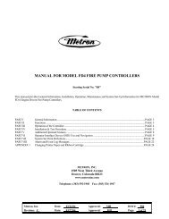
<strong>MANUAL</strong> <strong>FOR</strong> <strong>MODEL</strong> <strong>MP300</strong> <strong>to</strong> <strong>MP700</strong><br />
<strong>ELECTRIC</strong> <strong>MOTOR</strong> DRIVEN<br />
FIRE PUMP CONTROLLERS<br />
Starting Serial No. "MA"<br />
This manual provides General Information, Installation, Operation, Maintenance and System Set-Up Information for METRON Model<br />
Model <strong>MP300</strong> through <strong>MP700</strong> Electric Mo<strong>to</strong>r Driven Fire Pump Controllers.<br />
TABLE OF CONTENTS<br />
PART I General Information........................................................................................................................................PAGE 3<br />
PART II Functions .........................................................................................................................................................PAGE 3<br />
PART III Operation of the Controller.............................................................................................................................PAGE 4<br />
PART IV Installation & Test Procedure .........................................................................................................................PAGE 5<br />
PART V Opera<strong>to</strong>r Interface Device (OID) Use and Navigation ..........................................................................PAGE 8<br />
PART VI System Set Point Definitions........................................................................................................................PAGE 17<br />
PART VII Alarm and Event Log Messages...................................................................................................................PAGE 22<br />
APPENDIX 1 Changing Printer Paper and Ribbon Cartridge ............................................................................................PAGE 24<br />
METRON, INC.<br />
1505 West Third Avenue<br />
Denver, Colorado 80223<br />
www.metroninc.com<br />
Telephone: (303) 592-1903 Fax: (303) 534-1947<br />
Metron, Inc. Date: 09/22/04 Approved: MH DOC#: 605<br />
Revision: C Date: 09/25/06 Approved: MH Page: 1 of 25
THIS PAGE IS BLANK<br />
Page 2 of 25
PART I: GENERAL IN<strong>FOR</strong>MATION<br />
The basic function of the model MP Fire Pump Controller for electric mo<strong>to</strong>r driven fire pumps is <strong>to</strong> au<strong>to</strong>matically start the fire pump<br />
electric mo<strong>to</strong>r upon a drop in pressure in the water main, or from a number of other demand signals. This controller provides alarm<br />
and/or alarm shutdown protection for various mo<strong>to</strong>r and power failures. S<strong>to</strong>pping of the mo<strong>to</strong>r after the demand period is over may<br />
be either manual or au<strong>to</strong>matic. This controller also includes an au<strong>to</strong>matic weekly test starting feature.<br />
PART II: FUNCTIONS<br />
Equipment is provided in the Controller <strong>to</strong> provide the following functions:<br />
A. Au<strong>to</strong>matic Starting From:<br />
a. Drop in water line pressure<br />
b. Operation of optional remote start switches, such as remote start switch, deluge valve switch, fire alarm switch, etc.<br />
c. Weekly test timer<br />
B. OID – Opera<strong>to</strong>r Interface Device - Provided for display of alarm functions, system pressure, 3 phase AC volts, 3 phase mo<strong>to</strong>r<br />
current and alarm conditions, etc. Includes but<strong>to</strong>ns for Au<strong>to</strong>, Test, Manual and Off. Also features a 4 line by 20 character LCD<br />
for display<br />
C. Alarms and Signal Lights - Twelve (12) Standard lights are provided <strong>to</strong> give visual signals for; "Power On”, "System Fault”,<br />
“Phase Failure", "Phase Reversal", “Pump Running”, "Pump Failed <strong>to</strong> Start", "Mo<strong>to</strong>r Overload", "Low Pressure",<br />
"Mo<strong>to</strong>r Lockout", “Local Start”, “Remote Start” and “Deluge Start”. When a transfer switch is supplied, additional lights<br />
are provided for “Transfer Switch in Normal”, “Transfer Switch in Emergency” and “Emergency Iso Sw Open”. In<br />
addition the mode but<strong>to</strong>ns have LED’s on the but<strong>to</strong>n indicating “Au<strong>to</strong>”, Manual”, “Test”, or “Off” mode. 12 additional lights<br />
(9 when a transfer switch is supplied), configurable by the fac<strong>to</strong>ry, are provided for "Pump Room Alarms". An audible alarm<br />
horn is mounted on the front of the cubicle for sounding in the event of failure. Terminals are provided for remote failure<br />
indication of the following:<br />
"Power Available"<br />
"Phase Reversal"<br />
"Pump Running"<br />
"Controller Not in Au<strong>to</strong>"<br />
D. A data logger is provided as standard <strong>to</strong> record system pressure along with numerous alarm conditions and system events. The<br />
data can be displayed on the OID or can be downloaded <strong>to</strong> a PC through the RS232, RS485 or USB port provided on the main<br />
system board or printed <strong>to</strong> the internal printer (if supplied).<br />
E. A weekly test timer is supplied <strong>to</strong> au<strong>to</strong>matically start the pump any set day of the week, at a set time of day, and a preset run<br />
time. See System Config Screen 106.<br />
F. “Start” Push but<strong>to</strong>n – A green push but<strong>to</strong>n is provided on the exterior of the cabinet <strong>to</strong> manually start the pump. When this<br />
but<strong>to</strong>n is pressed, the mo<strong>to</strong>r will continue <strong>to</strong> run until it is s<strong>to</strong>pped using the S<strong>to</strong>p push but<strong>to</strong>n.<br />
G. "S<strong>to</strong>p" Push but<strong>to</strong>n - A red pushbut<strong>to</strong>n is provided on the exterior of the cabinet <strong>to</strong> s<strong>to</strong>p the pump in Au<strong>to</strong>matic only after<br />
starting causes have returned <strong>to</strong> normal. This returns the controller <strong>to</strong> the au<strong>to</strong>matic position. In the Manual mode this will also<br />
s<strong>to</strong>p the pump after starting via the Start push but<strong>to</strong>n.<br />
H. Cabinet - A heavy gauge steel cubicle encloses the controller.<br />
Page 3 of 25
PART III: OPERATION OF THE CONTROLLER<br />
A. When the controller is in the "Au<strong>to</strong>" mode, the main circuit breaker and isolation switch are in the "On" position, the controller<br />
is in standby condition ready <strong>to</strong> start the pump au<strong>to</strong>matically. A green pilot light above the "Au<strong>to</strong>" but<strong>to</strong>n will illuminate in<br />
this mode. Also, the Power On light should be ON indicating that all power is available and the controller is ready <strong>to</strong> start the<br />
pump.<br />
When the water pressure drops below a level, which is set in System Config Screen 101, the Controller will actuate the starting<br />
sequence based on the Model of the controller selected in Screen 301. If the pump fails <strong>to</strong> start after a set time delay (Screen<br />
#103), the "Pump Failed <strong>to</strong> Start" light will illuminate, and the alarm horn will sound. In addition, the "System Fault” light<br />
will illuminate.<br />
The panel is wired so that optional remote start switches may be used, such as Deluge Valve, Remote Start pushbut<strong>to</strong>n, Fire<br />
Alarm switches, etc. The Deluge Valve Switch Option (Screen #124), is a normally closed switch that when opened starts the<br />
pump similar <strong>to</strong> the pressure drop start. In addition, when “Supervisory Power Failure Startup” feature is enabled (System<br />
Config Screen 116), the Controller will au<strong>to</strong>matically start the pump upon loss of a Separate 120VAC Supervisory Power, after<br />
an adjustable time delay (System Config Screen 117).<br />
If the pump s<strong>to</strong>ps while running, and there is still an au<strong>to</strong> start demand, the control will attempt <strong>to</strong> restart the pump. If the pump<br />
fails <strong>to</strong> start the "Pump Failed <strong>to</strong> Start" light will illuminate and the alarm will sound. If, while the pump is operating, the<br />
mo<strong>to</strong>r current exceeds a set overload value (Screen #319), the “Mo<strong>to</strong>r Overload” light will illuminate and the alarm will sound<br />
indicating mo<strong>to</strong>r overload.<br />
The Controller may be configured as either "Manual" or "Au<strong>to</strong>matic" s<strong>to</strong>p as required (System Config Screen 104).<br />
"Manual" s<strong>to</strong>p is set as standard. When Au<strong>to</strong>matic s<strong>to</strong>p is enabled the s<strong>to</strong>p timer is preset at the fac<strong>to</strong>ry <strong>to</strong> 10 minutes. Longer<br />
time settings can be set in System Config screen 105. When “Au<strong>to</strong>matic S<strong>to</strong>p” is disabled, the pump will continue <strong>to</strong> run even<br />
though the pressure switch or other remote starting switch returns <strong>to</strong> its normal position. The pump can be s<strong>to</strong>pped immediately<br />
only by pressing the s<strong>to</strong>p but<strong>to</strong>n or by pressing the Off mode but<strong>to</strong>n. If set up for "Au<strong>to</strong>matic" s<strong>to</strong>p, the pump will be s<strong>to</strong>pped<br />
au<strong>to</strong>matically upon res<strong>to</strong>ration <strong>to</strong> normal of whatever demand switch started the pump providing it has run at least 10 minutes or<br />
longer as set in System Config screen 105. If the demand period was less than the time set on the au<strong>to</strong> s<strong>to</strong>p timer, the pump will<br />
continue <strong>to</strong> run until the timer times out and then will s<strong>to</strong>p.<br />
B. When the "Test" mode but<strong>to</strong>n is pressed for two or more seconds, the pump will be started by causing a drop in water pressure<br />
if the Solenoid Drain Valve Option (Screen #108) is selected. If the Solenoid Drain Valve Option is set <strong>to</strong> NO, the unit will start<br />
au<strong>to</strong>matically similar <strong>to</strong> the Deluge Valve switch start feature. Failure alarm circuits will be operative in the "Test" mode. This<br />
method of starting provides a test of the Controller, thereby assuring proper operation when required. The pump will run<br />
continuously in this position until the "S<strong>to</strong>p" push but<strong>to</strong>n is pressed or the “OFF” mode but<strong>to</strong>n is pressed.<br />
C. Periodic Self Testing - The Weekly Test Start Timer can be set <strong>to</strong> give test runs on any day of the week and time of day desired.<br />
A timing element is incorporated in the controls so that when the pump starts in this manner, it will run for a definite time before<br />
it shuts down. See System Config Screens 109 through 112 <strong>to</strong> set the starting time and length of pump running. See item B.<br />
above. The Weekly test feature will also use the Solenoid Drain Valve option <strong>to</strong> start the pump if it is enabled as described in B.<br />
above. If Screen #113 (S<strong>to</strong>p Mo<strong>to</strong>r During Test on Alarm) is set <strong>to</strong> Yes, the mo<strong>to</strong>r will be s<strong>to</strong>pped should any alarm condition<br />
occur during the weekly test operation.<br />
D. Provision for sequential starting is accomplished by the use of adjustable time delay on pressure drop starting or “Deluge Valve”<br />
starting. On Multiple Pump installations these timers are set sequentially and progressively longer in time <strong>to</strong> prevent more than<br />
one (1) pump from starting simultaneously with another pump. Failure of the lead pump <strong>to</strong> start will not prevent subsequent<br />
pumps from starting. The time delay on starting is set in System Config Screen 103.<br />
E. Emergency Manual Operation: Emergency manual operation is provided in case of failure of control circuitry. This lever is<br />
manually moved <strong>to</strong> the "On" position and must be manually latched in the "ON" position or it will return <strong>to</strong> "Off" when released.<br />
The lever should be moved from the "Off" position <strong>to</strong> the "On" position in as quickly a motion as possible <strong>to</strong> prevent burning the<br />
contacts. The circuit breaker should be turned off <strong>to</strong> disconnect the circuit before releasing emergency lever. This lever is for<br />
emergency use only. A mechanical interlock switch is connected <strong>to</strong> the emergency lever <strong>to</strong> operate the contac<strong>to</strong>r electrically when<br />
all circuitry is functioning properly. This is provided <strong>to</strong> prevent inadvertent slow closing of contac<strong>to</strong>r and burning of contacts.<br />
F. Series MP400 Primary Resistance Start: There are two contac<strong>to</strong>rs supplied along with a set of starting resis<strong>to</strong>rs. The starting<br />
contac<strong>to</strong>r is connected in series with the resis<strong>to</strong>rs <strong>to</strong> reduce the voltage <strong>to</strong> the mo<strong>to</strong>r for a preset time. After this preset time delay<br />
(See Screen #314) the main contac<strong>to</strong>r will close in parallel with the starting contac<strong>to</strong>r and resis<strong>to</strong>rs and thus apply full voltage <strong>to</strong><br />
the mo<strong>to</strong>r. If the mo<strong>to</strong>r is not connected for this test, there will be no voltage drop across the resis<strong>to</strong>rs and full voltage will appear<br />
at the output terminals of the contac<strong>to</strong>rs as soon as the starting contac<strong>to</strong>r closes.<br />
Page 4 of 25
G. Series MP420 Part-Winding Start: There are two contac<strong>to</strong>rs for part-winding start. The start contac<strong>to</strong>r will close immediately<br />
on demand and the other will close after a preset transition time delay (See Screen #314). Full voltage will be present at the output<br />
of both contac<strong>to</strong>rs.<br />
H. Series MP430 Wye-Delta Open Transition: There are three contac<strong>to</strong>rs for wye-delta starting. The start contac<strong>to</strong>r and the<br />
shorting contac<strong>to</strong>r will close immediately on demand. This connects the mo<strong>to</strong>r leads in the wye configuration. After the transition<br />
time delay the shorting contac<strong>to</strong>r opens and the run contac<strong>to</strong>r closes, thus connecting the mo<strong>to</strong>r windings in the delta<br />
configuration. The mo<strong>to</strong>r will now run at full speed and deliver rated horsepower <strong>to</strong> the load.<br />
I. Series MP435 Wye-Delta Closed Transition: The operation of the Series MP435 is almost the same as the Series MP430.<br />
There is an additional resis<strong>to</strong>r contac<strong>to</strong>r and a set of transition resis<strong>to</strong>rs which provides power <strong>to</strong> the mo<strong>to</strong>r windings during<br />
transition from the wye connection <strong>to</strong> the delta connection. After the transition time delay this contac<strong>to</strong>r closes, which connects<br />
the resis<strong>to</strong>rs <strong>to</strong> the mo<strong>to</strong>r windings. After the resis<strong>to</strong>r contac<strong>to</strong>r closes the shorting contac<strong>to</strong>r opens, which in turn allows the run<br />
contac<strong>to</strong>r <strong>to</strong> close, thus connecting the mo<strong>to</strong>r windings in the delta configuration. The mo<strong>to</strong>r will now run at full speed and deliver<br />
rated horsepower <strong>to</strong> the load.<br />
J. Series MP450 Au<strong>to</strong>transformer Start: There are three contac<strong>to</strong>rs for au<strong>to</strong>transformer starting. The start (au<strong>to</strong>transformer)<br />
contac<strong>to</strong>r and the au<strong>to</strong>transformer neutral contac<strong>to</strong>r will close immediately on demand. This connects the mo<strong>to</strong>r leads through the<br />
au<strong>to</strong>transformer <strong>to</strong> reduce the voltage <strong>to</strong> the mo<strong>to</strong>r. After the transition time delay the run contac<strong>to</strong>r closes and then the start<br />
contac<strong>to</strong>r and au<strong>to</strong>transformer neutral contac<strong>to</strong>r open, thus connecting the mo<strong>to</strong>r <strong>to</strong> full voltage. The mo<strong>to</strong>r will now run at full<br />
speed and deliver rated horsepower <strong>to</strong> the load.<br />
K. Series <strong>MP700</strong> Solid State Soft Start: There are two contac<strong>to</strong>rs for solid state soft starting. The solid state starter line contac<strong>to</strong>r<br />
will close immediately on demand and ramp the mo<strong>to</strong>r up <strong>to</strong> speed depending on the solid state starter configuration parameters.<br />
After the transition time delay the run contac<strong>to</strong>r closes and bypasses the solid state starter, thus connecting the mo<strong>to</strong>r <strong>to</strong> full<br />
voltage. The mo<strong>to</strong>r will now run at full speed and deliver rated horsepower <strong>to</strong> the load. When the s<strong>to</strong>p command is received and<br />
the controller is set up for the ramp s<strong>to</strong>p option (Screen #106) the mo<strong>to</strong>r will ramp down in speed over a fixed time delay (Screen<br />
#107) until it s<strong>to</strong>ps.<br />
Note: When using the emergency manual start handle, the soft start unit may display an “OCF” fault condition. This is<br />
normal. The unit is not malfunctioning. When the proper s<strong>to</strong>p sequence is used according <strong>to</strong> paragraph E above, the fault<br />
condition will be cleared and the soft start unit will be ready for a normal start.<br />
PART IV: INSTALLATION AND TEST PROCEDURE<br />
A. INSTALLATION<br />
The Fire Pump Controller has been assembled and wired at the fac<strong>to</strong>ry in accordance with the highest workmanship standards.<br />
All circuits and functions have been thoroughly tested <strong>to</strong> assure correct operation when properly installed. The installer should<br />
be completely familiar with the external hookup of the pump junction box <strong>to</strong> the terminal bar in the Controller. All local electric<br />
codes should be used for proper installation, wiring and grounding of the controller prior <strong>to</strong> startup.<br />
A weekly test drain solenoid valve may be provided <strong>to</strong> relieve water pressure <strong>to</strong> the pressure transducer thus initiating the start<br />
sequence. This test simulates an actual start demand. Since the Controller operates the drain valve only momentarily, a small<br />
amount of water is drained off. The water pressure sensing line <strong>to</strong> the Controller from the pump must be thoroughly flushed<br />
before connection <strong>to</strong> the Controller in order <strong>to</strong> remove chips, particles, or other matter, that could enter the plumbing<br />
components in the Controller.<br />
Controllers configured with "Au<strong>to</strong>matic S<strong>to</strong>p" enabled may be changed <strong>to</strong> "Manual" s<strong>to</strong>p by disabling this feature in System<br />
Config Screen 104. If deluge valve switches are <strong>to</strong> be used for starting, enable the Deluge Valve Option in Config Screen 121<br />
and connect the remote normally closed switch <strong>to</strong> terminals 74 and 111.<br />
B. TEST PROCEDURE<br />
All of the following tests should be made on each unit after installation. If each test is satisfac<strong>to</strong>ry, the opera<strong>to</strong>r may place the<br />
control switch in "Au<strong>to</strong>" mode and depend upon the panel operating properly when required. Also, any one or all of these tests<br />
may be carried out at any time after installation, if so desired. NOTE: If the Supervisory Power Failure Start Option has<br />
been Enabled (Screen #116) and 115 Volts A.C. is not connected <strong>to</strong> Controller, the "System Fault" light will illuminate<br />
and the controller will start au<strong>to</strong>matically after a time delay. The 115VAC must be turned on <strong>to</strong> prevent the pump from<br />
starting.<br />
Phase Reversal Alarm – Upon initial power up, if a phase reversal alarm should sound, the following process can be used <strong>to</strong><br />
correct the alarm. If a test of the mo<strong>to</strong>r rotation indicates that the mo<strong>to</strong>r is turning opposite of the correct direction, the mo<strong>to</strong>r<br />
Page 5 of 25
mo<strong>to</strong>r leads must be reversed <strong>to</strong> cure the condition. Turn the controller circuit breaker and isolation switch off and verify that<br />
incoming power on the load side of the controller isolation switch has been disconnected. Then reverse any two of the mo<strong>to</strong>r<br />
leads. If there are multiples sets of mo<strong>to</strong>r leads, i.e. Part Winding start or Wye-Delta start, then both sets of leads must be<br />
reversed. Be certain <strong>to</strong> change the same set of wires at the two contac<strong>to</strong>rs. Then turn the controller isolation switch and circuit<br />
breaker back on and check for correct rotation of the mo<strong>to</strong>r and then follow the procedure below <strong>to</strong> correct the Phase Reversal<br />
alarm.<br />
If the mo<strong>to</strong>r is turning the correct direction but there is a Phase Reversal alarm then this can be corrected as follows. Press the<br />
Config but<strong>to</strong>n on the front of the OID. Press the Config (2) but<strong>to</strong>n again <strong>to</strong> access the User Preferences Setup screens. Press the<br />
Up arrow key once. The OID should then read “223 User Preferences – Reversed Phase”. Press the Change/Enter but<strong>to</strong>n. The<br />
system will then ask for a password. Enter 1111 and then press enter. Press the Up or Down arrow key <strong>to</strong> change the setting in<br />
the lower left hand corner of the screen from “No” <strong>to</strong> “Yes” then press the Change/Enter but<strong>to</strong>n. After a few seconds the “Phase<br />
Reversal” LED will reset. Also, press the Silence\ Reset but<strong>to</strong>n for approx. 3 seconds <strong>to</strong> silence the audible alarm.<br />
INPUT/OUTPUT STATUS INDICATOR LIGHTS<br />
Light Emitting Diodes (L.E.D.) lights have been installed on the microprocessor module <strong>to</strong> indicate the status of each input and<br />
output terminal. Status indication for the standard functions is given below:<br />
Terminal Number<br />
L.E.D. (light) "ON" Indication<br />
(Microprocessor Func #)<br />
(Out 02)<br />
Circuit Breaker Shunt Trip<br />
(Out 03)<br />
Start Contac<strong>to</strong>r relay (if applicable)<br />
(Out 04)<br />
Run Contac<strong>to</strong>r relay<br />
(Out 05)<br />
Start signal <strong>to</strong> Soft Start (Model <strong>MP700</strong> only)<br />
(Out 06)<br />
Power <strong>to</strong> Soft Start (Model <strong>MP700</strong> only)<br />
(In 01)<br />
Emergency Start lever activated<br />
(In 02)<br />
Start Pushbut<strong>to</strong>n<br />
(In 03)<br />
S<strong>to</strong>p Pushbut<strong>to</strong>n<br />
(In 04)<br />
Start Contac<strong>to</strong>r closed<br />
(In 05)<br />
Run Contac<strong>to</strong>r closed<br />
(In 06)<br />
Transfer Switch position (if applicable)<br />
(In 07)<br />
Transfer Switch ready <strong>to</strong> transfer (if applicable)<br />
(In 08)<br />
Transfer Switch Emergency Iso Switch Open (if applicable)<br />
a. AUTOMATIC STARTING TESTS:<br />
1. Place control in "Au<strong>to</strong>" position.<br />
2. Bleed off pressure in system until pressure drops below the low set point.<br />
3. Pump should start au<strong>to</strong>matically and continue <strong>to</strong> run after pressure rises above the high set point, if arranged for<br />
"Manual" s<strong>to</strong>p. If arranged for "Au<strong>to</strong>matic" s<strong>to</strong>p, pump will continue <strong>to</strong> run for time set on Au<strong>to</strong> S<strong>to</strong>p Timer and<br />
then s<strong>to</strong>p.<br />
4. Press the "S<strong>to</strong>p" push but<strong>to</strong>n <strong>to</strong> s<strong>to</strong>p the pump.<br />
5. Repeat tests for each demand switch such as deluge valve (if enabled), remote start, etc.<br />
b. PERIODIC WEEKLY START TEST:<br />
1. Pressure must be up and all other demand switches de-activated.<br />
2. When the current day and time of day matches the settings in System Config screens 107 and 108, the solenoid drain<br />
valve will energize (if enabled and supplied, see screen #108) and the pump will start. It will continue <strong>to</strong> run for the<br />
amount of time set and then s<strong>to</strong>p au<strong>to</strong>matically.<br />
c. SETTING PROGRAM WEEKLY TEST TIME: System Config screen 109 through 112.<br />
d. REMOTE START SWITCH CIRCUITS: Field wiring terminals are provided on the controller so that optional remote<br />
start switches such as Remote Pushbut<strong>to</strong>n Stations, Deluge Valve Switch, Fire Alarm Switches, etc., may be used <strong>to</strong> start the<br />
pump. Two (2) sets of terminals are provided. Terminals #112 and #31 are used for remote manual start push but<strong>to</strong>ns (close<br />
<strong>to</strong> start). Terminals #111 and #31 are used for remote Deluge Valve Switch or other remote au<strong>to</strong>matic start switches (open <strong>to</strong><br />
Page 6 of 25
start). Upon au<strong>to</strong>matic start from this type of switch, the pump will be s<strong>to</strong>pped either au<strong>to</strong>matically after the demand switch<br />
de-activates and Pump Au<strong>to</strong> S<strong>to</strong>p Timer times out, or manually at the Controller. Terminals #111 and #31 must have a<br />
jumper installed if a remote Deluge switch is “Enabled” but not <strong>to</strong> be used. When the controller is shipped from the fac<strong>to</strong>ry<br />
Deluge Valve start is Disabled (System Config screen 121).<br />
e. AC POWER FAILURE STARTING: If this feature has been enabled it can be tested by disconnecting the supervisory<br />
power 115 V.A.C. <strong>to</strong> the Controller. After the preset time delay (which is specified in System Config screen 112), the<br />
Controller will commence starting of the pump. The "System Fault" LED will illuminate and the alarm will sound.<br />
f. NORMAL OPERATION – AUTOMATIC: Press "Au<strong>to</strong>" mode but<strong>to</strong>n on OID. A green "Au<strong>to</strong>matic Mode" light will<br />
illuminate and the pump will au<strong>to</strong>matically start upon drop in pressure or operation of other start switches. If the Au<strong>to</strong> S<strong>to</strong>p<br />
Timer is disabled (Manual S<strong>to</strong>p) the pump must be turned off at the Controller. When the Au<strong>to</strong> S<strong>to</strong>p Timer is enabled, upon<br />
termination of the demand signal, the pump will run for the length of time left on the Au<strong>to</strong> S<strong>to</strong>p Timer and then will s<strong>to</strong>p<br />
au<strong>to</strong>matically.<br />
g. AN ADJUSTABLE SEQUENTIAL START TIMER IS SUPPLIED <strong>FOR</strong> MULTIPLE PUMP INSTALLATION:<br />
Normally, the leading pump Controller will not have a delay timer and will commence starting of the pump immediately<br />
upon operation of a demand signal (other than Power Failure which is time delayed). The subsequent Controllers will have a<br />
time delay which is adjustable from 0 <strong>to</strong> 999 seconds. Each time delay should be set with progressively longer times on each<br />
subsequent pump. The recommended time interval is ten (10) <strong>to</strong> fifteen (15) seconds. This may be extended or shortened as<br />
required by the local authorities having jurisdiction.<br />
h. PUMP ROOM ALARMS: Field terminals may be provided for various inputs from pump room alarms. These alarms<br />
include: Low Pump Room Temperature, Reservoir Low, Reservoir Empty, Low Suction Pressure, Relief Valve Discharge<br />
and/or Flow Meter On etc. A maximum of twelve (12) (or nine (9) if a transfer switch is supplied), pump room alarms is<br />
available. Each auxiliary alarm is configurable so that the alarm horn may or may not sound and the light will come on when<br />
the alarm sensor contacts close. These pump room alarms can be silenced with the “Silence” push but<strong>to</strong>n on the OID if they<br />
have been configured as silenceable.<br />
Page 7 of 25
PART V: OPERATOR INTERFACE DEVICE (OID) USE AND NAVIGATION<br />
The Opera<strong>to</strong>r Interface Device (OID) provides visual indication of the alarms, status of system parameters, and an interface <strong>to</strong><br />
change set points <strong>to</strong> configure the controller <strong>to</strong> operate appropriately for various installation requirements.<br />
Labeled LED<br />
Annuncia<strong>to</strong>r<br />
Common Tasks Performed Using The OID<br />
Silencing Horn: If a horn is sounding and the alarm is silenceable, a quick<br />
press of the [SILENCE/RESET/ESC] will silence the horn (less than 1<br />
second press).<br />
Resetting Alarms: If the alarm condition has cleared, press and hold the<br />
[SILENCE/RESET/ESC] but<strong>to</strong>n 2 <strong>to</strong> 5 seconds <strong>to</strong> reset alarms.<br />
Operating Mode Change: The operational mode that the controller is in can<br />
be changed by pressing the [AUTO] [<strong>MANUAL</strong>] or [OFF] but<strong>to</strong>ns. An LED<br />
will illuminate on the appropriate but<strong>to</strong>n indicating the mode of operation the<br />
controller is in.<br />
Test Mode: When controller is in Au<strong>to</strong> Mode, pressing and holding the<br />
[TEST] but<strong>to</strong>n for two or more seconds will open the pressure drain solenoid<br />
thus dropping the pressure, which causes the controller <strong>to</strong> start the pump.<br />
Pressing and releasing the [TEST] but<strong>to</strong>n in Manual Mode directly controls<br />
the opening and closing of the drain solenoid. The pump will not<br />
au<strong>to</strong>matically start when in Manual Mode.<br />
Lamp Test: To illuminate and check all the OID LED’s and the horn, press<br />
and hold the [SILENCE/RESET/ESC] but<strong>to</strong>n 5 or more seconds or until all<br />
the lights turn on.<br />
System Operation and<br />
Control Type But<strong>to</strong>ns<br />
Digital Display With<br />
Navigation But<strong>to</strong>ns<br />
Page 8 of 25
OID Screen Map<br />
METRON OID100<br />
POWER<br />
1<br />
2<br />
3<br />
SYSTEM<br />
STATUS<br />
SYSTEM<br />
LOGS<br />
CONFIG<br />
PRINT<br />
CHANGE/<br />
ENTER<br />
AUTO <strong>MANUAL</strong> TEST<br />
OFF<br />
SILENCE/<br />
RESET/<br />
ESC<br />
1 SYSTEM STATUS B1<br />
PRES STRT AB 460V<br />
110 100 BC 461V<br />
psi psi AC 460V<br />
SYSTEM LOGS<br />
1) Alarm Log<br />
2) Event Log<br />
3) Pressure Log<br />
1 CONFIG<br />
1) SYSTEM SETPOINTS<br />
2) USER PREFERENCES<br />
3) TECH SCREENS<br />
2 SYSTEM STATUS<br />
Phase A 125 Amps<br />
Phase B 124 Amps<br />
Phase C 125 Amps<br />
2 CONFIG<br />
1) ANALOG SIGNALS<br />
2) AUXILLIARY ALARMS<br />
3 SYSTEM STATUS<br />
Pump Countdown Tmr<br />
0min Until Start<br />
0min Until S<strong>to</strong>p<br />
4 SYSTEM STATUS<br />
Pump run Hr 0.0<br />
# of Starts 0<br />
Fri12/15/05 09:51:38<br />
5 SYSTEM STATUS<br />
Controller Power<br />
On Time: 18.5 Hrs<br />
Mon10/20/04 17:53:26<br />
# 1 ALARM LOG<br />
Pump Failed To<br />
Start Alarm Occurred<br />
10/16/04 07:32:15<br />
# 1 ALARM DETAILS<br />
Pump Failed To<br />
Start Alarm Occurred<br />
10/16/04 07:32:15<br />
# 1 ALARM DETAILS<br />
Pressure: 83.2psi<br />
System Au<strong>to</strong>:Yes<br />
Pump Running:No<br />
# 1 EVENT LOG<br />
System in Off<br />
Mode Occurred<br />
10/16/04 13:15:15<br />
# 1 EVENT DETAILS<br />
System in Off<br />
Mode Occurred<br />
10/16/04 13:15:15<br />
# 1 EVENT DETAILS<br />
Pressure: 83.2psi<br />
System Au<strong>to</strong>:Yes<br />
Pump Running:No<br />
PRESSURE LOG<br />
10/16/04 17:52:45<br />
112 psi<br />
Skip Rate:[EACH ]<br />
PRESSURE LOG<br />
10/16/04 17:52:30<br />
112 psi<br />
Skip Rate:[EACH ]<br />
PRESSURE LOG<br />
10/16/04 17:52:15<br />
113 psi<br />
Skip Rate:[EACH ]<br />
Continued on next<br />
page.<br />
6 SYSTEM STATUS<br />
Firmware Ver SV 1.1<br />
Commissioned Date:<br />
10/15/04<br />
# 1 ALARM DETAILS<br />
Phase A Amps 0<br />
Phase B Amps 0<br />
Phase C Amps 0<br />
# 1 EVENT DETAILS<br />
Phase A Amps 0<br />
Phase B Amps 0<br />
Phase C Amps 0<br />
| |<br />
| |<br />
| |<br />
# 1 ALARM DETAILS<br />
Phase AB Volt 460<br />
Phase BC Volt 461<br />
Phase AC Volt 464<br />
# 1 EVENT DETAILS<br />
Phase AB Volt 460<br />
Phase BC Volt 461<br />
Phase AC Volt 464<br />
# 2 ALARM LOG<br />
Supvr Power Failure<br />
Alarm Cleared<br />
10/16/04 07:09:48<br />
# 2 EVENT LOG<br />
Pump Failed To<br />
Start Alarm Occurred<br />
10/16/04 07:32:15<br />
# 3 ALARM LOG<br />
Mo<strong>to</strong>r Overload<br />
Alarm Occurred<br />
10/16/04 06:49:03<br />
# 3 EVENT LOG<br />
Supvr Power Failure<br />
Alarm Cleared<br />
10/16/04 07:09:48<br />
| |<br />
| |<br />
| |<br />
| |<br />
| |<br />
| |<br />
Page 9 of 25
OID Screen Map (continued)<br />
1 CONFIG<br />
1) SYSTEM SETPOINTS<br />
2) USER PREFERENCES<br />
3) TECH SCREENS<br />
2 CONFIG<br />
1) ANALOG SIGNALS<br />
2) AUXILLIARY ALARMS<br />
101 SYSTEM SETPOINTS<br />
Pump Start<br />
Pressure<br />
[100.0]psi 0-999.9<br />
201 USER PREFERENCES<br />
Set System Real<br />
Time Clock<br />
[17:03:52]<br />
301 TECH SCREENS<br />
Controller Model<br />
Number<br />
[ <strong>MP300</strong>]<br />
400 ANALOG SIGNALS<br />
Analog Input 01<br />
Slope:<br />
[0.2135678]<br />
501 AUX USER PROGRAM<br />
AUX# 1<br />
Enabled<br />
[Yes]<br />
102 SYSTEM SETPOINTS<br />
Pump S<strong>to</strong>p<br />
Pressure<br />
[110.0]psi 0-999.9<br />
202 USER PREFERENCES<br />
Set System Date<br />
[02/16/03]<br />
302 TECH SCREENS<br />
Transfer Switch<br />
Supplied<br />
[Yes]<br />
401 ANALOG SIGNALS<br />
Analog Input 01<br />
Offset:<br />
[- 75.2568]<br />
502 AUX USER PROGRAM<br />
AUX# 1<br />
Input Number<br />
[30] 0-40<br />
103 SYSTEM SETPOINTS<br />
Pump Start<br />
Delay Time<br />
[ 10] seconds 0-999<br />
203 USER PREFERENCES<br />
Set System Day<br />
Of The Week<br />
[Sun]<br />
303 TECH SCREENS<br />
Nominal System<br />
Voltage<br />
[480]VAC 120-7200<br />
402 ANALOG SIGNALS<br />
Analog Input 1 651<br />
Minimum Counts<br />
[ 200]<br />
503 AUX USER PROGRAM<br />
AUX# 1<br />
Input Contact Type<br />
[NO ]<br />
104 SYSTEM SETPOINTS<br />
Pump Au<strong>to</strong>matic<br />
S<strong>to</strong>p Enabled<br />
[Yes]<br />
204 USER PREFERENCES<br />
Log System Pressure<br />
Drop Events<br />
[Yes]<br />
304 TECH SCREENS<br />
CPT Primary Voltage<br />
Rating<br />
[ 480] 120-7200<br />
403 ANALOG SIGNALS<br />
Analog Input 01 651<br />
Maximum Counts<br />
[ 800]<br />
504 AUX USER PROGRAM<br />
AUX# 1<br />
Trip Time<br />
[ 0]sec 0-999<br />
105 SYSTEM SETPOINTS<br />
Pump Minimum<br />
Run Time<br />
[30]minutes 30-99<br />
205 USER PREFERENCES<br />
Low Pressure Event<br />
Trip Pressure<br />
[5]psi 0-999.9<br />
305 TECH SCREENS<br />
Current Transformer<br />
Ratio<br />
[1200] /5 1-9999<br />
404 ANALOG SIGNALS<br />
Analog Input 1 651<br />
Minimum PSI<br />
[ 3] 0-10<br />
505 AUX USER PROGRAM<br />
AUX# 1<br />
Reset Time<br />
[ 0]sec 0-999<br />
106 SYSTEM SETPOINTS<br />
Ramp S<strong>to</strong>p Option<br />
<strong>MP700</strong><br />
[Yes]<br />
206 USER PREFERENCES<br />
System Pressure Drop<br />
Event Time Span<br />
[15] seconds 0-20<br />
306 TECH SCREENS<br />
Restart Time<br />
Delay<br />
[ 3]sec 0-99<br />
405 ANALOG SIGNALS<br />
Analog Input 02<br />
Slope<br />
[ 0.0094996]<br />
506 AUX USER PROGRAM<br />
AUX# 1<br />
Au<strong>to</strong> Reset Enabled<br />
[Yes]<br />
107 SYSTEM SETPOINTS<br />
Ramp S<strong>to</strong>p Option<br />
Time<br />
[10]sec 1-99<br />
207 USER PREFERENCES<br />
Time Between<br />
Pressure Log Samples<br />
[ 15] seconds 15-999<br />
307 TECH SCREENS<br />
Mo<strong>to</strong>r Full Load<br />
Amps<br />
[ 124]Amps 0-999<br />
406 ANALOG SIGNALS<br />
Analog Input 02<br />
Offset<br />
[-75.2568]<br />
507 AUX USER PROGRAM<br />
AUX# 1<br />
Horn Enabled<br />
[No ]<br />
108 SYSTEM SETPOINTS<br />
Solenoid Drain<br />
Valve Option<br />
[Yes]<br />
208 USER PREFERENCES<br />
Au<strong>to</strong> Print Each<br />
Pressure Log Sample<br />
[No ]<br />
308 TECH SCREENS<br />
Low Voltage<br />
Trip Percent<br />
[85]% 50-99<br />
407 ANALOG SIGNALS<br />
Analog Input 02 651<br />
Minimum Counts<br />
[ 0]<br />
508 AUX USER PROGRAM<br />
AUX# 1<br />
Horn Silence<br />
[No ]<br />
109 SYSTEM SETPOINTS<br />
Au<strong>to</strong>matic Weekly<br />
Test Run<br />
[Yes]<br />
209 USER PREFERENCES<br />
Au<strong>to</strong> Print Each<br />
Event Log Entry<br />
[No ]<br />
309 TECH SCREENS<br />
Low Voltage<br />
Time Delay<br />
[ 5]sec 0-99<br />
408 ANALOG SIGNALS<br />
Analog Input 03<br />
Slope<br />
[0.0094996]<br />
509 AUX USER PROGRAM<br />
AUX# 1<br />
LED Number<br />
[ 0] 0-24<br />
110 SYSTEM SETPOINTS<br />
Au<strong>to</strong> Weekly Test<br />
Day Of The Week<br />
[Mon]<br />
210 USER PREFERENCES<br />
Selective Range<br />
Printing<br />
[ 1] Before 1-99<br />
310 TECH SCREENS<br />
High Voltage Alarm<br />
% of Nominal<br />
[125]% 0-999<br />
409 ANALOG SIGNALS<br />
Analog Input 03<br />
Offset<br />
[-75.2568]<br />
510 AUX USER PROGRAM<br />
AUX# 1<br />
Output1 Number<br />
[ 0] 0-19<br />
111 SYSTEM SETPOINTS<br />
Au<strong>to</strong> Weekly Pump<br />
Test Start Time<br />
[10:00:00]<br />
211 USER PREFERENCES<br />
Selective Range<br />
Printing<br />
[ 1] After 1-99<br />
311 TECH SCREENS<br />
High Voltage<br />
Time Delay<br />
[ 5]sec 0-99<br />
410 ANALOG SIGNALS<br />
Analog Input 03<br />
Minimum Counts<br />
[ 0]<br />
511 AUX USER PROGRAM<br />
AUX# 1<br />
Output2 Number<br />
[ 0] 0-19<br />
112 SYSTEM SETPOINTS<br />
Au<strong>to</strong> Weekly Test<br />
Length Of Run Time<br />
[30] minutes 30-99<br />
212 USER PREFERENCES<br />
High Discharge Press<br />
Alarm Option<br />
[ No]<br />
312 TECH SCREENS<br />
Phase Loss % of<br />
Nominal Voltage<br />
[70]% 0-99<br />
411 ANALOG SIGNALS<br />
Minimum Volts<br />
[10] 0-9999<br />
512 AUX USER PROGRAM<br />
AUX# 1<br />
Output3 Number<br />
[ 0] 0-19<br />
113 SYSTEM SETPOINTS<br />
S<strong>to</strong>p Mo<strong>to</strong>r during<br />
Test on Alarm<br />
[No]<br />
213 USER PREFERENCES<br />
High Discharge<br />
Alarm Pressure<br />
[100] 1-999<br />
313 TECH SCREENS<br />
Phase Loss<br />
Time Delay<br />
[5]sec 0-99<br />
412 ANALOG SIGNALS<br />
Phase AB Voltage<br />
Slope:<br />
[0.729750]<br />
513 AUX USER PROGRAM<br />
AUX# 1<br />
Record In Event Log<br />
[No ]<br />
114 SYSTEM SETPOINTS<br />
Supervisory Power<br />
Option<br />
[No]<br />
214 USER PREFERENCES<br />
High Discharge Alarm<br />
Time Delay<br />
[ 8]sec 0-99<br />
314 TECH SCREENS<br />
Start Transition<br />
Time Delay<br />
[ 2]sec 0-10<br />
413 ANALOG SIGNALS<br />
Phase AB Voltage<br />
Offset:<br />
[6.52430]<br />
514 AUX USER PROGRAM<br />
AUX# 1<br />
Record In Alarm Log<br />
[No ]<br />
115 SYSTEM SETPOINTS<br />
Supervisory Power<br />
Delay Time<br />
[ 2] sec 0-99<br />
215 USER PREFERENCES<br />
Low Discharge Press<br />
Alarm Option<br />
[ No]<br />
315 TECH SCREENS<br />
Single Phase Alarm<br />
% of FLA<br />
[ 5]% 0-99<br />
414 ANALOG SIGNALS<br />
Phase BC Voltage<br />
Slope:<br />
[0.729750]<br />
515 AUX USER PROGRAM<br />
AUX# 1<br />
Text Message Number<br />
[ 0] 0-27<br />
Page 10 of 25
116 SYSTEM SETPOINTS<br />
Supervisory Power<br />
Failure Startup<br />
[Yes]<br />
216 USER PREFERENCES<br />
Low Discharge<br />
Alarm Pressure<br />
[100] 0-999<br />
316 TECH SCREENS<br />
Single Phase Loss<br />
Time Delay<br />
[5]seconds 0-99<br />
415 ANALOG SIGNALS<br />
Phase BC Voltage<br />
Offset:<br />
[6.52430]<br />
117 SYSTEM SETPOINTS<br />
Supvervisory Power<br />
Fail Start Dly Time<br />
[ 1]minutes 0-500<br />
217 USER PREFERENCES<br />
Low Discharge Alarm<br />
Time Delay<br />
[ 8]sec 0-99<br />
317 TECH SCREENS<br />
Mo<strong>to</strong>r Run % of<br />
FLA<br />
[20]% 0-99<br />
416 ANALOG SIGNALS<br />
Phase AC Voltage<br />
Slope:<br />
[0.729750]<br />
118 SYSTEM SETPOINTS<br />
Pressure Transducer<br />
Failure Pump Start<br />
[ No]<br />
218 USER PREFERENCES<br />
No Load Amps %<br />
of FLA<br />
[ 5] 0-99<br />
318 TECH SCREENS<br />
Use Mo<strong>to</strong>r Current<br />
for Pump Running Sig<br />
[Yes]<br />
417 ANALOG SIGNALS<br />
Phase AC Voltage<br />
Offset:<br />
[6.52430]<br />
119 SYSTEM SETPOINTS<br />
Shutdown On Low<br />
Intake Pressure/Lvl<br />
[No ]<br />
219 USER PREFERENCES<br />
No Load Time<br />
Time Delay<br />
[ 8]sec 0-99<br />
319 TECH SCREENS<br />
Overload Alarm<br />
% of FLA<br />
[125]% 100-199<br />
418 ANALOG SIGNALS<br />
Minimum Amps<br />
[10] 0-9999<br />
120 SYSTEM SETPOINTS<br />
Shutdown On Low<br />
Intake Trip Time<br />
[ 0]seconds 0-999<br />
220 USER PREFERENCES<br />
LCD Back Light Mode<br />
0=Always on<br />
[0]] 1=Power Save<br />
320 TECH SCREENS<br />
Overload Alarm<br />
Time Delay<br />
[3]sec 0-99<br />
419 ANALOG SIGNALS<br />
Phase A Amps<br />
Slope:<br />
[ 2.9635]<br />
121 SYSTEM SETPOINTS<br />
Low Intake Shutdown<br />
Au<strong>to</strong> Reset<br />
[ No]<br />
221 USER PREFERENCES<br />
Language Select<br />
[English]<br />
321 TECH SCREENS<br />
Start on Single<br />
Phase Loss<br />
[Yes]<br />
420 ANALOG SIGNALS<br />
Phase A Amps<br />
Offset:<br />
[36.9270]<br />
122 SYSTEM SETPOINTS<br />
Low Intake Shutdown<br />
Au<strong>to</strong> Reset Time<br />
[ 0]seconds 0-999<br />
222 USER PREFERENCES<br />
Change User Password<br />
Level 1<br />
[****]<br />
322 TECH SCREENS<br />
Mo<strong>to</strong>r Run Amps<br />
Time Delay<br />
[5]sec 0-99<br />
421 ANALOG SIGNALS<br />
Phase B Amps<br />
Slope:<br />
[ 2.9635]<br />
123 SYSTEM SETPOINTS<br />
Pressure Switch<br />
Pump Start<br />
[No ]<br />
223 USER PREFERENCES<br />
Reversed Phase<br />
order (1-3-2)<br />
[No]<br />
323 TECH SCREENS<br />
Mo<strong>to</strong>r Start<br />
Time Delay<br />
[10]sec 0-99<br />
422 ANALOG SIGNALS<br />
Phase B Amps<br />
Offset:<br />
[36.9270]<br />
124 SYSTEM SETPOINTS<br />
Deluge Valve<br />
Pump Start<br />
[No]<br />
324 TECH SCREENS<br />
Under Frequency<br />
% of Nominal<br />
[25] 0-99<br />
423 ANALOG SIGNALS<br />
Phase C Amps<br />
Slope:<br />
[ 2.9635]<br />
325 TECH SCREENS<br />
Under Frequency<br />
Time Delay<br />
[5]sec 0-99<br />
424 ANALOG SIGNALS<br />
Phase C Amps<br />
Offset:<br />
[36.9270]<br />
326 TECH SCREENS<br />
Over Frequency<br />
% of Nominal<br />
[25]% 0-999<br />
ANALOG INPUT COUNTS<br />
649 1176 1221 0<br />
0 0 0 0<br />
0 0<br />
327 TECH SCREENS<br />
Over Frequency<br />
Time Delay<br />
[5]sec 0-99<br />
Daughter board<br />
counts<br />
649 1176 1221 0<br />
0 0 0 0<br />
328 TECH SCREENS<br />
Alarm log 31/2<br />
Event log 50/ 4<br />
Pr. log 0/29333<br />
425 ANALOG SIGNALS<br />
Set Volts/Amps Slope<br />
Offset <strong>to</strong> Fact<br />
Dflt[Yes]<br />
329 TECH SCREENS<br />
System Commissioned<br />
Date<br />
[00/00/00]<br />
330 TECH SCREENS<br />
Change Tech Password<br />
[******]<br />
331 TECH SCREENS<br />
Password Logout<br />
Time<br />
[5]min 1-15<br />
Page 11 of 25
The [SYSTEM STATUS], [SYSTEM LOGS], and [CONFIG] but<strong>to</strong>ns navigate the user <strong>to</strong> the <strong>to</strong>p screen of a column of similarly<br />
grouped screens or menus.<br />
SYSTEM STATUS: The [SYSTEM STATUS] but<strong>to</strong>n can be pressed at any time <strong>to</strong> return the screen <strong>to</strong> the home System Status<br />
screen #1. System Status screens display the real time information variables about the pump system.<br />
SYSTEM LOGS: The [SYSTEM LOGS] but<strong>to</strong>n displays the System Logs menu. Once the menu is displayed, but<strong>to</strong>ns with<br />
numbers on them can be used <strong>to</strong> enter the selected data log. See the following page for details on navigating the System<br />
Logs.<br />
CONFIGURATION: The [CONFIG] but<strong>to</strong>n displays the Config menu which groups the different types of set points that<br />
configure the system <strong>to</strong> operate in the desired manner. Use the [UP] and [DOWN] but<strong>to</strong>ns <strong>to</strong> scroll between the two menu<br />
screens. But<strong>to</strong>ns with numbers on them can be used <strong>to</strong> enter the selected configuration screen group. See the System<br />
Setpoint Definitions section for descriptions on the functionality of each set point.<br />
1 SYSTEM STATUS B1<br />
PRES STRT AB 460V<br />
110 100 BC 461V<br />
psi psi AC 460V<br />
2 SYSTEM STATUS<br />
Phase A 125 Amps<br />
Phase B 124 Amps<br />
Phase C 125 Amps<br />
3 SYSTEM STATUS<br />
Pump Countdown Tmr<br />
0sec Until Start<br />
0min Until S<strong>to</strong>p<br />
4 SYSTEM STATUS<br />
Pump Run Hrs: 5.3<br />
# Of Starts: 8<br />
Mon 10/17/04 17:53:26<br />
5 SYSTEM STATUS<br />
Controller Power<br />
On Time 18.5 Hrs<br />
10/15/04 17:53:26<br />
6 SYSTEM STATUS<br />
Firmware Ver SV 1.1<br />
Commissioned Date:<br />
11/15/02<br />
SYSTEM LOGS<br />
1) Alarm Log<br />
2) Event Log<br />
3) Pressure Log<br />
# 1 ALARM LOG<br />
Pump Failed To<br />
Start Alarm Occurred<br />
20/16/04 07:32:15<br />
# 1 EVENT LOG<br />
System in Off<br />
Mode Occurred<br />
10/16/04 13:15:15<br />
PRESSURE LOG<br />
10/16/04 17:52:45<br />
112 psi<br />
Skip Rate:[EACH ]<br />
See the following page for an example of<br />
scrolling through the Alarm, Event, and<br />
Pressure Logs<br />
1 CONFIG<br />
1) SYSTEM SETPOINTS<br />
2) USER PREFERENCES<br />
3) TECH SCREENS<br />
2 CONFIG<br />
1) ANALOG SIGNALS<br />
2) AUXILLIARY ALARMS<br />
3) COMM PORTS<br />
101 SYSTEM SETPOINTS<br />
Pump Start<br />
Pressure<br />
[100.0]psi 0-999.9<br />
201 USER PREFERENCES<br />
Set System Real<br />
Time Clock<br />
[17:03:52]<br />
301 TECH SCREENS<br />
Controller Model<br />
Number<br />
[<strong>MP300</strong>]<br />
401 ANALOG SIGNALS<br />
Analog Input 01<br />
Slope:<br />
[0.21346771]<br />
501 AUX USER PROGRAMS<br />
AUX# 1<br />
Enabled<br />
[Yes]<br />
Page 12 of 25
SYSTEM LOGS: The Model MP Electric controller has three separate data logs; 1) alarm log, 2) event log, and 3) pressure log.<br />
The alarm log is a subset of the event log and only displays the last ten alarms that have occurred or cleared. The event log<br />
records all alarm and system function type events<br />
SYSTEM LOGS<br />
1) Alarm Log<br />
2) Event Log<br />
3) Pressure Log<br />
SYSTEM LOGS: The [UP] and [DOWN] arrow but<strong>to</strong>ns can be used <strong>to</strong> scroll through the<br />
three data logs. The [CHANGE/ENTER] but<strong>to</strong>n enters and exits the alarm/event details in<br />
either the Alarm or Event logs. In the Pressure Log the [CHANGE/ENTER] but<strong>to</strong>n changes<br />
the skip rate used <strong>to</strong> scroll through the logged pressure readings.<br />
# 1 ALARM LOG<br />
Pump Failed To<br />
Start Alarm Occurred<br />
10/16/04 07:32:15<br />
# 1 ALARM DETAILS<br />
Pump Failed To<br />
Start Alarm Occurred<br />
10/16/04 07:32:15<br />
# 1 ALARM DETAILS<br />
AB V 460 A 32<br />
BC V 461 B 32<br />
AC V 460 C 33<br />
# 1 ALARM DETAILS<br />
Pump Running: Yes<br />
# 1 EVENT LOG<br />
System in Off<br />
Mode Occurred<br />
10/16/04 13:15:15<br />
# 1 EVENT DETAILS<br />
System in Off<br />
Mode Occurred<br />
10/16/04 13:15:15<br />
# 1 EVENT DETAILS<br />
AB V 460 A 32<br />
BC V 461 B 32<br />
AC V 460 C 33<br />
# 1 EVENT DETAILS<br />
Pump Running: Yes<br />
PRESSURE LOG<br />
10/16/04 17:52:45<br />
112 psi<br />
Skip Rate:[EACH ]<br />
PRESSURE LOG<br />
10/16/04 17:52:30<br />
112 psi<br />
Skip Rate:[EACH ]<br />
PRESSURE LOG<br />
10/16/04 17:52:15<br />
113 psi<br />
Skip Rate:[EACH ]<br />
# 2 ALARM LOG<br />
Superv Power Failure<br />
Alarm Cleared<br />
10/16/04 07:09:48<br />
# 3 ALARM LOG<br />
Superv Power Failure<br />
Alarm Occurred<br />
10/16/04 06:49:03<br />
# 2 EVENT LOG<br />
Pump Failed To<br />
Start Alarm Occurred<br />
10/16/04 07:32:15<br />
# 3 EVENT LOG<br />
Superv Power Failure<br />
Alarm Cleared<br />
10/16/04 07:09:48<br />
Page 13 of 25
Printing System Log Data: The following applies if a printer has been installed or a PC is connected <strong>to</strong> the RS232, RS485 or<br />
USB com ports using the appropriate cable. When the [PRINT] but<strong>to</strong>n is pressed when looking at data in one of the three logs, a<br />
menu for what is <strong>to</strong> be printed is displayed. Pressing [1] prints just the alarm/event/pressure reading currently being displayed.<br />
Pressing [2] prints a range of data before and after the currently displayed alarm/event/pressure reading currently displayed. The<br />
range can be changed in the User Preferences setpoints 210 and 211. To download the Log Data using the USB port, log on<strong>to</strong><br />
Metron’s web site at www.metroninc.com and click on the Fire Pump Controller link. Then click on the “Click Here <strong>to</strong> Download<br />
Metron’s USB application” link. Install this on<strong>to</strong> your PC. If you use the RS232 port <strong>to</strong> download the data, use Microsoft<br />
windows Hyperlink program and configure for Baud Rate as 9600, Data bits as 8, Parity as None, S<strong>to</strong>p Bits as 1 and Flow Control<br />
as None. When the print but<strong>to</strong>n on the OID is pressed, data will be sent <strong>to</strong> the PC via the port you have connected <strong>to</strong>.<br />
#1 EVENT LOG<br />
Superv Power Failure<br />
Alarm Occurred On<br />
10/16/04 07:32:15<br />
#1 EVENT LOG<br />
Superv Power Failure<br />
Alarm Occurred On<br />
10/16/04 07:32:15<br />
#1 EVENT DETAILS<br />
Superv Power Failure<br />
Alarm Occurred On<br />
10/16/04 07:32:15<br />
#1 EVENT DETAILS<br />
AB V 460 A 32<br />
BC V 461 B 32<br />
AC V 460 C 33<br />
# 1 EVENT DETAILS<br />
Pump Running: Yes<br />
Pressure: 118 psi<br />
PRESSURE LOG<br />
01/01/03 17:52:45<br />
600 psi<br />
Skip Rate:[EACH ]<br />
PRESSURE LOG<br />
01/01/03 17:52:30<br />
599 psi<br />
Skip Rate:[EACH ]<br />
PRINT OPTIONS<br />
1) PRINT THIS EVENT<br />
2) PRINT EVENT RANGE<br />
10 BE<strong>FOR</strong>E,10 AFTER<br />
PRINT OPTIONS<br />
1) PRINT THIS EVENT<br />
2) PRINT EVENT RANGE<br />
10 BE<strong>FOR</strong>E,10 AFTER<br />
PRINT OPTIONS<br />
1) PRINT THIS ENTRY<br />
2) PRINT ENTRY RANGE<br />
10 BE<strong>FOR</strong>E,10 AFTER<br />
Typical Event/Alarm Log<br />
Message Prin<strong>to</strong>ut<br />
#1 EVENT LOG<br />
AC Power Res<strong>to</strong>red<br />
Occurred On<br />
11/16/02 07:32:15<br />
#2 EVENT LOG<br />
AC Power Res<strong>to</strong>red<br />
Occurred On<br />
11/16/02 07:32:15<br />
Typical Event/Alarm Log<br />
Details Prin<strong>to</strong>ut<br />
#1 EVENT DETAILS<br />
AC Power Res<strong>to</strong>red<br />
Occurred On<br />
11/16/02 07:32:15<br />
AB V 460 A 32<br />
BC V 461 B 32<br />
AC V 460 C 33<br />
Pump Running:Yes<br />
Pressure: 118 psi<br />
#2 EVENT DETAILS<br />
AC Power Res<strong>to</strong>red<br />
Occurred On<br />
11/16/02 07:32:15<br />
AB V 460 A 32<br />
BC V 461 B 32<br />
AC V 460 C 33<br />
Pump Running:Yes<br />
Pressure: 118psi<br />
Typical Pressure Log<br />
Prin<strong>to</strong>ut<br />
PRESSURE LOG<br />
01/01/03 17:52:45<br />
600 psi<br />
01/01/03 17:52:30<br />
599 psi<br />
01/01/03 17:52:15<br />
599 psi<br />
01/01/03 17:52:00<br />
601 psi<br />
Page 14 of 25
CONFIGURATION SCREENS: All parameters that control the operation of the controller can be viewed and changed within<br />
the Configuration set point screens. Each set point is protected by a user password <strong>to</strong> prevent unauthorized changes. The system<br />
set points are separated in<strong>to</strong> five different group<br />
s.<br />
1 CONFIG<br />
1) SYSTEM SETPOINTS<br />
2) USER PREFERENCES<br />
3) TECH SCREENS<br />
2 CONFIG<br />
1) ANALOG SIGNALS<br />
2) AUXILLIARY ALARMS<br />
1) SYSTEM SETPOINTS (Level 1 password): These setpoints adjust the conditions<br />
for starting and s<strong>to</strong>pping the pump.<br />
2) USER PREFERENCES (Level 1 password): These setpoints adjust settings not<br />
related <strong>to</strong> pump operation.<br />
3) TECH SCREENS (Level 2 password): These setpoints are for fac<strong>to</strong>ry/technician<br />
purposes only and are used <strong>to</strong> fine tune special systems.<br />
1) ANALOG SIGNALS (Level 2 password): These setpoints calibrate the analog<br />
pressure, voltage and amp readings.<br />
2) AUXILLIARY ALARMS (Level 2 password): These 12 user programs are used<br />
<strong>to</strong> setup any auxiliary signals that need <strong>to</strong> be moni<strong>to</strong>red.<br />
Changing Values:<br />
1) Navigate <strong>to</strong> the configuration set point screen that contains the value that needs <strong>to</strong> be changed.<br />
2) Press [CHANGE/ENTER]. If a password has not been entered for a while, the “ENTER PASSWORD” screen will<br />
be displayed. Use the [1] [2] and [3] but<strong>to</strong>ns <strong>to</strong> enter the appropriate password.<br />
3) Once the correct password level has been attained, the “CHANGE VALUE” screen for the value <strong>to</strong> be changed will<br />
be displayed. An underscore cursor will appear beneath the first digit on the entry.<br />
Use [UP] or [DOWN] arrow but<strong>to</strong>ns <strong>to</strong> scroll the value of the digit with the cursor. Press [CHANGE/ENTER] <strong>to</strong><br />
accept each digit’s entry. The cursor will move <strong>to</strong> the right so the next digit can be changed. Pressing<br />
[SILENCE/RESET/ESC] or the [SYSTEM STATUS] but<strong>to</strong>n will exit change mode without changing the original<br />
value.<br />
Example of how <strong>to</strong> change a setpoint value:<br />
101 SYSTEM SETPOINTS<br />
Pump Start<br />
Pressure<br />
[100.0]psi 0-999.9<br />
ENTER PASSWORD:<br />
****<br />
Press the [1], [2], or [3] keys <strong>to</strong><br />
enter the password.<br />
101 CHANGE VALUE<br />
Pump Start<br />
Pressure<br />
[ 60] psi 0-999<br />
Press the [UP] and [DOWN]<br />
arrow keys <strong>to</strong> change each<br />
digit at the cursor, press<br />
[CHANGE/ENTER] <strong>to</strong> accept<br />
the digit and move the cursor<br />
<strong>to</strong> the right. Press<br />
[SILENCE/RESET/ESC] <strong>to</strong><br />
escape the change value screen<br />
and <strong>to</strong> keep the original value.<br />
Page 15 of 25
Printing Configuration Setpoints: The following applies if a printer has been installed or a PC is connected <strong>to</strong> the RS232 com<br />
port using a null modem cable. When the [PRINT] but<strong>to</strong>n is pressed while looking at a configuration setpoint screen, a menu for<br />
what is <strong>to</strong> be printed is displayed. Pressing [1] prints just the set point screen currently being displayed. Pressing [2] prints all the<br />
set points in the section of set points currently displayed. Pressing [3] prints all the set point screens of all five set point sections.<br />
NOTE: when printing all set points, only Aux#01 User Programs 501 through 515 will be printed. To print any of the remaining<br />
eleven aux alarm settings, press [PRINT] when inside the appropriate Aux alarm and select [2] for “2) PRINT 500 SETPTS.”<br />
The 501 through 515 Aux User Programs for that aux alarm will be printed.<br />
101 SYSTEM SETPOINTS<br />
Pump Start<br />
Pressure<br />
[ 60] psi 0-999<br />
PRINT OPTIONS<br />
1) PRINT THIS SETPT<br />
2) PRINT 100 SETPTS<br />
3) PRINT ALL SETPTS<br />
Typical Configuration Setpoint<br />
Prin<strong>to</strong>ut<br />
101 SYSTEM SETPOINTS<br />
Pump Start<br />
Pressure<br />
[ 60] psi 0-999<br />
102 SYSTEM SETPOINTS<br />
Pump S<strong>to</strong>p<br />
Pressure<br />
[ 90] psi 0-999<br />
103 SYSTEM SETPOINTS<br />
Pump Start Delay<br />
Time<br />
[ 10] seconds 0-999<br />
“ “<br />
“ “<br />
“ “<br />
509 AUX USER PROGRAMS<br />
Aux Alarm #01<br />
2nd Control Output<br />
[ 0] 12-25<br />
510 AUX USER PROGRAMS<br />
Aux Alarm #01<br />
3rd Control Output<br />
[ 0] 12-25<br />
Page 16 of 25
PART VI: SYSTEM SET POINT DEFINITIONS<br />
Configure System Setpoints<br />
101 SYSTEM SETPOINTS<br />
Pump Start<br />
Pressure<br />
[ 60] psi 0-999<br />
102 SYSTEM SETPOINTS<br />
Pump S<strong>to</strong>p<br />
Pressure<br />
[ 90] psi 0-999<br />
103 SYSTEM SETPOINTS<br />
Pump Start Delay<br />
Time<br />
[ 10] seconds 1-999<br />
104 SYSTEM SETPOINTS<br />
Pump Au<strong>to</strong>matic<br />
S<strong>to</strong>p Enabled<br />
[Yes]<br />
105 SYSTEM SETPOINTS<br />
Pump Minimum<br />
Run Time<br />
[10]minutes 1-99<br />
106 SYSTEM SETPOINTS<br />
Ramp S<strong>to</strong>p Option<br />
Time M700<br />
[Yes]<br />
107 SYSTEM SETPOINTS<br />
Ramp S<strong>to</strong>p Option<br />
Time M700<br />
[10] 0-99<br />
108 SYSTEM SETPOINTS<br />
Solenoid Drain Valve<br />
Option<br />
[No]<br />
109 SYSTEM SETPOINTS<br />
Au<strong>to</strong>matic Weekly<br />
Test Run<br />
[No]<br />
110 SYSTEM SETPOINTS<br />
Au<strong>to</strong> Weekly Test<br />
Test Day Of The Week<br />
[Mon]<br />
111 SYSTEM SETPOINTS<br />
Au<strong>to</strong> Weekly Test<br />
Start Time<br />
[00:00:00]<br />
If system pressure is at or below this setting the pump will start if the system is in<br />
Au<strong>to</strong> mode.<br />
If system pressure is at or above this setting and the pump is running in Au<strong>to</strong><br />
mode, the pump can be s<strong>to</strong>pped using the s<strong>to</strong>p pushbut<strong>to</strong>n or can au<strong>to</strong>matically<br />
s<strong>to</strong>p if au<strong>to</strong> s<strong>to</strong>p is enabled in setting 104.<br />
This time setting delays the start of the pump in Au<strong>to</strong> mode when a low pressure<br />
condition or deluge valve start signal is received. This setting is normally used for<br />
multiple pump installations where sequencing of pump starting is desired.<br />
When enabled, the pump will s<strong>to</strong>p au<strong>to</strong>matically after all starting demands have<br />
been satisfied. The timer set in 105 below must also time out before the pump will<br />
s<strong>to</strong>p.<br />
The minimum run time that the pump must run before s<strong>to</strong>pping au<strong>to</strong>matically.<br />
Must be set <strong>to</strong> at least 10 minutes per NFPA 20. Only active if 104 above is set <strong>to</strong><br />
Enabled.<br />
When set <strong>to</strong> “Yes" and the controller is set for Model <strong>MP700</strong>, the controller will<br />
s<strong>to</strong>p the pump in a controlled ramp down over the time set in screen 107. When set<br />
<strong>to</strong> No, the controller will s<strong>to</strong>p the pump and let it coast <strong>to</strong> a s<strong>to</strong>p.<br />
The time that a Model <strong>MP700</strong> controller will control the s<strong>to</strong>pping of the mo<strong>to</strong>r in<br />
the ramp down mode. Note: This must be set <strong>to</strong> a time longer than the ramp s<strong>to</strong>p<br />
time on the soft start unit.<br />
The optional solenoid drain valve is used in the Manual Test Mode and the<br />
Au<strong>to</strong>matic Weekly test mode <strong>to</strong> initiate starting of the pump by draining pressure<br />
off the sensing line.<br />
When this feature is enabled, the pump will start the pump at the predetermined<br />
time each week as set in the following screens and run it for the time set in screen<br />
112.<br />
The day of the week that the pump will be started au<strong>to</strong>matically each week if the<br />
option is enabled in screen 109.<br />
The time of day that the pump will be started au<strong>to</strong>matically each week if the<br />
option is enabled in screen 109.<br />
Page 17 of 25
112 SYSTEM SETPOINTS<br />
Au<strong>to</strong> Weekly Test Length<br />
of Run Time<br />
[ 10] minutes 0-99<br />
113 SYSTEM SETPOINTS<br />
S<strong>to</strong>p Mo<strong>to</strong>r Duing Test<br />
on Alarm.<br />
[Yes]<br />
114 SYSTEM SETPOINTS<br />
Supervisory Power<br />
Option<br />
[Yes]<br />
115 SYSTEM SETPOINTS<br />
Supervisory Power Delay<br />
Time<br />
[ 15] seconds 0-999<br />
116 SYSTEM SETPOINTS<br />
Supervisory Power<br />
Failure Startup<br />
[No ]<br />
117 SYSTEM SETPOINTS<br />
Supervisory Power<br />
Start Time Delay<br />
[ 1]minutes 0-999<br />
118 SYSTEM SETPOINTS<br />
Pressure Transducer<br />
Failure Pump Start<br />
[Yes]<br />
119 SYSTEM SETPOINTS<br />
Shutdown on Low<br />
Intake Pressure/Lvl<br />
[No ]<br />
120 SYSTEM SETPOINTS<br />
Shutdown on Low<br />
Intake Trip Time<br />
[ 5]seconds 0-99<br />
121 SYSTEM SETPOINTS<br />
Low Intake Shutdown<br />
Au<strong>to</strong> Reset<br />
[No ]<br />
122 SYSTEM SETPOINTS<br />
Low Intake Shutdown<br />
Au<strong>to</strong> Reset Time<br />
[ 5]seconds 0-99<br />
123 SYSTEM SETPOINTS<br />
Pressure Switch<br />
Pump Start<br />
[ No]<br />
The length of time the pump will run when started on au<strong>to</strong>matic weekly test. Must<br />
be set for a minimum of 10 minutes per NFPA 20..<br />
When this feature is enabled, the controller will s<strong>to</strong>p the pump during the<br />
au<strong>to</strong>matically weekly test or the manual test mode should any alarm occur, such as<br />
mo<strong>to</strong>r overload.<br />
When this option is enabled, the controller will moni<strong>to</strong>r a separate 120VAC power<br />
source for availability and alarm on it’s failure.<br />
The amount of time the controller will wait until sounding the alarm on loss of the<br />
120VAC Supervisory power source. This is used <strong>to</strong> override momentary outages.<br />
When this option is enabled along with the Supvisory Power Option in screen 114,<br />
the controller will start the pump on loss of the Supervisory Power after the delays<br />
set in screen 117.<br />
The amount of time the controller will delay starting of the pump on loss of the<br />
120VAC Supervisory power source.<br />
If enabled, the controller will start the pump if a failure of the pressure transducer<br />
is detected.<br />
If enabled, the controller will s<strong>to</strong>p the pump when a normally closed contact<br />
closes indicating low suction pressure or low reservoir/tank level.<br />
The time delay that the Low Intake condition must be active before pump will s<strong>to</strong>p<br />
on the condition.<br />
If enabled, the pump will restart if there is a demand, after the Low Intake<br />
condition is cleared. If set <strong>to</strong> No, the Reset but<strong>to</strong>n must be pressed before the<br />
pump will restart.<br />
The time delay that the Low Intake condition must be cleared before the pump<br />
will be allowed <strong>to</strong> be restarted au<strong>to</strong>matically. This prevents cycling of the pump<br />
on and off.<br />
When this is set <strong>to</strong> Yes and a mechanical pressure switch is connected <strong>to</strong> the field<br />
terminals, the pump will start when this switch closes.<br />
Page 18 of 25
124 SYSTEM SETPOINTS<br />
Deluge Valve<br />
Pump Start<br />
[No ]<br />
If enabled this setting activates the logic <strong>to</strong> moni<strong>to</strong>r an optional deluge valve dry<br />
contact opening (ie normally closed contact that opens <strong>to</strong> start pump) that will start<br />
the pump if system is in Au<strong>to</strong> mode.<br />
Page 19 of 25
Configure User Preferences<br />
201 USER PREFERENCES<br />
Set System Real<br />
Time Clock<br />
[17:03:52]<br />
202 USER PREFERENCES<br />
Set System Date<br />
Set the current controller clock (24 hour clock).<br />
Set the current controller date.<br />
[12/31/99]<br />
203 USER PREFERENCES<br />
Set System Day<br />
Of The Week<br />
[Monday ]<br />
204 USER PREFERENCES<br />
Log System Pressure<br />
Drop Events<br />
[Yes ]<br />
205 USER PREFERENCES<br />
System Pressure Drop<br />
Needed <strong>to</strong> Log Event<br />
[ 60.0]psi 0-999<br />
206 USER PREFERENCES<br />
System Pressure Drop<br />
Event Time Span<br />
[ 5] seconds 0-20<br />
207 USER PREFERENCES<br />
Time Between<br />
Pressure Log Samples<br />
[ 15] seconds 15-999<br />
208 USER PREFERENCES<br />
Au<strong>to</strong> Print Each<br />
Pressure Log Sample<br />
[No ]<br />
209 USER PREFERENCES<br />
Au<strong>to</strong> Print Each<br />
Event Log Entry<br />
[No ]<br />
210 USER PREFERENCES<br />
Selective Range<br />
Printing<br />
[ 1] Before 1-99<br />
211 USER PREFERENCES<br />
Selective Range<br />
Printing<br />
[ 1] After 1-99<br />
212 USER PREFFENCES<br />
High Discharge Pressure<br />
Alarm Option<br />
[No]<br />
Set the local day of the week.<br />
When this feature is enabled, the controller will log the current system pressure in<br />
the event log when system pressure has dropped below the set pressure value.<br />
Typically set <strong>to</strong> “No” as not <strong>to</strong> needlessly fill up the event log.<br />
The desired pressure setting that will cause a log of system pressure in addition <strong>to</strong><br />
the normal periodic logging of system pressure.<br />
The amount of time the pressure must be above the pressure setting in screen 205<br />
before the Pressure Drop Event is logged as being cleared.<br />
The frequency at which system pressure is au<strong>to</strong>matically logged. Normally set <strong>to</strong><br />
15 seconds. Lower values will increase the number of logged pressures and fill up<br />
the memory in a shorter period of time.<br />
When set <strong>to</strong> Yes, each pressure log entry will be printed as it occurs. This should<br />
be set <strong>to</strong> No <strong>to</strong> save printer paper and wear on the printer.<br />
When set <strong>to</strong> Yes, each event log entry will be printed as it occurs. This should be<br />
set <strong>to</strong> No <strong>to</strong> save printer paper and wear on the printer.<br />
This setting will determine the start point of print range of the pressure, alarm, or<br />
event log based on which log entry is currently being viewed.<br />
This setting will determine the s<strong>to</strong>p point of print range of the pressure, alarm, or<br />
event log based on which log entry is currently being viewed.<br />
This setting is used <strong>to</strong> moni<strong>to</strong>r the system pressure and sound an alarm if it rises<br />
above a preset pressure.<br />
Page 20 of 25
Configure User Preferences<br />
(continued)<br />
213 USER PREFERENCES<br />
High Discharge Pressure<br />
Alarm Pressure<br />
[185] psi 0-999<br />
214 USER PREFERENCES<br />
High Discharge Alarm<br />
Pressure Time Delay<br />
[ 5]seconds 0-99<br />
215 USER PREFFENCES<br />
Low Discharge Pressure<br />
Alarm Option<br />
[No]<br />
216 USER PREFERENCES<br />
Low Discharge Pressure<br />
Alarm Pressure<br />
[45] psi 0-999<br />
217 USER PREFERENCES<br />
Low Discharge Alarm<br />
Pressure Time Delay<br />
[ 5]seconds 0-99<br />
218 USER PREFERENCES<br />
No Load Amps %<br />
Of FLA<br />
[10] 0-99<br />
218 USER PREFERENCES<br />
No Load Time<br />
Delay<br />
[ 5]seconds 0-99<br />
220 USER PREFERENCES<br />
LCD Back Light Mode<br />
0=Always on<br />
[0]] 1=Power Save<br />
221 USER PREFERENCES<br />
Language Select<br />
The pressure at or above which will cause a High Pressure alarm condition<br />
The amount of time the pressure must be at or above the set pressure before the<br />
alarm condition is activated.<br />
This setting is used <strong>to</strong> moni<strong>to</strong>r the system pressure and turn on the LOW<br />
PRESSURE LED and sound an alarm if it drops below a preset pressure.<br />
The pressure at or below which will cause a Low Pressure alarm condition<br />
The amount of time the pressure must be at or below the set pressure before the<br />
alarm condition is activated.<br />
The % of mo<strong>to</strong>r full load current at which or below that will cause an event <strong>to</strong> be<br />
logged indicating a No Load Mo<strong>to</strong>r Condition.<br />
The amount of time the mo<strong>to</strong>r current must be at or below the set level before the<br />
event condition is logged.<br />
Set <strong>to</strong> Always on or <strong>to</strong> Power Save if it is desired <strong>to</strong> have the backlight<br />
au<strong>to</strong>matically shut off when no but<strong>to</strong>ns have been pressed for a preset period of<br />
time.<br />
Set <strong>to</strong> English or Spanish<br />
[English]<br />
222 USER PREFERENCES<br />
Change User Password<br />
Level 1<br />
[****]<br />
223 USER PREFERENCES<br />
Reversed Phase<br />
Order (1-3-2)<br />
[No]<br />
Used <strong>to</strong> set the password necessary <strong>to</strong> access the System config screens.<br />
Used <strong>to</strong> change the phase sequence sensing of the incoming power. If a Phase<br />
reversal alarm occurs on initial installation and the mo<strong>to</strong>r is turning the correct<br />
direction, change this setting <strong>to</strong> YES <strong>to</strong> reset the alarm indication.<br />
Page 21 of 25
PART VIII: ALARM AND EVENT LOG MESSAGES<br />
The following is a sample of the possible messages that could be recorded within either the alarm or event logs.<br />
Phase Failure<br />
Alarm Occurred/<br />
Alarm Cleared<br />
Pump Failed <strong>to</strong><br />
Start Alarm Occurred<br />
Start Alarm Cleared<br />
Pressure Transducer<br />
Alarm Occurred/<br />
Alarm Cleared<br />
S<strong>to</strong>p pushbut<strong>to</strong>n<br />
Pressed in<br />
Pump<br />
Started / running<br />
S<strong>to</strong>pped<br />
Mo<strong>to</strong>r Lockout Sig<br />
Occurred<br />
Cleared<br />
Remote Start Sig<br />
Occurred<br />
Cleared<br />
System in Au<strong>to</strong><br />
Mode Occurred<br />
System in Off<br />
Mode Occurred<br />
System in Manual<br />
Mode Occurred<br />
Au<strong>to</strong> Test Start<br />
Occurred<br />
Alarm Reset But<strong>to</strong>n<br />
Occurred<br />
Low Pressure Start<br />
Occurred<br />
Cleared<br />
Low Press Condition<br />
Occurred<br />
Cleared<br />
Deluge Start<br />
Occurred<br />
Cleared<br />
Controller Reboot<br />
Occurred<br />
Pressure Drop<br />
Occurred<br />
Cleared<br />
Low Intake Pressure<br />
Shutdown Occurred<br />
Shutdown Cleared<br />
Auxiliary Alarm<br />
Occurred<br />
Cleared<br />
Phase Failure declared when all three phases of the incoming power is present not<br />
within the limits set in the configuration screens.<br />
Controller attempted <strong>to</strong> start pump in Au<strong>to</strong> mode but the pump failed <strong>to</strong> start (ie a<br />
pump run signal was never received). Controller must be put in OFF mode <strong>to</strong> reset<br />
this alarm.<br />
The pressure signal from the pressure transducer has fallen outside normal<br />
operating range potentially indicating a problem with the transducer or its<br />
wiring.<br />
An opera<strong>to</strong>r pressed the S<strong>to</strong>p pushbut<strong>to</strong>n.<br />
Pump was started or s<strong>to</strong>pped in either Au<strong>to</strong> or Manual mode.<br />
A remote mo<strong>to</strong>r lockout signal was received or cleared.<br />
A remote start signal was received or cleared.<br />
System was placed in Au<strong>to</strong> mode.<br />
System was placed in Off mode.<br />
System was placed in Manual mode.<br />
An au<strong>to</strong>matic pump test sequence was started while in Au<strong>to</strong> mode by either the<br />
weekly program clock function or a user pressing the [TEST] but<strong>to</strong>n for 2 or more<br />
seconds<br />
A user did an alarm reset by pressing and holding the [SILENCE/RESET/ESC] but<strong>to</strong>n<br />
for 2 <strong>to</strong> 5 seconds.<br />
A low pressure start was attempted because of a low pressure reading from the<br />
transducer or optional pressure switch while in Au<strong>to</strong> mode.<br />
System pressure dropped below the start pressure or the optional pressure switch<br />
indicates a low pressure condition. This can be logged in all modes of operation.<br />
A deluge start signal was received while in Au<strong>to</strong> mode.<br />
Power was res<strong>to</strong>red <strong>to</strong> the microprocessor.<br />
If setpoint #204 is set <strong>to</strong> yes, this event gets recorded when the system pressure<br />
drops below the setting in setpoint #205.<br />
If the low intake shutdown option is enabled in setpoint #119, a low suction<br />
signal will s<strong>to</strong>p the pump.<br />
Indicates one of the aux alarms occurred as programmed in the user programs and<br />
was set <strong>to</strong> record in the event or alarm log but the text message assigned was 0.<br />
See Aux Alarm Text List Messages below for possible auxiliary alarm messages.<br />
Page 22 of 25
Aux Alarm Text List Messages<br />
0 Auxiliary Alarm<br />
1 Low Pump Room Temp<br />
2 Reservoir Low<br />
3 Reservoir Empty<br />
4 Reservoir High<br />
5 Flow Meter On<br />
6 Relief Valve Open<br />
7 Low Suction Pressure<br />
8 High Pump Room Temp<br />
9 Low Firewater Press<br />
10 Low Purge Pressure<br />
11 Low Gear Oil Press<br />
12 High Gear Oil Temp<br />
13 High Vibration<br />
14 Gas Detection<br />
15 Emergency Power On<br />
16 Pump Room Door Ajar<br />
List of possible internal variables used as inputs for aux<br />
alarm user programs.<br />
30 Pump Running<br />
31 Power Available<br />
32 Phase Reversal<br />
33 Mo<strong>to</strong>r Overload<br />
34 Remote Start<br />
35 Local Start<br />
36 Pump On Demand, Fire Condition<br />
37 System Fault<br />
38 Au<strong>to</strong> Mode<br />
39 Manual Mode<br />
40 Off Mode<br />
41 Pressure Transducer Fault<br />
42 Pump Failed <strong>to</strong> Start<br />
43 Low Intake Shutdown Alarm<br />
44 Supervisory Power Failure<br />
45 Soft Start Fault<br />
46 Low Pressure<br />
47 Au<strong>to</strong> Weekly Test Start<br />
48 Under Frequency<br />
49 Over Frequency<br />
50 Low Zone/Hi Zone Contacts<br />
51 High Discharge Pressure<br />
52 No Load Condition<br />
53 Future<br />
Page 23 of 25
APPENDIX 1 – Optional Printer Operation<br />
Opera<strong>to</strong>r Information<br />
There are two but<strong>to</strong>ns on the front panel of the<br />
printer. One but<strong>to</strong>n operates the front door latch,<br />
the other controls the paper feed.<br />
rest of the roll. Remove any damaged or<br />
gummed part of the paper, and cut the free end<br />
squarely with a pair of scissors or a knife, leaving<br />
a clean straight edge <strong>to</strong> present <strong>to</strong> the printer<br />
mechanism.<br />
Door Latch:<br />
With the printer mounted in data mode attitude<br />
(paper emerging downwards) so that the two<br />
control but<strong>to</strong>ns are at upper left, <strong>to</strong> open the front<br />
door of the printer, press the door latch (the<br />
outermost of the two but<strong>to</strong>ns) sideways <strong>to</strong>wards<br />
the other but<strong>to</strong>n, using thumb or forefinger (see<br />
Figure 1). This will release the latch and the door<br />
can be swung outwards <strong>to</strong> expose the paper roll.<br />
Thread the new roll past the retention but<strong>to</strong>n on<strong>to</strong><br />
the spindle with the paper unspooling in an<br />
anticlockwise direction when viewed from the<br />
open end. (See Figure 4). Press the paper feed<br />
actua<strong>to</strong>r arm (at upper left in data mode) until the<br />
mechanism grips the paper and pulls it through <strong>to</strong><br />
the front of the printer. (See Figure 5).<br />
Paper Feed But<strong>to</strong>n.<br />
With the printer in data mode attitude press the<br />
<strong>to</strong>p part of the innermost but<strong>to</strong>n <strong>to</strong> activate paper<br />
feed (see Figure 2). This will continue for as long<br />
as the but<strong>to</strong>n is held down.<br />
Turn the paper roll so that any loose turns are<br />
Paper Roll Replacement:<br />
Open the printer door as described above and<br />
swing the door open <strong>to</strong> expose the paper roll.<br />
If any paper remains in the printer, tear the end<br />
off against the paper tear bar and carefully pull<br />
the remaining paper backwards, from the rear of<br />
the mechanism mounting chassis, until the free<br />
end emerges. Press the paper roll retaining<br />
but<strong>to</strong>n inwards using the thumb and forefinger<br />
(see figure 3) and remove the empty roll. Take a<br />
new roll of paper, and separate the end from the<br />
wound snugly against the roll. Close the printer<br />
door.<br />
More paper may now be fed through by pressing<br />
the paper feed but<strong>to</strong>n on the front panel. (See<br />
Figure 2).<br />
Ribbon Cartridge Replacement:<br />
Tear off any paper emerging from the printer.<br />
Page 24 of 25
Open the printer door by pressing the door latch<br />
inwards.<br />
Place forefinger against the lower edge of the<br />
mechanism mounting chassis and thumb against<br />
the base of the door (see Figure 6).<br />
Ensure that the ribbon is taut and parallel <strong>to</strong> the<br />
paper.<br />
If necessary tighten the ribbon by turning the<br />
faceted disc clockwise using fingernail (see<br />
Figure 8).<br />
Carefully press the door and chassis in vertically<br />
opposite directions until the catch is released. Do<br />
not pull the door and chassis apart without first<br />
releasing the catch.<br />
Swing the chassis back, leaving the door fully<br />
open. This will expose the printer mechanism<br />
and ink ribbon cartridge.<br />
Press down on the end of the ink ribbon cartridge<br />
marked 'PUSH' (see Figure 7) and carefully<br />
remove the used cartridge.<br />
Fit a replacement cartridge, ensuring that the<br />
paper lies between the ribbon and the steel<br />
printer platen.<br />
If there is some paper protruding from the front of<br />
the printer mechanism, ensure that it will pass<br />
clearly through the guide channel and past the<br />
tear bar before snapping the chassis shut against<br />
the back of the door.<br />
Turn the paper roll by hand so that any loose<br />
turns are wound snugly against the roll.<br />
Close the door and check that the paper flows<br />
freely, using the paper feed but<strong>to</strong>n.<br />
For paper and printer ribbon refills, contact the<br />
Metron Inc. fac<strong>to</strong>ry.<br />
Check that the ribbon cartridge spindle is<br />
correctly seated over the printer ribbon drive<br />
shaft, and snap the cartridge in<strong>to</strong> place.<br />
Page 25 of 25