Tour b Andersson AB RVT - TA Hydronics
Tour b Andersson AB RVT - TA Hydronics
Tour b Andersson AB RVT - TA Hydronics

Create successful ePaper yourself
Turn your PDF publications into a flip-book with our unique Google optimized e-Paper software.
<strong>Tour</strong> b <strong>Andersson</strong> <strong>AB</strong><br />
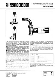
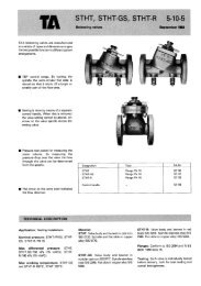
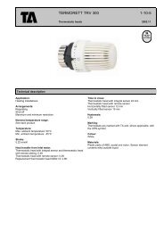
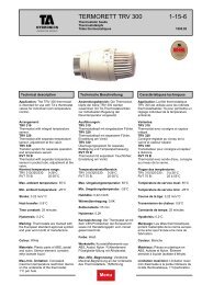
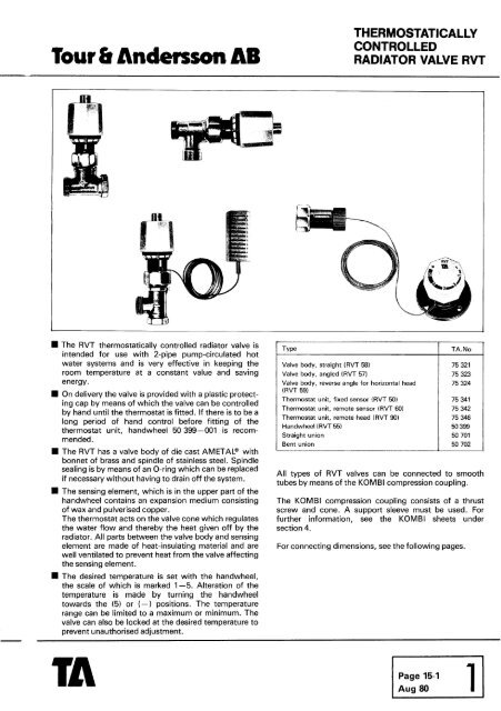
The <strong>RVT</strong> thermostatically controlled radiator valve is<br />
intended for use with 2-pipe pump-circulated hot<br />
water systems and is very effective in keeping the<br />
room temperature at a constant value and saving<br />
energy.<br />
H On delivery the valve is provided with a plastic protect-<br />
ing Cap by means of which the valve can be controlled<br />
by hand until the thermostat is fitted. If there is to be a<br />
long period of hand control before fitting of the<br />
thermostat unit, handwheel 50 399-001 is recom-<br />
mended.<br />
H The <strong>RVT</strong> has a valve body of die cast AME<strong>TA</strong>L@ with<br />
bonnet of brass and spindle of stainless steel. Spindle<br />
sealing is by means of an O-ring which can be replaced<br />
if necessary without having to drain off the system.<br />
The sensing element, which is in the upper part of the<br />
handwheel contains an expansion medium consisting<br />
of wax and pulverised copper.<br />
The thermostat acts on the valve cone which regulates<br />
the water flow and thereby the heat given off by the<br />
radiator. All parts between the valve body and sensing<br />
element are made of heat-insulating material and are<br />
well ventilated to prevent heat from the valve affecting<br />
the sensing element.<br />
The desired temperature is set with the handwheel,<br />
the scale of which is marked 1-5. Alteration of the<br />
temperature is made by turning the handwheel<br />
towards the (5) or (-1 positions. The temperature<br />
range can be limited to a maximum or minimum. The<br />
valve can also be locked at the desired temperature to<br />
prevent unauthorised adjustment.<br />
Valve body, straight (<strong>RVT</strong> 58)<br />
Valve body, angled (<strong>RVT</strong> 57)<br />
Valve body, reverse angle for horizontal head<br />
(<strong>RVT</strong> 59)<br />
Thermostat unit, fixed sensor (<strong>RVT</strong> 50)<br />
Thermostat unit, remote sensor (<strong>RVT</strong> 60)<br />
Thermostat unit, remote head (<strong>RVT</strong> 90)<br />
Handwheel (<strong>RVT</strong> 55)<br />
Straight union<br />
Bent union<br />
THERMOS<strong>TA</strong>TICALLY<br />
CONTROLLED<br />
RADIATOR VALVE <strong>RVT</strong><br />
All types of <strong>RVT</strong> valves can be connected to smooth<br />
tubes by means of the KOMBI compression coupling.<br />
The KOMBI compression coupling consists of a thrust<br />
screw and cone. A support sleeve must be used. For<br />
further information, see the KOMBI sheets under<br />
section 4.<br />
For connecting dimensions, see the following pages.
TECHNICAL DESCRIPTION - THERMOS<strong>TA</strong>TICALLY CONTROLLED RADIATOR VALVE <strong>RVT</strong><br />
Applications:<br />
Nominal range of<br />
temperature:<br />
Max. pressure:<br />
Max. differential pressure:<br />
Max. working<br />
temperature:<br />
Dead time:<br />
Time constant:<br />
Hysteresis:<br />
The sensibility of<br />
differential pressure:<br />
Heat conduct:<br />
The approx temperature<br />
of the set points:<br />
Surface treatment:<br />
Length of capillary tube:<br />
Packing:<br />
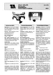
The valve characteristic<br />
Capacity %<br />
O 10 20 30 40 50 60 70 80 90 100%<br />
Lift Valve fully open<br />
Heating installations, 2 pipe systems with pumped circulation.<br />
1 .O MPa = 10 bar -140 psi<br />
5 mWG * 50 kPa = 0.5 bar (7.1 Ibf/in2)<br />
With very small water quantities, e.g. when a thermostatically regulated valve is<br />
close to the shut-off position, a higher pressure drop is acceptable, but not more<br />
than 20 m (66 ft) water column.<br />
+ 120' C. (The thermostatic head may not be affected to a higher temperature<br />
than + 50' C (122' F) or lower than - 15O C (59' F).<br />
1,3 f 0.1 min<br />
26.5 * 0.3 min<br />
0.6 t 0.05' C<br />
Nickel-plated<br />
Marking<br />
Thermostatic head<br />
1. The control mark of the Swedish Board of Urban<br />
Planning on the flat top of the handwheel. 7"<br />
2. The French control mark Norm de France on the flat<br />
top of the handwheel.<br />
3. Date of manufacturing eg 7914 (ie 1979 w 14)<br />
Valve body<br />
1. Cast: Flow direction arrow<br />
2. Punched: (kv-value) and date of manufacture<br />
1 Page<br />
15-2<br />
Aug 80<br />
2 m, 5 m or 8 m. Applicable for valves with separate sensing element.<br />
The valves are packed in cardboard boxes according to packing list.<br />
Pressure drop graph<br />
The lines give the pressure drop at a temperature<br />
deviation of 2 O C = nominal lift<br />
Pressure drop m W<br />
5<br />
Nominal lift will be adjusted with the protection Cap in the<br />
following manner:<br />
1. Close the valve<br />
2. Open it slowly till the moment when the heat first is<br />
faintly recognized.<br />
3. Then open it two graduations more.<br />
The valve coefficient k" at the nominal lift: size 318 =<br />
0.22 size 112 = 0.45 size 314 = 0.55.<br />
Biörsell, Borais<br />
1-
<strong>Tour</strong> & <strong>Andersson</strong> <strong>AB</strong><br />
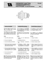
75 321 (<strong>RVT</strong> 58)<br />
Valve body straight<br />
75 323 (<strong>RVT</strong> 57)<br />
Valve body, angle<br />
75 324 (<strong>RVT</strong> 59)<br />
Valve body, reverse angle for<br />
horizontal head<br />
75 341 (<strong>RVT</strong> 50)<br />
Thermostat head, fixed sensor<br />
THERMOS<strong>TA</strong>TICALLY<br />
CONTI IOLLED<br />
RADIA' 'OR VALVE <strong>RVT</strong><br />
8-24' (46-75' F)<br />
max 20° C (68' F)<br />
max 21 C (70' F)<br />
max 22O C (72' F)<br />
75 342 (<strong>RVT</strong> 60)<br />
Thermostat unit, remote sensor<br />
t- 69 1 max 20' C (68' F)<br />
max 21 C (70' F)<br />
max 22' C (72' F)<br />
8-24' C (46-75' F)<br />
8-24' C (46-75' F)<br />
75 346 ( <strong>RVT</strong> 90)<br />
Thermostat unit, remote head<br />
"Thermostat units with max. limitation to other temperatures can be supplied to special order.<br />
Length for<br />
capillary tubc<br />
2 m<br />
Page 15-3<br />
Aug 80 1<br />
Veight<br />
kg<br />
0.21<br />
0.30<br />
0.42
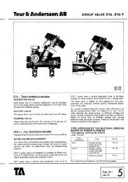
50 399 ( <strong>RVT</strong> 55)<br />
Handwheel<br />
Weight 0.02 kg<br />
50 701<br />
Straight union<br />
KRK<br />
50 702<br />
Bent union<br />
All valves can be connected to smooth tubes<br />
by means of KOMBI compression couplings<br />
KOMBI is to be ordered separately.<br />
When ordering, specify article nusmber of KOMBI coupling<br />
(58 2351, connection R and pipe (mm).<br />
Example: 53 235- 10x8. Further information concerning<br />
KOMBI couplings can be found under section 4.<br />
1 Page<br />
15-4<br />
Aug 80<br />
Conr<br />
DN<br />
10<br />
15<br />
20<br />
10<br />
15<br />
20<br />
R<br />
KRK<br />
KRK<br />
= Cylindrical pipe thread<br />
= Short tapered pipe thread<br />
Weight<br />
kg<br />
0.05<br />
0.09<br />
0.14<br />
Björsell, BorAs
<strong>Tour</strong> b <strong>Andersson</strong> <strong>AB</strong><br />
Material:<br />
M = Brass<br />
P1 = <strong>AB</strong>S-Plastic<br />
P2 = Glassfibre reinforced Nylon<br />
P3 = Glassfibre reinforced Norylplastic<br />
G = Rubber<br />
S = Steel<br />
SS = Steel Stainless<br />
THERMOS<br />
i <strong>RVT</strong> 50)<br />
75 341 - 601<br />
Page 15-5<br />
Aug 80 1<br />
<strong>RVT</strong><br />
Service sheet<br />
UNIT