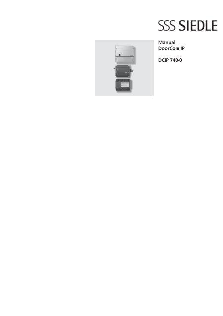
Manual DoorCom IP DCIP 740-0 - Siedle
Manual DoorCom IP DCIP 740-0 - Siedle
Manual DoorCom IP DCIP 740-0 - Siedle

You also want an ePaper? Increase the reach of your titles
YUMPU automatically turns print PDFs into web optimized ePapers that Google loves.
<strong>Manual</strong><br />
<strong>DoorCom</strong> <strong>IP</strong><br />
DC<strong>IP</strong> <strong>740</strong>-0
Contents<br />
1 System description 3<br />
2 Safety remarks 3<br />
System requirements 3<br />
3 Structure<br />
DC<strong>IP</strong> <strong>740</strong>-0 4<br />
Group calculation<br />
Max. number of PC users 5<br />
Terms 6<br />
4 Components<br />
Calling 8<br />
Input module, camera module 9<br />
Power supply, programming,<br />
<strong>IP</strong> video server 10<br />
Software 11<br />
<strong>Siedle</strong> Multi 12<br />
5 Installation<br />
Wiring diagrams DC<strong>IP</strong> <strong>740</strong>-0<br />
Terminals DC<strong>IP</strong> <strong>740</strong>-0 14<br />
LED display SIVS 610 15<br />
Block diagrams 16<br />
Wiring diagram <strong>Siedle</strong> Multi 17<br />
6 Commissioning<br />
DC<strong>IP</strong> <strong>740</strong>-... 20<br />
SIM <strong>740</strong>-... 21<br />
Multicasting 22<br />
Configuration software DC<strong>IP</strong> CO 24<br />
Software client DC<strong>IP</strong> SC 26<br />
7 Setting the speech volume,<br />
level adjustment<br />
DC<strong>IP</strong> <strong>740</strong>-... 28<br />
8 <strong>DoorCom</strong> DCA <strong>740</strong>-01 29<br />
9 Factory reset 29<br />
10 <strong>DoorCom</strong> <strong>IP</strong> FAQ and<br />
trouble shooting 30<br />
11 Glossary, index 33<br />
2
1 System description<br />
<strong>DoorCom</strong> <strong>IP</strong> <strong>740</strong>-0<br />
<strong>DoorCom</strong> <strong>IP</strong> <strong>740</strong>-0<br />
<strong>Siedle</strong> <strong>DoorCom</strong> <strong>IP</strong> links the <strong>Siedle</strong><br />
world of building communication<br />
to the <strong>IP</strong> world. Door calls are<br />
transformed via the <strong>DoorCom</strong> <strong>IP</strong> and<br />
transmitted via the <strong>IP</strong> network<br />
to certain PCs. If video cameras<br />
are fitted at the door station, the<br />
picture of the visitor is additionally<br />
transmitted. The <strong>DoorCom</strong> <strong>IP</strong><br />
Software Client is used here as<br />
a virtual in-house telephone for<br />
communication to the door station.<br />
The Software Client must be<br />
installed on every PC in the network<br />
which is intended to receive a door<br />
call. Assignment of door calls to the<br />
Software Clients takes place using<br />
an IWA address (Interface Working<br />
Address) which is entered in the<br />
<strong>DoorCom</strong> <strong>IP</strong> with the aid of the<br />
configuration software.<br />
DC<strong>IP</strong> <strong>740</strong>-0<br />
The <strong>DoorCom</strong> <strong>IP</strong> <strong>740</strong>-... serves as<br />
an interface between a <strong>Siedle</strong> Multi<br />
system and an <strong>IP</strong> network.<br />
The <strong>DoorCom</strong> <strong>IP</strong> is able to display<br />
the picture on the PC monitor in<br />
conjunction with the <strong>Siedle</strong> Software<br />
Client and at the same time hold the<br />
door call via the PC. The door call<br />
can optionally also be held over the<br />
telephone system using a telephone,<br />
while the picture is displayed by<br />
the Software Client and all control<br />
functions such as door release can<br />
also be initiated by the software. For<br />
this, a DCA <strong>740</strong>-01 must additionally<br />
be connected to the <strong>DoorCom</strong> <strong>IP</strong>.<br />
2 Safety remarks<br />
System requirements<br />
Danger<br />
Mounting, installation and<br />
servicing work on electrical<br />
devices may only be performed<br />
by a suitably qualified electrician.<br />
Failure to observe this regulation<br />
could result in the risk of serious<br />
damage to health or fatal injury<br />
due to electric shocks.<br />
• When working at the device,<br />
observe the instructions for mains<br />
cut-off.<br />
• Observe the standard DIN EN<br />
60065!<br />
When establishing the electronic<br />
connection, observe the<br />
requirements of VDE 0805 / EN<br />
60950.<br />
• An all-pole mains switch must be<br />
provided in the building installation<br />
with a contact opening<br />
of at least 3 mm.<br />
• Ensure that the connection point<br />
in the building installation is fused<br />
with max. 16 A.<br />
• When planning, the required<br />
distributor space for switch panel<br />
mounted devices must be taken into<br />
account.<br />
• External voltages >30 V AC/<br />
DC must not be injected into the<br />
in-house telephones.<br />
Devices with 230 V connection<br />
In accordance with DIN VDE 0100<br />
Part 410, Section 411.1.3 ensure<br />
that the <strong>DoorCom</strong> installation and<br />
the mains voltage are securely<br />
isolated. The sheathing of the<br />
connection cable (safety extra-low<br />
voltage) should only be stripped<br />
back far enough to ensure that<br />
reliable connection is possible.<br />
For mains connection<br />
! and network settings such as<br />
assignment of the <strong>IP</strong> address, the<br />
responsible network administrator<br />
must be consulted.<br />
Find out about the necessary safety<br />
measures and system requirements<br />
before starting installation and<br />
commissioning of the <strong>DoorCom</strong> <strong>IP</strong>.<br />
System requirements<br />
for the configuration software<br />
• PC with Intel Pentium III from<br />
1 GHz or comparable processor<br />
• at least 256 MB RAM<br />
• min. 25 MB hard disk memory<br />
• Serial COM interface RS232 or<br />
USB interface<br />
• CD-ROM drive for installation<br />
• VGA graphic card with<br />
at least 1024 x 768 pixel<br />
• Operating system Windows 2000/<br />
XP<br />
• Admin rights for installation<br />
Additional memory capacity is<br />
required for:<br />
• Acrobat Reader 7<br />
• Microsoft Internet Explorer from<br />
version 4<br />
System requirements<br />
for the Software Client<br />
• Operating system Microsoft<br />
Windows 2000/XP<br />
• Pentium IV from 1.8 GHz or<br />
compatible CPUs<br />
• min. 256 MB RAM<br />
• Graphic card with<br />
at least 1024 x 768,<br />
128 MB and 16 bit colour depth<br />
MPEG 4 capability<br />
• 100 Mbit Ethernet card<br />
• Sound card<br />
• Microsoft DirectX 9.0b or newer<br />
• Microsoft Internet Explorer<br />
from version 4.0 for reading the help<br />
Speech quality<br />
The audio quality (speech<br />
transmission) is highly dependent on<br />
the quality of the audio components<br />
built into the PC (headset, handset<br />
and sound card).<br />
3
3 Structure DC<strong>IP</strong> <strong>740</strong>-0<br />
<strong>Siedle</strong> Multi with link to system telephone<br />
Camera assignment mode<br />
DC<strong>IP</strong> <strong>740</strong>-...<br />
<strong>Siedle</strong> Multi link<br />
The DC<strong>IP</strong> <strong>740</strong>-... behaves in<br />
the system in the same way as<br />
an internal call station and is<br />
consequently bound by the same<br />
system limitations (range and<br />
number of users). The DC<strong>IP</strong> <strong>740</strong>-...<br />
can be used in two operating modes<br />
(camera assignment and monitor<br />
assignment). The operating mode is<br />
set in the SIM <strong>740</strong>-... The operating<br />
mode depends on the arrangement<br />
and system topology.<br />
The DC<strong>IP</strong> <strong>740</strong>-... comprises the<br />
components:<br />
• SIVS 610-.., system interface video<br />
server. Processing and adjustment of<br />
data, audio and video.<br />
• <strong>IP</strong>VS 600- .., <strong>IP</strong> video server.<br />
Transmits data, audio and video to<br />
the <strong>IP</strong> network.<br />
• SIM <strong>740</strong>-... system interface Multi.<br />
Interface to <strong>Siedle</strong> Multi<br />
Camera assignment mode<br />
The SIM <strong>740</strong>-... is assigned to<br />
a door / camera. In this mode,<br />
the device can be assigned up<br />
4<br />
PRI 602-... USB<br />
to 49 different call destinations<br />
which correspond to the functions<br />
of 49 Multi telephones. In this<br />
operating mode, a DC<strong>IP</strong> <strong>740</strong>-...<br />
is required for each door. This<br />
operating mode is advisable in<br />
systems with a small number of<br />
doors and a large number of PC<br />
users.<br />
Monitor assignment mode:<br />
Up to a maximum of 4 call<br />
destinations, i.e. <strong>Siedle</strong> Multi system<br />
addresses, can be assigned to the<br />
interface SIM <strong>740</strong>-...<br />
These correspond to the functions<br />
of the 4 Multi telephones. The call<br />
destination can be dialled from<br />
every door within the <strong>Siedle</strong> Multi<br />
(max. 254). This operating mode<br />
is advisable in systems with a<br />
large number of doors and a small<br />
number of PC users.<br />
Power supply<br />
The DC<strong>IP</strong> <strong>740</strong>-... is supplied directly<br />
from the <strong>Siedle</strong>-Multi bus. A<br />
separate supply is consequently not<br />
required. An optionally connected<br />
DCA <strong>740</strong>-01 is supplied from the<br />
SIVS 610-...<br />
The a/b public network interface is<br />
supplied from the TC system. It is<br />
not possible to connect an individual<br />
public network telephone directly to<br />
the a/b line of the DCA <strong>740</strong>-01.<br />
The DC<strong>IP</strong> <strong>740</strong>-... or the <strong>IP</strong>VS 600-...<br />
is linked using a standard network<br />
cable with RJ45 plug to the <strong>IP</strong><br />
network.<br />
Functions<br />
• Door call from the <strong>Siedle</strong> Multi<br />
system and signalling to the PC<br />
• Text display of which door or<br />
which Multi telephone is calling.<br />
• Door release actuation by means<br />
of a mouse click<br />
• Light actuation by means of a<br />
mouse click<br />
• Selective dialling of a connection<br />
to a Multi door station or Multi<br />
in-house telephone.<br />
• Initiation of control and switching<br />
functions via a mouse click to the<br />
Multi system<br />
• Reception of status messages from<br />
the <strong>Siedle</strong> Multi bus<br />
• Speech connection via PC<br />
(headset) or optionally via the<br />
telephone.
Monitor assignment mode<br />
Commissioning and<br />
programming<br />
After connection of the supply<br />
voltage, the devices SIM <strong>740</strong>-... and<br />
SIVS 610-... can be programmed<br />
with the aid of a PRI 602 via the PC.<br />
(See commissioning chapter 6)<br />
No programming is required for the<br />
DCA <strong>740</strong>-01. For programming and<br />
configuration of the TC system, see<br />
the relevant product information<br />
and programming instructions of the<br />
manufacturer.<br />
Mounting and installation<br />
The DC<strong>IP</strong> <strong>740</strong>-... can be connected<br />
at any optional point of the <strong>Siedle</strong><br />
Multi system bus. The devices are<br />
intended for switch panel mounting.<br />
These should preferably be mounted<br />
directly one next to the other.<br />
The maximum conductor length<br />
of the device connection must not<br />
exceed 1 metre.<br />
The SIM <strong>740</strong>-... is linked to the<br />
SIVS 610-... with 6 cores. Actuation<br />
of the link between the SIVS 610-...<br />
and the <strong>IP</strong>VS 600-... takes place via<br />
the patch cable.<br />
PRI 602-... USB<br />
Performance features<br />
• Transmission of door calls with/<br />
without video via the Ethernet to<br />
PC users<br />
• Free combination of PC call<br />
stations and Multi <strong>Siedle</strong> terminals<br />
• Audio transmission also possible<br />
via the telephone network<br />
(DCA <strong>740</strong>-01)<br />
• Full duplex calls between door call<br />
station and Software Client<br />
• Actuation of the door release and<br />
light possible from the PC with a<br />
mouse click.<br />
• Video: MPEG-4 (ISO/IEC 14496)<br />
Codec, Audio: G.711; (300Hz -<br />
3.4KHz)<br />
• From 1 door up to 49 different PC<br />
call users can be connected<br />
• Selective connection to a door<br />
station. (Audio and/or video)<br />
• Parallel call possible to max. 25 PC<br />
users<br />
• With the TLC 640-... in<br />
combination with code lock module<br />
COM 611-..., alphabetical input<br />
module AEM 645-0 or display call<br />
module DRM 611-... direct calls are<br />
possible from PC users.<br />
3 Group calculation<br />
Max. number of PC users<br />
Calculation<br />
For calculation of the maximum<br />
number of possible PC users (single<br />
and parallel calls), the following rules<br />
are applied:<br />
• In general, an <strong>IP</strong>VS can manage a<br />
maximum of 50 registrations.<br />
• In the monitor assignment mode,<br />
the maximum number of users is<br />
four.<br />
This applies depending on which<br />
limit is reached first.<br />
• Every PC user to which a door call<br />
has been established currently occupies<br />
2 registrations in the <strong>IP</strong>VS.<br />
Camera assignment mode:<br />
• If no groups are created, a<br />
maximum of 49 single PC users can<br />
be integrated. If one of these PC<br />
users is called, it currently occupies 2<br />
registrations, the others occupy only<br />
one each. In total, this adds up to<br />
1*2+48=50, which is the maximum<br />
possible assignment per <strong>IP</strong>VS.<br />
• If several groups are created, the<br />
biggest group is decisive for the<br />
calculation. The maximum group<br />
size is 25. If this group is called,<br />
each PC user currently occupies 2<br />
5
egistrations. In total, this adds up<br />
to 25*2=50, which is the maximum<br />
possible assignment per <strong>IP</strong>VS.<br />
In the following is a list with five<br />
combinations. Each example comprises<br />
a group with a different number<br />
of users and individual clients.<br />
Clients Individual Calculation<br />
in group Clients<br />
5 40 5*2+40=50<br />
10 30 10*2+30=50<br />
15 20 15*2+20=50<br />
20 10 20*2+10=50<br />
25 0 25*2+0=50<br />
Example in case of several<br />
groups:<br />
The following is a combination<br />
example comprising two groups<br />
and five individual clients, with each<br />
group and each individual client<br />
occupying one address. Consequently<br />
a total of seven addresses are used<br />
in the system.<br />
Group 1: 20 PC users<br />
Group 2: 5 PC users<br />
Clients: 5 individual PC users<br />
• If the biggest group (group 1) is<br />
called, this group occupies 20*2=40<br />
registrations in the <strong>IP</strong>VS. Group 2<br />
and the individual PC users each<br />
occupy 5 registrations. In total, this<br />
adds up to 20*2+5+5=50, which is<br />
the maximum possible assignment<br />
per <strong>IP</strong>VS.<br />
Monitor assignment mode:<br />
• If no groups are created, a<br />
maximum of 4 single PC users can<br />
be integrated. If one of these PC<br />
users is called, it currently occupies<br />
2 registrations, the others occupy<br />
only one each. In total, this adds<br />
up to 1*2+3=5. In this operating<br />
mode, this represents the maximum<br />
number of users.<br />
• If several groups are created, the<br />
biggest group is decisive for the<br />
calculation. The maximum group<br />
size is 25. If this group is called,<br />
each PC user currently occupies 2<br />
registrations. In total, this adds up<br />
6<br />
to 25*2=50, which is the maximum<br />
possible assignment per <strong>IP</strong>VS.<br />
In the following is a list with four<br />
combinations. Each example comprises<br />
a group with a different number<br />
of users and individual clients.<br />
Clients Individual Calculation<br />
in group Clients<br />
23 3 23*2+3=49<br />
24 2 24*2+2=50<br />
24 1 24*2+1=49<br />
25 0 25*2+0=50<br />
Example in case of several<br />
groups:<br />
The following is a combination<br />
example comprising two groups and<br />
two individual clients, with each<br />
group and each individual client<br />
occupying one address. Consequently<br />
a total of four addresses are used<br />
in the system.<br />
Group 1: 20 PC users<br />
Group 2: 8 PC users<br />
Clients: 2 individual PC users<br />
• If the biggest group (group 1) is<br />
called, this group occupies 20*2=40<br />
registrations in the <strong>IP</strong>VS. Group 2<br />
occupies 8 registrations and the<br />
two individual PC users each<br />
occupy one. In total, this adds up to<br />
20*2+8+2=50, which is the maximum<br />
possible assignment per <strong>IP</strong>VS.<br />
For parallel calls to groups, note the<br />
section on multicasting, page 22.<br />
3 Terms<br />
Camera assignment<br />
A <strong>Siedle</strong> Multi door station can be<br />
assigned up to 49 different PC users.<br />
This operating mode is only possible<br />
with DC<strong>IP</strong> <strong>740</strong>-...<br />
Client<br />
PC user connected to a network.<br />
Full duplex<br />
Both users (PC client and door<br />
station) have an unrestricted<br />
speech connection. Open duplex<br />
communication, i.e. as opposed to<br />
the simplex speech mode.<br />
Gateway<br />
Gateways link two different<br />
networks and create connections<br />
across network boundaries. During<br />
this process, both the physical<br />
transmission modes and also<br />
protocols and addresses are adjusted<br />
accordingly.<br />
Half duplex<br />
Two speaking users have one speech<br />
connection which they can use<br />
alternately, also known as push to<br />
talk.<br />
HTTP<br />
The Hypertext Transfer Protocol is a<br />
protocol used for the transmission<br />
of data via a network. It is used<br />
mainly to load websites and other<br />
data from the Internet into a web<br />
browser.<br />
Hub<br />
The term hub when used in relation<br />
to network technology describes a<br />
device which links network nodes in<br />
a star formation. Normally, the term<br />
hub is used to denote a multiport<br />
repeater. It is used in order to link<br />
network nodes or other hubs, for<br />
example by means of an Ethernet.<br />
<strong>IP</strong> address<br />
Internet Protocol address<br />
An <strong>IP</strong> address is a number which<br />
permits PCs and other devices in<br />
an <strong>IP</strong> network to be addressed. In<br />
technical terms, the number is a<br />
32- or 128-bit binary number.
<strong>IP</strong><br />
Internet Protocol<br />
The <strong>IP</strong> is a network protocol in<br />
widespread use in computer<br />
networks. <strong>IP</strong> forms the first layer of<br />
the Internet protocol family which<br />
is independent of the transmission<br />
medium. This means that computers<br />
can be grouped within a network<br />
into logical units known as subnets<br />
by means of an <strong>IP</strong> address and<br />
subnet mask.<br />
IGMP V3<br />
The Internet Group Management<br />
Protocol is based on the Internet<br />
Protocol (<strong>IP</strong>) and permits <strong>IP</strong><br />
multicasting (group communication)<br />
in the Internet. <strong>IP</strong> multicasting is the<br />
distribution of <strong>IP</strong> packages under<br />
an <strong>IP</strong> address to several stations<br />
simultaneously. Here, it is possible to<br />
specify which source is required for<br />
the multicast stream.<br />
IWA<br />
Interface Working Address<br />
Six-digit address with which the<br />
system interface video server<br />
SIVS 600-... addresses the PC users.<br />
These IWA addresses are stored in<br />
the Software Client.<br />
LAN<br />
Local Area Network<br />
Local, cable-linked network.<br />
Monitor assignment<br />
Up to 254 <strong>Siedle</strong> Multi door stations<br />
can be assigned to a maximum<br />
of 4 different PC users. This<br />
operating mode is only possible with<br />
DC<strong>IP</strong> <strong>740</strong>-... .<br />
Multicasting<br />
Term to denote group/parallel calls<br />
with video image to several PC users<br />
which have the Software Client<br />
installed. For this to be possible, the<br />
UDP and IGMP V3 protocols must be<br />
implemented in the network.<br />
Push to Talk<br />
In case of a connection using the<br />
half-duplex mode (push to talk) a<br />
button always has to be pushed to<br />
change the speech direction.<br />
Router<br />
A router is a network device which<br />
links several computer networks.<br />
Network packages of a protocol<br />
arriving at the router are analysed<br />
for information and forwarded or<br />
routed to the intended destination<br />
network.<br />
RS232<br />
Designation for a serial interface, for<br />
instance the COM interface of a PC.<br />
RS485<br />
Interface for serial data transmission<br />
in the half-duplex mode.<br />
Transmission to a pair of cores.<br />
Server<br />
A server is a program which waits to<br />
be contacted by a client program,<br />
after which it exchanges data with<br />
the client program. The hardware<br />
on which the server runs is known<br />
as the host.<br />
Subnet mask<br />
The subnet mask, also known<br />
as network mask, is a bit mask<br />
which separates an <strong>IP</strong> address into<br />
a network and a device or host<br />
section. It is used in <strong>IP</strong> networks in<br />
order to make routing decisions.<br />
TCP<br />
Transmission Control Protocol<br />
The TCP is a protocol which<br />
determines the way in which data<br />
is exchanged between computers.<br />
All operating systems in modern<br />
computers have TCP capability and<br />
use this protocol for data exchange<br />
with other computers. The protocol<br />
is a reliable, connection-oriented<br />
transport protocol used in computer<br />
networks.It is part of the internet<br />
protocol family, which forms the<br />
foundation of the Internet.<br />
UDP<br />
User Datagram Protocol<br />
The UDP is a minimal connectionless<br />
network protocol which belongs to<br />
the transport layer of the Internet<br />
protocol family. It is the task of the<br />
UDP to assign data transmitted via<br />
the network to the right application.<br />
Vario bus<br />
Various different input and control<br />
units can be connected to the Vario<br />
bus. It comprises 4 cores. The Vario<br />
bus is a RS485-bus. The information<br />
will be transfered on the Vario bus<br />
protocol.<br />
Web browser<br />
Software for the display and<br />
indication of Internet pages or<br />
corresponding configuration pages.<br />
E.g. Internet Explorer or Firefox.<br />
7
4 Components for DC<strong>IP</strong> <strong>740</strong>-...<br />
Call buttons<br />
8<br />
BTM 650-01 - BTM 650-04<br />
Bus call button modules for In-Home<br />
bus. 1-4 call buttons, integrated LED<br />
lighting. Connection via ribbon cable<br />
to the TME 645-... Power supply<br />
to the LED lighting via terminals b<br />
and c with 12 V AC/DC, current<br />
consumption 25 mA per bus call<br />
button module BTM 650-...<br />
TME 645-0<br />
Call button module extension<br />
with interface to the Vario bus for<br />
max. 8 TME 645-... . Suitable for<br />
connection of call button module<br />
BTM 650 -... A maximum of 16<br />
bus call button modules can be<br />
connected per TME 645-… . With<br />
an acoustic signal which sounds on<br />
button assignment. The call button<br />
modules are connected to the<br />
TME 645-… by means of a ribbon<br />
TM 612-1 - TM 612-4<br />
Call button modules, potential-free<br />
buttons, 1-4 call buttons, integrated<br />
LED lighting. Connection by means<br />
of terminal block. Power supply<br />
to the LED lighting by means of<br />
terminal b and c with 12 V AC/DC,<br />
current consumption 25 mA per call<br />
button module TM 612-...<br />
Used as call buttons 1-4 directly at<br />
the SIVS 600-...<br />
TME 640-0<br />
Call button module extension in<br />
protective housing with screw<br />
terminals, for connection of call<br />
button modules TM 612-... or call<br />
buttons of other makes.<br />
A maximum of 16 call button<br />
modules can be connected to the<br />
TME 640-… by means of a matrix<br />
installation.<br />
Dimensions: 100 x 50 x 20 mm<br />
cable.<br />
Dimensions: 99 x 99 mm
4 Components for DC<strong>IP</strong> <strong>740</strong>-...<br />
Input module, camera module<br />
CMC 612-...<br />
Camera module, colour. Integrated<br />
2-step heating system, day/night<br />
switchover, infrared lighting and<br />
video signal transformer. Power<br />
supply using line rectifier NG 600-...<br />
or VNG 602-... With <strong>Siedle</strong> Multi via<br />
PCM 640-.../NG 600-..., NG 608-...<br />
or NG 640-... Heating power supply<br />
12 V AC, 100 mA.<br />
COM 611-01<br />
Code lock module as an input unit<br />
in conjunction with the <strong>Siedle</strong> Vario<br />
bus.<br />
A C button for deleting incorrect<br />
inputs. LED as status display<br />
(external potential-free contact).<br />
Operating voltage 12 V AC /DC<br />
Current consumption max. 100 mA<br />
AEM 645-0<br />
Alphabetical input module with<br />
keypad A - I. Input unit for<br />
alphanumerical selection of PC users.<br />
For use in <strong>Siedle</strong> Multi systems only<br />
in conjunction with the TLC 640-02,<br />
COM 611-01<br />
DIM 640-0 and SIVS 600-...<br />
Operating voltage 12 V AC /DC<br />
Current consumption max. 100 mA<br />
DRM 611-0<br />
Display call module as an input unit<br />
with 4-line display for placing door<br />
calls.<br />
To scroll through the name index,<br />
there are two arrow keys provided<br />
for „up/down“. An external DR<br />
button can be connected.<br />
• 4-line display x 18 characters each,<br />
with LED backlighting<br />
• 3 displacement-free piezo buttons<br />
• Button actuation confirmed by<br />
Ambient temperatue<br />
-20°C to +70°C<br />
Dimensions: 99 x 99 mm<br />
acoustic tone<br />
• Backlit symbols<br />
Operating voltage 12 V AC/DC<br />
• Current consumption max.<br />
200 mA<br />
Ambient temperature<br />
-20°C to +70°C<br />
Dimensions: 99 x 99 mm<br />
9
4 Components for DC<strong>IP</strong> <strong>740</strong>-...<br />
Power supply, programming, video server<br />
10<br />
NG 600-0<br />
Line rectifier in 10-grid switch panel<br />
housing for universal power supply.<br />
Suitable for surface mounting with<br />
ZAP 10-0. Primary 230 V AC, 50 Hz,<br />
+6%-10%<br />
Secondary b/c: 14 V AC, 1 A;<br />
+/-: 24-28 V DC, 0.7 A<br />
Ambient temperature 0°C to +40°C,<br />
protection rating <strong>IP</strong> 20<br />
Dimensions: 180 x 89 x 60 mm<br />
PRI 602-... USB<br />
Programming interface for<br />
connection of a Windows PC via<br />
USB interface to the Vario bus.<br />
Required for configuration of the<br />
system interface video server with<br />
software DC<strong>IP</strong> CO 600-... version<br />
1.1. or higher.<br />
<strong>IP</strong>VS 600-0<br />
System interface video server<br />
Processing and adjustment of audio<br />
and video, transmission of data,<br />
audio and video to the <strong>IP</strong> network.<br />
Dimensions: 112 x 85 x 40 mm<br />
DCA <strong>740</strong>-01<br />
The <strong>DoorCom</strong> Analog DCA <strong>740</strong>-01<br />
can be connected to a universal a/b<br />
interface.<br />
In conjunction with the DC<strong>IP</strong> <strong>740</strong>-...<br />
it serves as an alternative speech<br />
connection if no speech connection<br />
via PC is preferred.<br />
Connection takes place at the<br />
standardized a/b interface of a TC<br />
system (analogue PBX extension) or<br />
directly at the analogue telephone<br />
network.<br />
Dimensions: 107 x 89 x 60 mm
4 Device overview for DC<strong>IP</strong> <strong>740</strong>-...<br />
Software<br />
DC<strong>IP</strong> SC 600-0<br />
<strong>DoorCom</strong> <strong>IP</strong> Software Client PC<br />
program, which depicts a virtual<br />
house telephone with video on a PC<br />
monitor.<br />
Door calls with video are possible to<br />
one or more <strong>Siedle</strong> door stations.<br />
Execution of switching and control<br />
functions such as door release, light<br />
switch or display of messages on the<br />
PC monitor.<br />
For each installation of the Software<br />
DC<strong>IP</strong> CO 600-0<br />
<strong>DoorCom</strong> <strong>IP</strong> configuration software<br />
PC program for set-up and<br />
programming of the <strong>Siedle</strong> interface<br />
video server<br />
SIVS 610-... Programming takes<br />
place via the USB programming<br />
interface PRI 602-... USB<br />
configuration software version 1.1.<br />
or higher.<br />
Commissioning software for the<br />
administrator.<br />
CD contains<br />
• <strong>DoorCom</strong> <strong>IP</strong> Software Client<br />
(DC<strong>IP</strong> SC 600-0)<br />
• <strong>DoorCom</strong> <strong>IP</strong> Configuration<br />
software (DC<strong>IP</strong> CO 600-0)<br />
• <strong>DoorCom</strong> <strong>IP</strong> <strong>Manual</strong><br />
• <strong>Siedle</strong> default configuration for<br />
<strong>IP</strong>VS 600-...<br />
• Java Runtime Environment (JRE)<br />
5.0<br />
• Microsoft Installer 3.1<br />
Client on a PC, a licence is required<br />
for the DC<strong>IP</strong> SC 600-0.<br />
11
4 Device overview only DC<strong>IP</strong> <strong>740</strong>-...<br />
<strong>Siedle</strong> Multi<br />
12<br />
SIVS 610-0<br />
System interface video server,<br />
for connection of <strong>Siedle</strong> Multi to<br />
the <strong>IP</strong>VS 600-0. The SIM <strong>740</strong>-0 is<br />
required for connection.<br />
The SIVS 610-... features galvanic<br />
isolation in addition to the<br />
SIVS 600-0.<br />
Dimensions: 144 x 130 x 55 mm<br />
SIM <strong>740</strong>-0<br />
The Multi system interface processes<br />
all Multi data protocols. System<br />
information is managed here and<br />
forwarded in neutral form to the<br />
SIVS. The SIM <strong>740</strong>-... is able to<br />
simulate several Multi telephones,<br />
depending on the operating<br />
mode. Only one of these “virtual<br />
telephones“ can ever be active at<br />
one time, i.e. conduct a call.<br />
Dimensions: 107 x 89 x 60 mm<br />
VMS 641-0<br />
Video monitor switching unit, links<br />
the SIVS 610-... with the Multi<br />
video bus, in order to create the<br />
connection to the corresponding<br />
door call station. Is required in the<br />
monitor assignment mode when<br />
the SIM <strong>740</strong>-... simulates more than<br />
1 user.<br />
Dimensions: 62 x 230 x 35 mm<br />
TLC 640-02<br />
Door loudspeaker controller in 6-grid<br />
switch panel housing. Control unit<br />
to be used between TLM 645-...<br />
and <strong>Siedle</strong>-Multi, for two speech<br />
channels.<br />
Dimensions: 107 x 89 x 60 mm
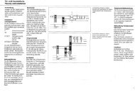
5 Terminals<br />
CMC 612-0<br />
Block diagram CMC 612-0<br />
+M/-M Supply voltage<br />
Video 20 - 30 V DC<br />
Vc/- Actuation from<br />
door loudspeaker for<br />
camera on. With<br />
<strong>DoorCom</strong> <strong>IP</strong> the contact<br />
is permanently<br />
active. Potential - is<br />
switched via<br />
the UPS terminal.<br />
VKA Actuation of<br />
camera distributor -M<br />
is switched<br />
A1/A1 Potential-free contact<br />
for additional<br />
applications<br />
b/c Power supply 12 V AC<br />
for heating<br />
13
5 Terminals<br />
DC<strong>IP</strong> <strong>740</strong>-...<br />
14<br />
a<br />
e<br />
a b c<br />
d e f g<br />
h i j k<br />
c<br />
f<br />
d<br />
b<br />
g<br />
Terminals and LEDs <strong>IP</strong>VS 600-0<br />
a No function<br />
b Connecting socket to the<br />
SIVS 610-...<br />
c RJ45 socket ETH network<br />
connection<br />
d Reset button to recreate the<br />
as-delivered status (after a reset, the<br />
<strong>Siedle</strong> modes must be reinstalled,<br />
see page 30.)<br />
e LED operating status lights up in<br />
green on readiness for operation<br />
f LED L lights up in green with an<br />
existing network connection<br />
g LED T flashes orange on data<br />
transmission via the network<br />
Terminals <strong>IP</strong>VS 600-0<br />
h Video input 1Vss from the<br />
SIVS 610-...<br />
i Audio-Line-In to the SIVS 610-...<br />
j Terminal plug for control signals<br />
k Audio-Line-Out to the SIVS 610-...<br />
Terminals<br />
SIVS 610-...<br />
a Video signal 1 Vss (cinch jack)<br />
b Terminating resistor 75 Ohm<br />
ON/OFF<br />
c IN = video signal 1 Vss input,<br />
D = Video signal 1 Vss throughput<br />
d Terminals for installation<br />
e Connection to <strong>IP</strong>VS 600-...<br />
f Terminals for installation<br />
g Grounding terminal
5 LED display<br />
SIVS 610-... /SIM <strong>740</strong>-0 and <strong>IP</strong>VS 600-...<br />
LED signalling SIVS 610-... /SIM <strong>740</strong>-0<br />
Switching on<br />
LED green LED red Function<br />
OFF ON After reset, power on: Device boots to operating status.<br />
ON ON The boot area is checked. Software runs in the flash<br />
Fast flashing ON After a software update, the boot area is recreated.<br />
This can take up to around 3 minutes.<br />
Operation<br />
LED green LED red Function<br />
ON OFF Booting is complete. All OK. Normal status<br />
Slow flashing OFF Display, a connection exists<br />
Fast flashing OFF A software update or reconfiguration process is under way<br />
Fault<br />
LED green LED red Function<br />
OFF Slow flashing ERROR, software running only in bootloader. Program memory<br />
defective. (Device defective, possibly new software update or<br />
exchange.)<br />
ON Slow flashing Variobus address error (error remedy possible on site)<br />
ON Fast flashing The 15 V power supply (terminal bv, cv) is overloaded. (Error<br />
remedy possible on site) (only SIVS 610-...)<br />
OFF OFF If supply voltage is definitely connected, the device<br />
is defective. (Exchange)<br />
Frequencies: Slow appr. 2 Hz, fast appr. 16 Hz<br />
LED signalling <strong>IP</strong>VS 600-...<br />
The underneath of the <strong>IP</strong> video server <strong>IP</strong>VS 600-... has 3 LEDs which display operating statuses and can provide an<br />
indication of possible errors.<br />
LED operating status Function<br />
OFF <strong>IP</strong>VS 600-... is switched off.<br />
Lights up in green <strong>IP</strong>VS 600-... is switched on<br />
Flashes green Access to the <strong>IP</strong>VS 600-...<br />
Lights up in red (briefly) Start process running<br />
Lights up in red (continuous) Error in the device or failed upload<br />
LED L<br />
Lights up in green Network connection exists<br />
LED T<br />
Lights up in orange Active data transmission via the network<br />
15
5 Terminals<br />
SIVS 610-0, SIM <strong>740</strong>-0<br />
Block diagram SIVS 610-0<br />
G Reference for the inputs<br />
E1–E4<br />
E4 not assigned<br />
E3 not assigned<br />
E2 not assigned<br />
E1 not assigned<br />
cv- Power supply for<br />
bv+ Vario bus, 15 V DC, max.<br />
300 mA<br />
Da/Db Vario bus<br />
+ Supply voltage<br />
- 24 V DC<br />
Tö not used, DR via<br />
Tö TLC 640-02<br />
Li not used<br />
USP Universal Serial Port,<br />
SN1 RF signal, path<br />
SN2 SIM <strong>740</strong>-...–SIVS 610-...<br />
n1 RF signal for<br />
n2 connected<br />
DCA <strong>740</strong>-01<br />
Block diagram SIM <strong>740</strong>-0<br />
S1 Switching output 1<br />
S2 Switching output 2<br />
S3 Switching output 3<br />
S4 Switching output 4<br />
cv- Power supply for<br />
bv+ 15 V DC<br />
1–8 <strong>Siedle</strong> Multi<br />
E1 Input 1<br />
E2 Input 2<br />
E3 Input 3<br />
Da/Db Vario bus<br />
SN1 RF signal, path<br />
SN2 SIM <strong>740</strong>-...–SIVS 610-...<br />
16
5 Installation<br />
DC<strong>IP</strong> <strong>740</strong>-... <strong>Siedle</strong> multi<br />
<strong>Siedle</strong> Multi requires additional supply devices which are not listed in this wiring diagram!<br />
Monitor assignment mode<br />
17
5 Installation<br />
DC<strong>IP</strong> <strong>740</strong>-... <strong>Siedle</strong> multi<br />
18<br />
Camera assignment mode <strong>Siedle</strong> Multi requires additional supply devices which are not listed in this wiring diagram!
DC<strong>IP</strong> <strong>740</strong>-... <strong>Siedle</strong> multi<br />
Functional characteristics<br />
Depending on the operating mode<br />
camera assignment or monitor<br />
assignment, 49 or 4 PC users can<br />
be called.<br />
Calling, speech and door release via<br />
the Software Client DC<strong>IP</strong> SC 600-... .<br />
The Software Client must be<br />
installed on every PC which receives<br />
door calls. Standard call tones for<br />
the Software Client 3-tone chime. A<br />
dedicated *.wav file can be assigned<br />
for each call tone.<br />
It is not possible to listen in to an<br />
existing call from other PC users in<br />
the network.<br />
The door is opened by the called<br />
PC user using a “virtual door<br />
release button”, the light switching<br />
function is actuated using a “virtual<br />
light button”. The door call can be<br />
muted with an optical display on the<br />
monitor.<br />
Camera assignment mode<br />
The SIM <strong>740</strong>-... is assigned to a<br />
door / camera. In this mode, the<br />
device can be assigned up to 49<br />
different call destinations, i.e. <strong>Siedle</strong><br />
Multi system addresses which<br />
correspond to the functions of 49<br />
Multi telephones. In this operating<br />
mode, a DC<strong>IP</strong> <strong>740</strong>-... is required<br />
for each door. This operating<br />
mode is advisable in systems with a<br />
small number of doors and a large<br />
number of PC users.<br />
Monitor assignment mode:<br />
Up to a maximum of 4 call<br />
destinations, i.e. <strong>Siedle</strong> Multi system<br />
addresses, can be assigned to the<br />
interface. These correspond to the<br />
functions of the 4 Multi telephones.<br />
The call destination can be dialled<br />
from every door within the <strong>Siedle</strong><br />
Multi (max. 254). This operating<br />
mode is advisable in systems with a<br />
large number of doors and a small<br />
number of PC users.<br />
Remarks<br />
a) Door release 12 V AC, use at least<br />
20 Ohm (e.g. TÖ 615-...)<br />
• 12 V AC consumers in the wiring<br />
diagram:<br />
• Door release appr. 600 mA<br />
• Light contact load in the door<br />
loudspeaker max. 24 V AC, 2 A<br />
c) Distance of the SIVS 610-... to the<br />
door station max. 200 m with<br />
J-Y(ST)Y 0.8 mm core material.<br />
Distance between the two devices<br />
SIVS 610-... and <strong>IP</strong>VS 600-... in<br />
the distributor max. 1 m. During<br />
installation, ensure that the door<br />
release is laid in a separate cable.<br />
Power supply voltage bv+/cv- of the<br />
SIVS 610 15 V DC, max. 300 mA<br />
When connecting additional devices<br />
to the Vario bus (terminals Da/Db),<br />
the Vario bus requires an additional<br />
power supply.<br />
d) ***Optionally the DCA <strong>740</strong>-01<br />
can be connected to the PBX<br />
extension of a telephone system.<br />
Active door calls can then be routed<br />
via the telephone.<br />
The functional features of the<br />
Software Client can still be used.<br />
19
6 Commissioning<br />
DC<strong>IP</strong> <strong>740</strong>-... <strong>Siedle</strong> multi<br />
The procedure for commissioning<br />
the DC<strong>IP</strong> <strong>740</strong>-... is broken down into<br />
4 steps:<br />
1 Configuration of <strong>IP</strong>VS 600-...<br />
2 Configuration of SIM <strong>740</strong>-...<br />
3 Configuration of SIVS 610-...<br />
4 Installation of the software<br />
DC<strong>IP</strong> SC 600-... on the PCs<br />
Step 1 on this page<br />
Configuration of <strong>IP</strong>VS 600-...<br />
Issue of the <strong>IP</strong> address, subnet mask<br />
address and gateway address for<br />
assignment in the network. In the<br />
case of group calls, issue of the<br />
Multicast address.<br />
Step 2 on pages 21<br />
Configuration of SIM <strong>740</strong>-...<br />
Here, the multi-specific parameters<br />
of the SIM <strong>740</strong>-... are entered.<br />
Selection of whether the<br />
DC<strong>IP</strong> <strong>740</strong>-... should run in the<br />
camera or the monitor mode.<br />
Step 2.1<br />
Configuraion of DRM 611-...<br />
Names are programmed with the<br />
PRS-Software. The correspronding<br />
numbers are also entered here.<br />
Step 2.2<br />
Configuration of DCA <strong>740</strong>-...<br />
The DCA <strong>740</strong>-... will not be configured.<br />
The numbers are given in the<br />
DC<strong>IP</strong> configuration programm, by<br />
activating the DCA <strong>740</strong> and entering<br />
the phone numbers.<br />
Step 3 on pages 24<br />
Configuration of SIVS 610-...<br />
Assignment of Multi bus addresses<br />
(now IWA address) to subsequent<br />
PC users.<br />
Additional modules such as the code<br />
lock module or display call module<br />
are programmed at the TLC 640-... .<br />
After completion of programming,<br />
a file (*.dcip) is created for the<br />
Software Client.<br />
20<br />
Connection of the PC to <strong>IP</strong>VS 600-...<br />
Step 4 on pages 26<br />
Installation of the Software<br />
Clients<br />
The Software Client has to be<br />
installed on the PC users in the<br />
network. Import of the generated<br />
file (*.dcip). Selection of addresses<br />
to be signalled on the affected PC<br />
user.<br />
Step 1<br />
Issue of the <strong>IP</strong> address and<br />
subnet mask in the <strong>IP</strong>VS 600-...<br />
• The connection can be established<br />
using a crossover network cable. The<br />
<strong>IP</strong>VS 600-... can also be addressed<br />
via the network if the PC and<br />
<strong>IP</strong>VS 600-... are in the same address<br />
area.<br />
• Start the Internet Explorer on the<br />
PC and enter the following in the<br />
address line:<br />
http://192.168.0.1<br />
The <strong>IP</strong> settings in the as-delivered<br />
status of the <strong>IP</strong>VS 610-...<br />
<strong>IP</strong> address 192.168.0.1<br />
Subnet mask 255.255.255.0<br />
Gateway address 0.0.0.0<br />
User name: Servicing<br />
Password: None issued on<br />
delivery<br />
• The user interface is opened..<br />
• In the user interface, select the<br />
menu point Settings.<br />
• On the left-hand side, select the<br />
menu point Service parameters.<br />
• Click the submenu Network. On<br />
the right-hand side, the relevant<br />
settings are opened up.<br />
• The following settings can be<br />
performed for operation in the<br />
network.<br />
<strong>IP</strong> address<br />
Subnetmask address<br />
Gateway address<br />
Video transmission<br />
HTTP browser port<br />
Type of network connection<br />
Changes to the <strong>IP</strong> address, subnet<br />
mask address or gateway address<br />
are transmitted to the device by<br />
clicking on the Set button. However,<br />
these only become valid after<br />
restarting the device.<br />
• After entering a new <strong>IP</strong> address,<br />
click onto the Set button.<br />
• Enter the old <strong>IP</strong> address in the<br />
address line of the web browser,<br />
followed by /reset (for example<br />
192.168.0.11/reset). The <strong>IP</strong>VS is<br />
restarted and can subsequently<br />
only be reached using the new <strong>IP</strong><br />
address.
6 Configuration<br />
SIM <strong>740</strong>-...<br />
Configuration of SIM <strong>740</strong>-...<br />
Programming the SIM <strong>740</strong>-... takes<br />
place using a connected PC via<br />
PRI 602-... USB and SIVS 610-...<br />
The SIM <strong>740</strong>-... is selected in<br />
the configuration software<br />
DC<strong>IP</strong> CO 600-... The SIM <strong>740</strong>-...<br />
can be used in two operating modes<br />
(camera assignment and monitor<br />
assignment). The operating mode<br />
depends on the application and the<br />
system topology.<br />
The required operating mode is<br />
selected in the first mask.<br />
Basic parameters<br />
Master monitor address<br />
This address is one of the addresses<br />
which can be selected under the<br />
next tab (SIM addresses). Using this<br />
address, the SIM <strong>740</strong>-... can be<br />
accessed for servicing purposes. If<br />
there are several SIM <strong>740</strong>-... units<br />
in a Multi system, ensure that each<br />
SIM <strong>740</strong>-... is given a different<br />
master monitor address.<br />
Speech channels<br />
Select the installed speech channel.<br />
Please note:<br />
In group systems, speech channel 2<br />
must be switched off.<br />
Upgrade stage<br />
In stage 1, address area from<br />
1 - 254, only speech channel 1 and<br />
2 are allowed. Application in older<br />
systems, e.g. with HT 641/642/643.<br />
In step 2, address area from 1 - 500,<br />
speech channel 1 and 2, or speech<br />
channel 1 and the group speech<br />
channel are allowed.<br />
For current applications, e.g. with<br />
HT <strong>740</strong>-..., HT 840-...<br />
SIM addresses<br />
In the mask SIM addresses, the<br />
physical Multi bus addresses are<br />
selected under which you wish to be<br />
able to reach the SIM <strong>740</strong>-... or the<br />
relevant PC users.<br />
The master monitor address is<br />
already entered.<br />
The DC<strong>IP</strong> Software Client is the<br />
PC on which a <strong>Siedle</strong> in-house<br />
telephone is depicted by the<br />
software.<br />
When using the “monitor<br />
assignment” mode, 3 additional<br />
addresses can be selected.<br />
When using the camera assignment<br />
mode, 48 additional addresses can<br />
be selected.<br />
The functions 1 - 256 correspond to<br />
the virtual buttons 1 - 256.<br />
Each of these functions (buttons)<br />
can be assigned a command.<br />
Functions<br />
In the Functions mask, only remote<br />
switching functions can be assigned.<br />
Parameters 1-9 correspond to the<br />
remote switching functions 1-9 on<br />
the Multi bus. In the Multi system<br />
various devices can be programmed<br />
for this remote switching function<br />
in order to initiate an action. (e.g.<br />
FSM <strong>740</strong>-...)<br />
The functions 10 - 256 are intended<br />
for future applications.<br />
Messages<br />
In the Messages mask, status<br />
messages are configured which are<br />
displayed in the Software Client. In<br />
the Multi system, status messages<br />
1-8 exist in addition.<br />
The statuses ON and OFF are<br />
transferred. Each of these messages<br />
can be assigned to an individual text.<br />
Free text input<br />
Display of texts at the Software-<br />
Client.<br />
Example Display of three statuses in<br />
the Software-Client.<br />
Messages in the Multi system are<br />
only transmitted when a status is<br />
changed.<br />
After power ON, the status is<br />
unknown. In this case, the status<br />
„Not initialised“ is displayed at the<br />
Software Client. Only when the<br />
status is changed for the first time is<br />
the current status displayed.<br />
21
6 Configuration<br />
Multicasting<br />
Multicasting<br />
Alongside the 1:1 connection<br />
between one <strong>IP</strong>VS 600-... and one<br />
software client (Unicast) each, the<br />
<strong>IP</strong>VS 600-... also offers facility for<br />
several software clients to receive<br />
the video signal at the same time.<br />
This takes place either by duplicating<br />
the data stream in the <strong>IP</strong>VS 600-...<br />
and subsequent distribution over<br />
several software clients (multiunicasting)<br />
or by distribution of<br />
an individual data flow in the<br />
network itself to several recipients<br />
in a defined group (multicasting).<br />
For each <strong>IP</strong>VS 600-..., a separate<br />
multicast address and the relevant<br />
port must be configured each per<br />
video link.<br />
Note<br />
The requirement for multicasting<br />
operation is a network with<br />
multicasting capability using the UDP<br />
protocol and the IGMP protocol.<br />
Other group management protocols<br />
are not supported. The TCP<br />
protocol does not support multicast<br />
connections. The requirement for<br />
multicast operation in a network<br />
with multicasting capability is the<br />
set-up of a special <strong>IP</strong> address (class<br />
D address).<br />
The network must support the<br />
set-up of a group <strong>IP</strong> address and<br />
the Internet Group Management<br />
Protocol (IGMP V3). The address area<br />
is 225.0.0.0 to 239.255.255.255.<br />
The multicast address can be the<br />
same for several <strong>IP</strong>VS 600-... units.<br />
However, in this case it is necessary<br />
to use a different port in each case<br />
to ensure that several data streams<br />
are not transmitted simultaneously<br />
via the same port and the same<br />
multicast address.<br />
22<br />
The following settings must be<br />
performed separately in each<br />
<strong>IP</strong>VS 600-... .<br />
Multicast address video 1<br />
For each <strong>IP</strong>VS 600-..., enter a<br />
multicast address which you wish<br />
to operate in the multicast mode<br />
(duplication of the data streams<br />
in the network). With the setting<br />
0.0.0.0, the <strong>IP</strong>VS 600-... works in<br />
the multi-unicast mode (copying<br />
the data streams in the device).<br />
The <strong>IP</strong>VS 600-... supports multiunicast<br />
connections for up to five<br />
recipients connected simultaneously.<br />
Duplication of the data in the device<br />
requires high computing power and<br />
can compromise image quality under<br />
certain circumstances.<br />
Port:<br />
With simultaneous data streams<br />
to the same multicast address, the<br />
data streams must be assigned to<br />
different ports.<br />
Here, enter the relevant port<br />
address.<br />
Streaming<br />
Click in the checkbox in order<br />
to activate multicast streaming<br />
operation for the relevant stream.<br />
Activation is not necessary for<br />
operation.<br />
Multicast audio port 1<br />
Alongside video data, audio<br />
signals can also be transmitted<br />
and received. Audio transmission<br />
takes place in a separate data<br />
stream in parallel to the video<br />
data and so increases the network<br />
load. The audio data is encoded in<br />
accordance with G.711 and requires<br />
an additional bandwidth of appr.<br />
80 kBit/s per direction.<br />
If audio signals have to be<br />
transmitted in multicasting mode,<br />
these must be assigned to their<br />
own port as this is a separate data<br />
stream. Here, enter the relevant port<br />
address.<br />
Audio signals are only transmitted<br />
if the audio settings and audio<br />
function are switched on in the<br />
configuration.<br />
Multicast package TTL<br />
A value can be entered which<br />
determines how long the multicast<br />
data packages are active in the<br />
network. If multicasting is operated<br />
via a router, the value must be<br />
greater than 1.
6 Configuration software<br />
DC<strong>IP</strong> CO 600-...<br />
Configuration of DC<strong>IP</strong> <strong>740</strong>-...<br />
The configuration software<br />
DC<strong>IP</strong> CO 600-... is required for<br />
configuration of the SIVS 610-... and<br />
SIM <strong>740</strong>-...<br />
Configuration takes place via<br />
a Windows PC. Connection to<br />
the SIVS 610-... takes place via<br />
the PRI 602-... USB. With the<br />
configuration software, the call<br />
buttons are assigned to addresses.<br />
When configuring the PC user,<br />
these addresses are assigned to the<br />
Software Client. The addresses are<br />
designated in the software as IWA<br />
addresses and have 6 digits. Once<br />
programming for the<br />
SIVS 610-... has been completed,<br />
this is used to generate a file<br />
(*.dcip). This is then imported into<br />
every Software Client.<br />
System requirements<br />
for the configuration software<br />
• PC with Intel Pentium III from<br />
1 GHz or comparable processor<br />
• at least 256 MB RAM<br />
• min. 25 MB hard disk memory<br />
• Serial COM interface RS232 or<br />
serial USB adapter<br />
• CD-ROM drive for installation<br />
• VGA graphic card with<br />
at least 1024 x 768 pixel<br />
• Operating system Windows 2000/<br />
XP<br />
• Admin rights for installation<br />
Additional memory capacity is<br />
required for:<br />
• Acrobat Reader 7<br />
• Microsoft Internet Explorer from<br />
version 4<br />
Procedure for the<br />
configuration software<br />
• Installation of the configuration<br />
software<br />
•Serial connection of the PC via<br />
PRI 602-... to the SIVS 610-...<br />
• Start the configuration software<br />
• Selection of whether<br />
DC<strong>IP</strong> 600-... or DC<strong>IP</strong> <strong>740</strong>-... should<br />
be programmed<br />
• Project data can be optionally<br />
entered<br />
• Selection of the required speech<br />
connection, half-duplex or full-<br />
24
duplex<br />
• Input of the <strong>IP</strong> address of<br />
the <strong>IP</strong>VS 600-.. for which the<br />
configuration is applicable. This<br />
input is required to ensure that the<br />
Software Clients are able to locate<br />
the DC<strong>IP</strong> in the network.<br />
• Set Master-Monitor address. This is<br />
the main address on which the<br />
SIM <strong>740</strong>-... is identified on the<br />
multi-bus.<br />
• Monitor- or camera-assignment, if<br />
camera-assignment is choosen the<br />
address of the door (TLC 640) must<br />
be given.<br />
• Define speakpath 2 or group<br />
speakpath, it depends on the<br />
installation.<br />
• To SIM addresses, enter the<br />
addresses of the Multi-SIM <strong>740</strong>-...<br />
• Write the configuration to<br />
the SIM <strong>740</strong>-... with Send<br />
configuration.<br />
• Below entries are details of the<br />
SIM <strong>740</strong>-... and the SIVS 610-...<br />
synchronized. There is also the<br />
associated phone number given.<br />
• System initialization on the Multibus<br />
(with HT 644).<br />
• Multi-device list for import into the<br />
SIVS 610 -...<br />
• In the menu File DC<strong>IP</strong>, generate<br />
the SC file for later import into the<br />
Software Client. (If required, users<br />
can be deselected which do not<br />
receive a call.)<br />
Note: This step is intended to create<br />
different configurations for different<br />
Software Clients<br />
(e.g. one workstation has access to<br />
doors for which another workstation<br />
is not authorized).<br />
The configuration is saved as a file<br />
with the suffix *.dcip.<br />
Note<br />
Assign an unambiguous description<br />
to the *.dcip file (e.g. Secretarial.<br />
dcip).<br />
25
6 Client-Software<br />
DC<strong>IP</strong> SC 600-...<br />
Installation of the Software<br />
Clients<br />
The Software Client<br />
DC<strong>IP</strong> SC 600-... must be installed<br />
on every PC you wish to receive<br />
door calls. The Software Client<br />
communicates with the calling<br />
station, the DC<strong>IP</strong> 600-... After<br />
installation, the file (*.dcip)<br />
generated using the configuration<br />
software must be imported.The<br />
addresses to which the client is<br />
intended to respond are selected<br />
from the imported file.<br />
System requirements<br />
for the Software Client<br />
• Operating system Microsoft<br />
Windows 2000/XP<br />
• Pentium IV from 1.8 GHz or<br />
compatible CPUs<br />
• min. 256 MB RAM<br />
• Graphic card with<br />
at least 1024 x 768,<br />
128 MB and 16 bit colour depth<br />
Graphic card and driver must be<br />
MPEG4 capable.<br />
• 100 Mbit Ethernet card<br />
• Sound card<br />
• Microsoft DirectX 9.0b or newer<br />
• Microsoft Internet Explorer from<br />
Version 4.0 to read the help<br />
Procedure for installation<br />
• Install the DC<strong>IP</strong> SC 600 software<br />
• It may be necessary to install<br />
additional programs such as<br />
Microsoft Direct X Version 9.0b.<br />
• Start the Software Client<br />
• The Software Client configuration<br />
can be opened by pressing the righthand<br />
mouse button on the virtual<br />
in-house telephone.<br />
• In the first tab Configuration,<br />
select add DC<strong>IP</strong> SC file and<br />
import the file exported by the<br />
configuration software (*.dcip).<br />
• It is then possible under<br />
DC<strong>IP</strong> SC-Edit file to assign an IWA<br />
address to the Software Client for<br />
the relevant DC<strong>IP</strong> 600-..., to which<br />
you wish the PC to respond.<br />
• Other IWA addresses can<br />
optionally be assigned to the<br />
Software Client 2. (e.g. for receiving<br />
an additional door call).<br />
26<br />
Licence regulations<br />
For each installation of the Software<br />
Client on a PC, a licence is required<br />
for the DC<strong>IP</strong> SC 600-0.<br />
The DC<strong>IP</strong> 600-0 includes four<br />
licenses, additional licenses must be<br />
ordered.<br />
Audio transmission<br />
The quality of the audio transmission<br />
via the Software Client<br />
DC<strong>IP</strong> SC 600-0 at the PC depends<br />
largely on the equipment of the PC<br />
or the sound card used in it, and<br />
consequently cannot be directly<br />
influenced by the PC software. If a<br />
secured audio transmission in TC<br />
quality is required, or if an audio<br />
connection must always be possible<br />
to and from the door irrespective of<br />
your network or the status of the<br />
PC, then we recommend using our<br />
DCA <strong>740</strong>-01.
Possible error sources<br />
• No speech connection from the<br />
PC to the door. The microphone<br />
amplifier may not be activated.<br />
• Installation must take place as<br />
administrator, so that all registered<br />
users have access to the Software<br />
Client later.<br />
• Marked echo on the line in speech<br />
mode.<br />
In the Windows volume regulation<br />
for sound reproduction, Sound<br />
off must be activated under the<br />
microphone controller. This selection<br />
prevents the PC microphone<br />
signal being reproduced in the PC<br />
loudspeaker.<br />
• The other party is not audible at<br />
the PC.<br />
Possible causes:<br />
• No loudspeaker connected at the<br />
PC/monitor<br />
• No driver for the sound card<br />
• The loudspeaker is set to mute<br />
under the audio properties.<br />
(sound off)<br />
• If there is an active firewall, the<br />
application file<br />
DC<strong>IP</strong> SC 600-0.exe must be defined<br />
as an exception or as a permanently<br />
authorized program/application.<br />
• In order to establish a video link, it<br />
may be necessary, for the drivers for<br />
the used graphic card to be updated<br />
to the latest status.<br />
Other settings in the Software<br />
Client:<br />
Free buttons<br />
Selection of functions for buttons<br />
1–3. Each button can be assigned an<br />
individual inscription text.<br />
Call tones<br />
Selection of call tones for door call<br />
and internal call. Alternatively, you<br />
can select your own *.wav files.<br />
Setting the volume for call tones<br />
Speech volume<br />
Setting the speech volume.<br />
Loudspeakers and microphones<br />
can be separately set. It may be<br />
necessary to carry out other settings<br />
in the control panel under “Sound”.<br />
General<br />
Selection of the Software Client<br />
language.<br />
“Start application automatically after<br />
logging onto the system?”<br />
27
7 Setting the speech volume<br />
Level adjustment DC<strong>IP</strong> <strong>740</strong>-...<br />
Level adjustment <strong>IP</strong>VS 600-...<br />
Setting the volume of the PC user in<br />
the direction of the door station.<br />
• Set the optimum volume at the<br />
door loudspeaker for <strong>Siedle</strong> Multi<br />
users.<br />
• Establish the connection to the PC.<br />
• At the PC, open the configuration<br />
menu of the Software Client and<br />
select the tab “Speech volume“.<br />
• Using the “Microphone“<br />
controller, starting from 0% adjust<br />
the volume in the direction of the<br />
door in such a way that the same<br />
volume is achieved as for the <strong>Siedle</strong><br />
Multi users.<br />
As a rule, the optional field<br />
microphone amplifier remains<br />
switched on. This field can only<br />
be switched off in the case of<br />
microphones with a very high output<br />
level.<br />
• If the control range of the<br />
microphone controller is not<br />
sufficient to achieve an optimum<br />
volume in the door loudspeaker, the<br />
SIM <strong>740</strong>-0 with SW1 offers a switch<br />
for level selection.<br />
SW1:<br />
OFF = 0 dB (as-delivered status)<br />
ON = +9 dB<br />
28<br />
Level adjustment TLM 645-...<br />
Setting the volume of the PC<br />
user from the door station in the<br />
direction of the PC user.<br />
• Establish the connection to the PC.<br />
• At the PC, select Reproduction in<br />
the volume menu.<br />
Ensure that “Tone off“ has been<br />
selected under the heading<br />
Microphone.<br />
• Using buttons + and –, set the<br />
optimum volume (starting from 0%).<br />
• To ensure that the levels are<br />
stored, these must be performed via<br />
the configuration menu.<br />
Level adjustment DCA <strong>740</strong>-01<br />
Set the volume of the speech<br />
connection to the telephone system.<br />
• Set the optimum volume at the<br />
door loudspeaker for <strong>Siedle</strong> Multi<br />
users.<br />
• Establish the link to the TC system<br />
or public network telephone.<br />
• Using potentiometer P1 in the<br />
DCA <strong>740</strong>-01, set the optimum<br />
volume at the door. If applicable, the<br />
switch SW1 in the SIM <strong>740</strong>-0 must<br />
be set to ON.<br />
• With potentiometer P2 in the<br />
DCA <strong>740</strong>-01, set the optimum<br />
volume in the receiver.<br />
(Comparison: Normal volumes with<br />
public network calls).
8 <strong>DoorCom</strong><br />
DCA <strong>740</strong>-01<br />
The <strong>DoorCom</strong> Analog DCA <strong>740</strong>-...<br />
is used as an interface between<br />
<strong>DoorCom</strong> <strong>IP</strong> and an analog<br />
telephone connection of a<br />
telecommunication system.<br />
To each IWA- or client address a<br />
call number can be assigned. The<br />
functionality depends in the main<br />
on the capability of the telephone<br />
system / on the telephones<br />
connected to it.<br />
The assignment and functionality<br />
can be programmed in the<br />
SIVS 610-...<br />
The selection of users and control<br />
and switching functions takes place<br />
by means of DTMF dialling. The<br />
telecommunications system and<br />
the connected telephones must<br />
therefore possess DTMF dialling<br />
capability.<br />
Functional characteristics<br />
The PBX extension of the telephone<br />
system must operate using the<br />
dual tone multiple-frequency<br />
(DTMF) dialling method. It is of no<br />
consequence whether the telephone<br />
system is an ISDN or analogue<br />
installation. After pressing the call<br />
button, the DCA <strong>740</strong>-... dials the<br />
previously in the SIVS programmed<br />
call number; a telephone connected<br />
to the telephone system rings.<br />
After picking up the receiver, the<br />
active door call is superposed /<br />
signalled. By pressing a numerical<br />
button (0-9) at the telephone, it is<br />
possible to speak to the visitor (this<br />
function can be switched off). If the<br />
number #61 is pressed, the door<br />
release is actuated for 3 seconds.<br />
(For connection of more than one<br />
telephone, a so-called group call<br />
or collective call function must be<br />
set up in the telephone system. For<br />
details, ask the telephone system<br />
installer).<br />
Power supply<br />
The DCA <strong>740</strong>-... is supplied directly<br />
from the SIVS 610-...<br />
A separate supply is consequently<br />
not required. The power to the a/b<br />
public network interface is supplied<br />
from the telecommunication<br />
system or the a/b public network<br />
connection from the exchange. It is<br />
not possible to connect an individual<br />
public network telephone directly to<br />
the a/b line of the DCA <strong>740</strong>.<br />
Handling<br />
DTMF dialling Function<br />
0 - 9 door call<br />
acceptance<br />
#0 terminate<br />
connection<br />
#50 light<br />
#51 -#59 System- Control<br />
function 1-9<br />
#61 door release<br />
9 <strong>DoorCom</strong> <strong>IP</strong><br />
Factory setting <strong>IP</strong>VS 600-...<br />
With the reset button at the<br />
<strong>IP</strong>VS 600-..., it can be reset to the<br />
as-delivered status. It is essential to<br />
load the <strong>Siedle</strong> factory configuration<br />
in the <strong>IP</strong>VS 600-... after a reset.<br />
Proceed as follows.<br />
1 Open the Internet Explorer.<br />
2 Access the video server (<strong>IP</strong>VS) with<br />
its <strong>IP</strong> address<br />
3 Access the following menus in<br />
sequence:<br />
Setting<br />
Service parameters<br />
Firmware and configuration upload<br />
4 Under Configuration upload,<br />
select the configuration file with<br />
„search...“<br />
The file is on the supplied CD.<br />
5 Select the file with the rtc_image<br />
with upload.<br />
Using the Upload button, start the<br />
update.<br />
29
10 <strong>DoorCom</strong> <strong>IP</strong> FAQ<br />
and trouble shooting<br />
FAQ<br />
Why does the DC<strong>IP</strong> SC 600-0.exe<br />
software have to be enabled in the<br />
firewall?<br />
In order to permit a network<br />
connection of the software DC<strong>IP</strong> SC<br />
to the gateway (video server). The<br />
software independently establishes<br />
a network connection to the video<br />
servers. This entails bidirectional<br />
exchange of data.<br />
Is door release also possible without<br />
<strong>Siedle</strong> Software ?<br />
No<br />
Exception: Via Visiomatic or via<br />
system partners such as Crestron,<br />
AMX ...with the DC<strong>IP</strong> -OEM<br />
Must PCs have a fixed <strong>IP</strong> address?<br />
No. Only the <strong>IP</strong> address of the <strong>IP</strong>VS<br />
needs to be a fixed <strong>IP</strong> address. The <strong>IP</strong><br />
address of the PC can (may) change.<br />
Exception: In case of a connection<br />
via cross cable e.g. when servicing.<br />
Is it possible to record images?<br />
No<br />
Is it possible to record speech?<br />
No<br />
Which PC performance features are<br />
required?<br />
(For Windows 2000 only with the<br />
DCA <strong>740</strong>-0)<br />
Personal Computer CPU Pentium IV<br />
1.8 GHz- RAM 256 MB operating<br />
system Windows 2000, XP (SP2)-<br />
graphic card and driver with at least<br />
1024x768, 128 MB memory and 16<br />
Bit colour depth. (MPEG4-capable)<br />
Ethernet card 100 MBit sound card<br />
DirectX 9.0b<br />
Can several PCs be switched in<br />
parallel?<br />
Yes max. 25<br />
Is it possible to reroute a line at the<br />
PC?<br />
No<br />
Can a call forwarding command be<br />
placed at the PC?<br />
No<br />
30<br />
Is brokering possible at the PC?<br />
No<br />
Are telephone calls stored?<br />
No<br />
Is it possible to speak directly via <strong>IP</strong><br />
telephones?<br />
No. (Only via the DCA <strong>740</strong>-... and an<br />
a/b connection of the TC system)<br />
Is S<strong>IP</strong> telephony possible?<br />
No<br />
Troubleshooting PC software<br />
Client DC<strong>IP</strong> SC 600-0<br />
The door call is signalled at the client<br />
PC, the video is not displayed.<br />
Enter the software „DC<strong>IP</strong> SC 600-0.<br />
exe“ in the Windows firewall as<br />
an exception. Update the graphic<br />
driver to the latest version. (This<br />
problem occurs primarily with<br />
laptops.) Check in the BIOS whether<br />
the memory assignment can be<br />
set for the graphics card. If so,<br />
set this to 32 MB. (this problem<br />
occurs primarily with laptops.) Set<br />
the hardware acceleration of the<br />
graphics card (display) to max.<br />
Speech goes from the PC only in the<br />
direction of the door.<br />
Enter the software „DC<strong>IP</strong> SC 600-0.<br />
exe“ in the Windows firewall as<br />
an exception. Ensure that the<br />
configuration data has been<br />
transmitted via the configuration<br />
software to the SIVS 610-0 and<br />
SIM <strong>740</strong>-0.<br />
Audio reception sounds distorted in<br />
the door loudspeaker. (like a robot‘s<br />
voice)<br />
Close the PC client and restart. This<br />
can occur during regeneration of the<br />
PC client, e.g. after a brief power<br />
failure (storm).<br />
When first accessing the PC client,<br />
the picture only appears after<br />
around 30 seconds.<br />
Load the current JAVA version.<br />
At least version 1.5 xxx- Ensure<br />
that the DNS server can always be<br />
reached. (If a DNS server is entered<br />
which is not reached, a number of<br />
time-outs run before the connection<br />
can be established).<br />
Marked echo at the PC and at the<br />
door. In the sound card menu, go<br />
to the „Reproduction“ option (not<br />
the „Recording“ option) and set the<br />
microphone to „sound off“.<br />
Troubleshooting PC<br />
configuration software<br />
DC<strong>IP</strong> CO 600-0<br />
After software start, a general error<br />
message appears.<br />
Experience value: Install the Net<br />
Framework 1.1 Version on your<br />
PC. (even if version 2.0 is already<br />
installed.)<br />
Troubleshooting <strong>IP</strong>VS 600<br />
The <strong>IP</strong>VS 600 cannot be addressed<br />
via the network.<br />
The <strong>IP</strong> address of the <strong>IP</strong>VS 600<br />
does not agree with the network<br />
structure. In order to change the<br />
<strong>IP</strong> address of the <strong>IP</strong>VS 600-... , this<br />
must be connected via a cross cable<br />
to a PC (laptop). The laptop must<br />
now be adjusted to the <strong>IP</strong> address<br />
area of the <strong>IP</strong>VS 600. It must now be<br />
possible to address <strong>IP</strong>VS 600.<br />
If the <strong>IP</strong>VS 600-0 is addressed via the<br />
browser, only a cross is displayed at<br />
the menu points. Is Java installed on<br />
the PC?<br />
At least version 1.5.xxx- Check<br />
the Java network settings. Set the<br />
button „Use browser network<br />
settings“ or enter the <strong>IP</strong> address of<br />
the <strong>IP</strong>VS 600 as an exception for<br />
which the proxy server should not<br />
be used.
10 Service<br />
Measured values<br />
Measurement values for <strong>DoorCom</strong> <strong>IP</strong>,<br />
to be measured using a digital multimeter<br />
Idle status min. max.<br />
Voltage +/- at line rectifier NG 608-... 24 V DC 28.5 V DC<br />
Voltage b+/c- at SIVS 610-... 15 V DC<br />
Voltage Da/Db at SIVS 610-... 0.3 V DC<br />
Speech mode<br />
Voltage +M/- at CMC 612-... 20 V DC 30 V DC<br />
DC<strong>IP</strong> mit DCA <strong>740</strong>-...<br />
analogue PBX extension La/Lb 20 V DC 60 V DC<br />
32
11 Glossary Index<br />
Connection 17<br />
As-delivered status 29<br />
Block diagram 13<br />
Camera assignment 4, 6<br />
Client 6, 26<br />
Commissioning 20<br />
Config 20<br />
Cross-over 20<br />
<strong>DoorCom</strong> 10<br />
Factory setting 29<br />
Full duplex 6<br />
HTTP 6<br />
<strong>IP</strong> 6<br />
<strong>IP</strong> address 6<br />
IWA 6<br />
LAN 6<br />
LED display 15<br />
Licences 11, 26<br />
Line rectifier 10<br />
Monitor assignment 5, 6<br />
Multi 4, 18<br />
Multicasting 6, 22<br />
Network cable 20<br />
Power supply 10<br />
Programming 20<br />
Push to talk 6<br />
Reset 29<br />
RS232 6<br />
RS485 6<br />
Server 6<br />
<strong>Siedle</strong> Multi 4, 18<br />
Software Client 24<br />
Subnet mask 6<br />
System interface video server 10<br />
System requirements 3, 24<br />
TCP 6<br />
Terminals 13<br />
UDP 7<br />
Vario bus 7<br />
Web browser 7<br />
Wiring diagram 17<br />
AEM 645-... 9<br />
BTM 650-... 8<br />
CMC 612-... 9, 13<br />
COM 611-... 9<br />
DCA <strong>740</strong>-... 10<br />
DC<strong>IP</strong> CO 600-... 11<br />
DC<strong>IP</strong> SC 600-... 11<br />
DRM 611-... 9<br />
<strong>IP</strong>VS 600-... 10, 14<br />
NG 600-... 10<br />
PRI 602-... 10<br />
SIM <strong>740</strong>-... 12, 16<br />
SIVS 610-... 12, 16<br />
TM 612-... 8<br />
TME 640-... 8<br />
TME 645-... 8<br />
VMS 641-... 12<br />
The current issue of the<br />
“ <strong>DoorCom</strong> <strong>IP</strong> “ system manual is<br />
available from the download area<br />
under www.siedle.de.<br />
Technical additions and printing<br />
errors do not constitute grounds for<br />
any claims to damages.<br />
33
S. <strong>Siedle</strong> & Söhne<br />
Postfach 1155<br />
D-78113 Furtwangen<br />
Bregstraße 1<br />
D-78120 Furtwangen<br />
Tel. +49 7723 63-0<br />
Fax+49 7723 63-300<br />
www.siedle.de<br />
info@siedle.de<br />
© 2007/02.09<br />
Printed in Germany<br />
Order no. 0-1101/037156 EN