Manual DoorCom IP DCIP 740-0 - Siedle
Manual DoorCom IP DCIP 740-0 - Siedle
Manual DoorCom IP DCIP 740-0 - Siedle

Create successful ePaper yourself
Turn your PDF publications into a flip-book with our unique Google optimized e-Paper software.
6 Commissioning<br />
DC<strong>IP</strong> <strong>740</strong>-... <strong>Siedle</strong> multi<br />
The procedure for commissioning<br />
the DC<strong>IP</strong> <strong>740</strong>-... is broken down into<br />
4 steps:<br />
1 Configuration of <strong>IP</strong>VS 600-...<br />
2 Configuration of SIM <strong>740</strong>-...<br />
3 Configuration of SIVS 610-...<br />
4 Installation of the software<br />
DC<strong>IP</strong> SC 600-... on the PCs<br />
Step 1 on this page<br />
Configuration of <strong>IP</strong>VS 600-...<br />
Issue of the <strong>IP</strong> address, subnet mask<br />
address and gateway address for<br />
assignment in the network. In the<br />
case of group calls, issue of the<br />
Multicast address.<br />
Step 2 on pages 21<br />
Configuration of SIM <strong>740</strong>-...<br />
Here, the multi-specific parameters<br />
of the SIM <strong>740</strong>-... are entered.<br />
Selection of whether the<br />
DC<strong>IP</strong> <strong>740</strong>-... should run in the<br />
camera or the monitor mode.<br />
Step 2.1<br />
Configuraion of DRM 611-...<br />
Names are programmed with the<br />
PRS-Software. The correspronding<br />
numbers are also entered here.<br />
Step 2.2<br />
Configuration of DCA <strong>740</strong>-...<br />
The DCA <strong>740</strong>-... will not be configured.<br />
The numbers are given in the<br />
DC<strong>IP</strong> configuration programm, by<br />
activating the DCA <strong>740</strong> and entering<br />
the phone numbers.<br />
Step 3 on pages 24<br />
Configuration of SIVS 610-...<br />
Assignment of Multi bus addresses<br />
(now IWA address) to subsequent<br />
PC users.<br />
Additional modules such as the code<br />
lock module or display call module<br />
are programmed at the TLC 640-... .<br />
After completion of programming,<br />
a file (*.dcip) is created for the<br />
Software Client.<br />
20<br />
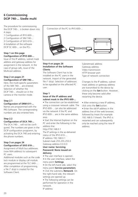
Connection of the PC to <strong>IP</strong>VS 600-...<br />
Step 4 on pages 26<br />
Installation of the Software<br />
Clients<br />
The Software Client has to be<br />
installed on the PC users in the<br />
network. Import of the generated<br />
file (*.dcip). Selection of addresses<br />
to be signalled on the affected PC<br />
user.<br />
Step 1<br />
Issue of the <strong>IP</strong> address and<br />
subnet mask in the <strong>IP</strong>VS 600-...<br />
• The connection can be established<br />
using a crossover network cable. The<br />
<strong>IP</strong>VS 600-... can also be addressed<br />
via the network if the PC and<br />
<strong>IP</strong>VS 600-... are in the same address<br />
area.<br />
• Start the Internet Explorer on the<br />
PC and enter the following in the<br />
address line:<br />
http://192.168.0.1<br />
The <strong>IP</strong> settings in the as-delivered<br />
status of the <strong>IP</strong>VS 610-...<br />
<strong>IP</strong> address 192.168.0.1<br />
Subnet mask 255.255.255.0<br />
Gateway address 0.0.0.0<br />
User name: Servicing<br />
Password: None issued on<br />
delivery<br />
• The user interface is opened..<br />
• In the user interface, select the<br />
menu point Settings.<br />
• On the left-hand side, select the<br />
menu point Service parameters.<br />
• Click the submenu Network. On<br />
the right-hand side, the relevant<br />
settings are opened up.<br />
• The following settings can be<br />
performed for operation in the<br />
network.<br />
<strong>IP</strong> address<br />
Subnetmask address<br />
Gateway address<br />
Video transmission<br />
HTTP browser port<br />
Type of network connection<br />
Changes to the <strong>IP</strong> address, subnet<br />
mask address or gateway address<br />
are transmitted to the device by<br />
clicking on the Set button. However,<br />
these only become valid after<br />
restarting the device.<br />
• After entering a new <strong>IP</strong> address,<br />
click onto the Set button.<br />
• Enter the old <strong>IP</strong> address in the<br />
address line of the web browser,<br />
followed by /reset (for example<br />
192.168.0.11/reset). The <strong>IP</strong>VS is<br />
restarted and can subsequently<br />
only be reached using the new <strong>IP</strong><br />
address.