Operating Manual - Winkhaus
Operating Manual - Winkhaus
Operating Manual - Winkhaus

Create successful ePaper yourself
Turn your PDF publications into a flip-book with our unique Google optimized e-Paper software.
<strong>Operating</strong> <strong>Manual</strong> EAV 25<br />
3.5 Access control system wireless remote control<br />
Aug. <strong>Winkhaus</strong> GmbH & Co. KG · Berkeser Str. 6 · D-98617 Meiningen · www.winkhaus.de<br />
Subject to technical changes<br />
Print-no. 250 020 1<br />
08/2009<br />
Prerequisites for installation:<br />
• To ensure the reliable performance, the position of the wireless receiver is of utmost<br />
importance for the received power.<br />
• Do not install it at or nearby sources of possible interference (e.g. EDP/high-performance<br />
power distributor).<br />
• To prevent manipulation of the receiver we recommend installing the receiver on<br />
the inner side of the door!<br />
3.5.1 Wireless remote control set<br />
Installation sequence:<br />
• Install the wireless receiver in a standard flush-type box on the inside.<br />
• Unless you use a switch or button beside the door; you will have to provide a flushtype<br />
box with a filler panel for the wireless receiver.<br />
+ NOTICE!<br />
If you use the flush-type box of the button, the box will have to be<br />
65 mm [2.559”] deep!<br />
DANGER! For safety reasons, you are not permitted to install it in a flushtype<br />
box with a 230 V switch or socket outlet!<br />
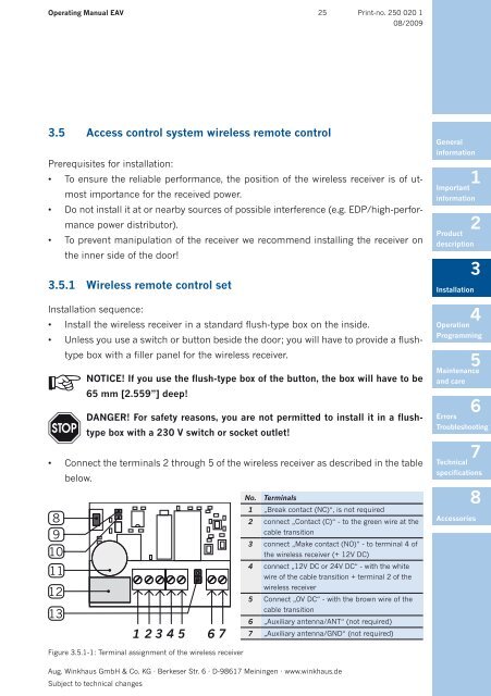
• Connect the terminals 2 through 5 of the wireless receiver as described in the table<br />
below.<br />
8<br />
9<br />
10<br />
11<br />
12<br />
13<br />
1 2 3 4 5 6 7<br />
Figure 3.5.1-1: Terminal assignment of the wireless receiver<br />
No. Terminals<br />
1 „Break contact (NC)“, is not required<br />
2 connect „Contact (C)“ - to the green wire at the<br />
cable transition<br />
3 connect „Make contact (NO)“ - to terminal 4 of<br />
the wireless receiver (+ 12V DC)<br />
4 connect „12V DC or 24V DC“ - with the white<br />
wire of the cable transition + terminal 2 of the<br />
wireless receiver<br />
5 Connect „0V DC“ - with the brown wire of the<br />
cable transition<br />
6 „Auxiliary antenna/ANT“ (not required)<br />
7 „Auxiliary antenna/GND“ (not required)<br />
General<br />
information<br />
1<br />
Important<br />
information<br />
Installation<br />
2<br />
Product<br />
description<br />
3<br />
4<br />
Operation<br />
Programming<br />
5<br />
Maintenance<br />
and care<br />
6<br />
Errors<br />
Troubleshooting<br />
7<br />
Technical<br />
specifications<br />
8<br />
Accessories