- Page 1 and 2: Pocket Guide to Flanges, Fittings,
- Page 3 and 4: equired to fit the nut. An oval rin
- Page 5 and 6: Acknowledgments, Page x Preface, Pa
- Page 7 and 8: "Im~L~_ZATLO R ~ORGE_A ~ Welding Ne
- Page 9 and 10: E E I- e-- E ~ o ~ N ~5 c- O e,- ~
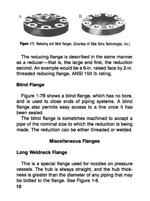
- Page 11 and 12: common in 150-1b and 300-1b classes
- Page 13: Slip-on Flange Lap Joint Flange Fig
- Page 17 and 18: Figure 1-10. Cutaway of an orifice
- Page 19 and 20: Accounting Records Good technical d
- Page 21 and 22: 16 l! ':l,i, :~! :l, :~t ' ' '~i, :
- Page 23 and 24: als control persons. Familiarize yo
- Page 25 and 26: Do not grease, spray, or clean bolt
- Page 27 and 28: 9 . Figure 1-15. Dimensional gauge
- Page 29 and 30: Table 1-3 Alloy Steel Stud Bolts fo
- Page 31 and 32: Table 1-5 Alloy Steel Stud Bolts fo
- Page 33 and 34: Table 1-7 Alloy Steel Stud Bolts fo
- Page 35 and 36: Table 1-9 Alloy Steel Stud Bolts fo
- Page 37 and 38: Table 1-11 Alloy Steel Stud Bolts f
- Page 39 and 40: Table 1-13 Alloy Steel Stud Bolts f
- Page 41 and 42: Table 1-15 Alloy Steel Stud Bolts f
- Page 43 and 44: uJ o0 Z O 03 03 0'3 o coco co ~ o c
- Page 45 and 46: 2 ANSI BUTTWELD FITTINGS ANSI buttw
- Page 47 and 48: Figure 2-2.90-degree elbows, long a
- Page 49 and 50: . . . . . 45 , ,~ + 9 ' 'i'i .~i"~;
- Page 51 and 52: Figure 2-5. 180-degree returns, lon
- Page 53 and 54: ' Tees Crosses C C @ ALj~ A A B Tee
- Page 55 and 56: Lap Joint Stub Ends The stub end is
- Page 57 and 58: Figure 2-13. Pipe saddle. (Courtesy
- Page 59 and 60: Large diameter fittings can be stor
- Page 61 and 62: Figure 2-17. Flat type and ridge ty
- Page 63 and 64: 59 S3ZI$ NNtl ~ ~!i~:~_~ ~= ~~ w 0
- Page 65 and 66:
the Olets are shown in the table, a
- Page 67 and 68:
threaded, socket weld, and buttweld
- Page 69 and 70:
Storing Olets All threaded sizes of
- Page 71 and 72:
Table 3-1 Pipe Chart (Courtesy of T
- Page 73 and 74:
Table 3.1 continued 3V2 4.000 5 10
- Page 75 and 76:
Table 3-1 continued 12 12.750 40 60
- Page 77 and 78:
Table 3-1 continued 26 26.000 28 28
- Page 79 and 80:
Seamless Pipe This type of pipe is
- Page 81 and 82:
Table 3-2 Bundling Schedule Nominal
- Page 83 and 84:
~+L ". ! ~RACK 8~ ~ ,,..__, .----+,
- Page 85 and 86:
5. Always measure pipe within tenth
- Page 87 and 88:
4 APi FLANGES The difference betwee
- Page 89 and 90:
New API Bore Sizes for Flanges and
- Page 91 and 92:
API Type 6B and 6BX Flanges 2,000-2
- Page 93 and 94:
Table 4-7 API Type 6BX Weldneck Fla
- Page 95 and 96:
Table 4-11 API Type 6BX Integral Fl
- Page 97 and 98:
x45 ,_1 -< ~§ 1/32 mox "qP'-" ~- O
- Page 99 and 100:
Bolt lengths have been calculated t
- Page 101 and 102:
s I S DETAIL I DETAIL 2 Figure 4-6.
- Page 103 and 104:
API Hubs and Clamps Figures 4-7 and
- Page 105 and 106:
wrench size required to fit the nut
- Page 107 and 108:
Table 4.21 BX Gaskets for API Type
- Page 109 and 110:
Table 5-1 Dimensions for Stainless
- Page 111 and 112:
T .......... 0 -~ ~ ---~ O.D. r---
- Page 113 and 114:
The most likely types of stainless
- Page 115 and 116:
' / k STRAIGHT TEES STRAIGHT CROSSE
- Page 117 and 118:
STUB ENDS--MSS SHORT LENGTHS TYPE C
- Page 119 and 120:
Table 5-2 Dimensions for Stainless
- Page 121 and 122:
Nominal P~pe Size ...... .... i/| .
- Page 123 and 124:
~ OM. I OUTSIDE LAP IPE DIAMETER Dl
- Page 125 and 126:
Table 5-3 continued SCHEDULE 80S Ex
- Page 127 and 128:
Table 5-4 Color Code Chart Type of
- Page 129 and 130:
AISI TYPE 302 303 303Se 304 308 309
- Page 131 and 132:
6 MISCELLANEOUS ITEMS There are sma
- Page 133 and 134:
Coupling Half Couplinll Reducer Cap
- Page 135 and 136:
Figure 6-6. Sub-tubing nipple, pup-
- Page 137 and 138:
Gaskets require proper storage meth
- Page 139 and 140:
I 7 PIPELINE PIGS Pipelines require
- Page 141 and 142:
Figure 7-2. Spherical pipeline pigs
- Page 143 and 144:
Figure 7-4B. Pipeline pig closures.
- Page 145 and 146:
The KnolDp Polly-Spt'~re through th
- Page 147 and 148:
The diameter of Polly-Pigs is usual
- Page 149 and 150:
STYLE m ! m CID TYPE RCC-SC (Red cr
- Page 151 and 152:
Z ~ ONNN~NbNN~NbNN~b~b ~ Z ~ ~ ~ ~
- Page 153 and 154:
8 MATERIALS HANDLING TIPS Tallying
- Page 155 and 156:
Figure 8-2. Engineer's tape and boa
- Page 157 and 158:
1 2 3 4 5 6 1. Purchase order numbe
- Page 160 and 161:
Vendor Data Invariably vendor data
- Page 162 and 163:
Brz BSE CI Cm CS Cu CW Chk Cpl CSC
- Page 164 and 165:
MM M&F Max Mfg Min Misc MRR MSS MTO
- Page 166 and 167:
Spl Sht Scrd Smls Spec bid 162 TI T
- Page 168 and 169:
27 cubic feet = 1 cubic yard 0.6213
- Page 170 and 171:
INDEX Abbreviations, piping, 149-15
- Page 172 and 173:
educing, 47-49 service, 48 side out
- Page 174 and 175:
pressures required for polly- piggi
- Page 176:
ABOUT THE AUTHOR R. R. Lee is the v