Use of MicroManipulator 6400 Probe Station - Login | Nanolab, UCLA
Use of MicroManipulator 6400 Probe Station - Login | Nanolab, UCLA
Use of MicroManipulator 6400 Probe Station - Login | Nanolab, UCLA

Create successful ePaper yourself
Turn your PDF publications into a flip-book with our unique Google optimized e-Paper software.
PREPARED BY:<br />
REVISED BY:<br />
Superusers:<br />
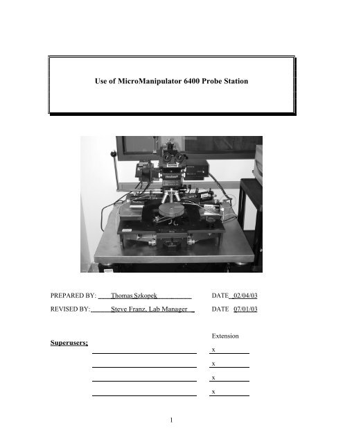
<strong>Use</strong> <strong>of</strong> <strong>MicroManipulator</strong> <strong>6400</strong> <strong>Probe</strong> <strong>Station</strong><br />
Thomas Szkopek DATE<br />
Steve Franz, Lab Manager<br />
1<br />
DATE<br />
Extension<br />
x<br />
x<br />
x<br />
x<br />
02/04/03<br />
07/01/03
1.0 SCOPE<br />
<strong>Use</strong> <strong>of</strong> M&M <strong>6400</strong> <strong>Probe</strong> <strong>Station</strong><br />
This document establishes the procedures for DC semiconductor device measurements<br />
using the HP4145B parameter analyzer and Micromanipulator probe station located in the<br />
<strong>UCLA</strong> nanolab.<br />
2.0 APPLICABLE DOCUMENTS<br />
Parameter Analyzer Logbook and Maintenance Logbook<br />
M & M <strong>Probe</strong> <strong>Station</strong> Instruction Manual<br />
HP 4145 Operation Manual<br />
3.0 MATERIALS AND EQUIPMENT<br />
HP4145B semiconductor parameter analyzer<br />
Micromanipulator <strong>6400</strong> manual probe station<br />
Low frequency probes.<br />
<strong>Probe</strong> tips, 0.007” or 0.002” diameter.<br />
Tweezers<br />
HP System Disk (Floppy)<br />
Data Disk (optional)<br />
4.0 GENERAL<br />
Measure only clean samples at the probe station. Exercise caution when moving probes or<br />
stage as the tips are very delicate.<br />
5.0 PROCESS PREPARATION<br />
System Power Up<br />
5.1.1 Verify the previous entry in the logbook does not indicate any problems<br />
Refer to Figures 1, 2, and 3 for location <strong>of</strong> switches, levers and knobs.<br />
5.1.2 Switch on the Micromanipulator translation stage by depressing the yellow<br />
power button. The power indication LED should illuminate red.<br />
5.1.3 Switch on the power to the stage vacuum pump located on the floor to the<br />
left <strong>of</strong> probe station.<br />
5.1.4 Rotate the microscope lamp power knob to desired brightness (usually a<br />
setting <strong>of</strong> 1 or 2 is bright enough).<br />
5.1.5 Ensure the HP4145B boot disk is in the disc drive <strong>of</strong> the HP4145B. Switch<br />
on the HP4145B with the LINE button.<br />
2
. 6.0 PROCEDURE<br />
6.1<br />
Wafer Loading and <strong>Probe</strong> Contact<br />
6.1.1 <strong>Use</strong> the lever to raise the probe table being careful not to collide the tips with<br />
the microscope objective. If necessary, move the probes out <strong>of</strong> the way<br />
first.<br />
6.1.2 Ensure that the micromanipulator stage is clean, free <strong>of</strong> debris and the stage<br />
vacuum is <strong>of</strong>f. Carefully load your substrate which must be clean and free<br />
from dirt, photoresist etc onto the stage with tweezers. Flip the vacuum<br />
switch located at the left side <strong>of</strong> the station to apply suction. Vacuum is not<br />
necessary for small substrate pieces. If a loud hissing noise is heard or your<br />
sample is not being held down tightly, reposition your sample on the chuck<br />
or clean the backside <strong>of</strong> your sample.<br />
6.1.3 There are 3 probe arms. Select the probes to be used and gently swing them<br />
into position under the microscope approximately where you want them.<br />
MAKE SURE THE TIPS ARE UP BEFORE DOING THIS. <strong>Probe</strong>s are<br />
magnetically held to the platen.<br />
6.1.4 Select the lowest magnifying objective, 2.5x (blue) to start.<br />
6.1.5 Lower the probe table carefully with the table lever, taking care that the<br />
probe tips do not make contact with your sample. You must depress the<br />
white button on the table lever in order to unlock it BEFORE lowering<br />
probe table.<br />
6.1.6 <strong>Use</strong> the thumbwheel knob below the eyepiece to adjust eyepiece separation<br />
to your eyes.<br />
6.1.7 Adjust the microscope focus and zoom (1x) to obtain a view <strong>of</strong> your sample<br />
with the largest field <strong>of</strong> view. The lateral microscope position can be<br />
adjusted with the large black knobs located on the translation rails. Move<br />
the probe arms on the table so that they are within view <strong>of</strong> the microscope.<br />
6.1.8 <strong>Use</strong> the stage control joystick to move your wafer sample and locate the<br />
desired device for testing. Depress the joystick for rapid stage movement.<br />
Stage rotation can be effected with the stage rotation knob.<br />
6.1.9 With the desired device in view, carefully adjust the fine lateral position <strong>of</strong><br />
the probe tips with the adjustment screws (assuming you have already done<br />
gross positioning). There are 3 screws (Fig 2): one for forward/backward,<br />
one for side to side and another for up down.<br />
6.1.10 Carefully lower the probe tips by the fine height adjustment screws<br />
(Up/Down in Fig 2) to make contact with your sample pads. Sample contact<br />
will be visible as a change in lateral motion <strong>of</strong> the probe tip. Increase<br />
magnification as needed using either the zoom knob or using a higher power<br />
objective. . Do not lower the tip height beyond what is needed<br />
to make contact.<br />
3
Note: Tips may now be simultaneously raised or lowered using the fine<br />
table height adjust knob on the right side <strong>of</strong> the stage (Fig 1).<br />
6.2<br />
6.3<br />
Parametric Analyzer Setup (Fig 3)<br />
6.2.1 Press the NEXT button under page control to advance the current page to<br />
the channel definition menu. <strong>Use</strong> the PREV button at any time to change or<br />
review page content.<br />
6.2.2 The measurement variables are assigned to 1 <strong>of</strong> 4 Source Monitor Units<br />
(SMU’s) and voltage sources on the channel definition page. Three predefined<br />
measurement modes can be selected: ß-trace, FET and DIODE. <strong>Use</strong><br />
the s<strong>of</strong>tkeys to select the desired mode. Each probe is labelled with the<br />
SMU to which it is connected (SMU1, SMU2 etc); use the s<strong>of</strong>tkey CHAN<br />
ASSIGN option to select the SMU’s as required by the probe arrangement<br />
for your device. Press the NEXT button to advance to the source setup<br />
page.<br />
6.2.3 <strong>Use</strong> the cursors to navigate the source parameter fields. <strong>Use</strong> the s<strong>of</strong>tkeys to<br />
select linear or logarithmic sweep. The start, stop, step parameters can be<br />
set with the numeric key pad and postfix multipliers, followed by the ENT<br />
key. Set the compliance values for maximum current or voltage to prevent<br />
possible damage to your device under test. Press the NEXT button to<br />
advance to the measurement and display mode setup page.<br />
6.2.4 The graphics mode is selected by default. <strong>Use</strong> the cursors to navigate the<br />
graphing parameter options. Select the desired variables to plot with the<br />
s<strong>of</strong>tkeys. Select the desired scale (linear or logarithmic) with the s<strong>of</strong>tkeys.<br />
<strong>Use</strong> the numeric key pad to enter the maximum and minimum plotting<br />
range. Press the NEXT button to advance to the graphics plot page.<br />
Parameter Measurement<br />
6.3.1 Press the SINGLE measurement button to perform a single measurement<br />
sweep. Continuous sweep can be selected with the REPEAT button. <strong>Use</strong><br />
the STOP button at any time to stop a measurement. The APPEND button<br />
can be used to continue an interrupted measurement sweep.<br />
6.3.2 <strong>Use</strong> the top s<strong>of</strong>tkey extension button to cycle through the s<strong>of</strong>tkey items<br />
accessible. <strong>Use</strong> the AUTOSCALE s<strong>of</strong>tkey option to scale your plot to<br />
your measured data. <strong>Use</strong> the MARKER s<strong>of</strong>tkey option to create a plot<br />
marker controlled by the marker dial.<br />
6.3.3 If the measurement data is noisy, use the SHORT, MED and LONG<br />
integration time buttons to adjust the number <strong>of</strong> measurement samples per<br />
plot point (0, 16 and 256 respectively).<br />
6.3.4 If another device is to be measured on the same wafer, stop all<br />
measurements. Raise the probe table with the fine table height adjustment<br />
knob; note the direction for raising the table. Adjust the stage position for<br />
the next device. Gently lower the probe table with the fine table height<br />
adjustment knob. <strong>Use</strong> the PREV button to revisit the settings <strong>of</strong> previous<br />
pages outlined in 6.2 onwards.<br />
4
6.4<br />
6.5<br />
Unloading Wafer<br />
6.4.1 Raise the probe tips from your sample with the fine (Up/Down) adjustment<br />
screws. Note the screw direction for raising the probe tips.<br />
Raise the probe table and microscope using first the fine table height adjust<br />
and then the table lever.<br />
6.4.2 Flip the stage vacuum switch <strong>of</strong>f. Carefully remove your sample with<br />
tweezers.<br />
6.4.3 If another wafer substrate is to be measured, proceed from step 6.1<br />
onwards.<br />
System Shutdown<br />
6.5.1 Once all measurements are complete and the sample is unloaded, press the<br />
LINE button on the HP4145B to switch the power <strong>of</strong>f.<br />
6.5.2 Rotate the microscope lamp power knob to switch the lamp <strong>of</strong>f. Make sure<br />
the probe table and microscope are in the up position.<br />
6.5.3 Switch <strong>of</strong>f the power to the vacuum pump.<br />
6.5.4 Depress the yellow power button to turn <strong>of</strong>f the Micromanipulator<br />
translation stage. The red power indication LED should slowly dim.<br />
6.5.5 Fill out a complete log book entry.<br />
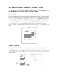
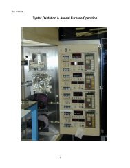
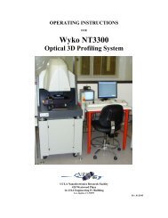
table lever<br />
lamp power<br />
stage vacuum switch<br />
stage rotation<br />
stage joystick<br />
5<br />
fine table height<br />
adjustment<br />
Fig 1. M & M <strong>Probe</strong> <strong>Station</strong> and Controls<br />
stage power
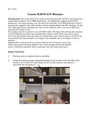
Fig 2. <strong>Probe</strong> arm and 3 fine adjust knobs<br />
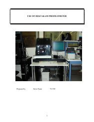
Fig 3. HP 4145 Parametric Analyzer<br />
6