Mask Submission Appendix - Login | Nanolab, UCLA
Mask Submission Appendix - Login | Nanolab, UCLA
Mask Submission Appendix - Login | Nanolab, UCLA

You also want an ePaper? Increase the reach of your titles
YUMPU automatically turns print PDFs into web optimized ePapers that Google loves.
<strong>Mask</strong> <strong>Submission</strong> <strong>Appendix</strong> (Latest Revision 4/1/08 by Ivan Alvarado)<br />
It is mandatory to read the mask submission appendix before submitting a mask to<br />
the NRF. Read the parts that are related to your own design.<br />
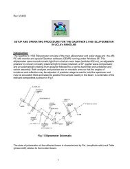
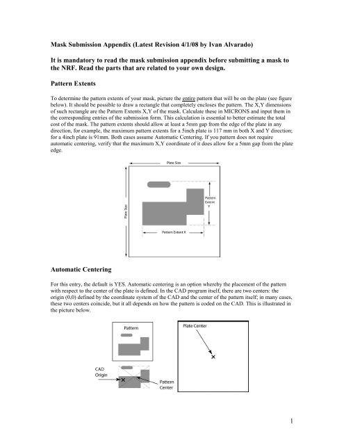
Pattern Extents<br />
To determine the pattern extents of your mask, picture the entire pattern that will be on the plate (see figure<br />
below). It should be possible to draw a rectangle that completely encloses the pattern. The X,Y dimensions<br />
of such rectangle are the Pattern Extents X,Y of the mask. Calculate these in MICRONS and input them in<br />
the corresponding entries of the submission form. This calculation is essential to better estimate the total<br />
cost of the mask. The pattern extents should allow at least a 5mm gap from the edge of the plate in any<br />
direction, for example, the maximum pattern extents for a 5inch plate is 117 mm in both X and Y direction;<br />
for a 4inch plate is 91mm. Both cases assume Automatic Centering. If you pattern does not require<br />
automatic centering, verify that the maximum X,Y coordinate of it does allow for a 5mm gap from the plate<br />
edge.<br />
Automatic Centering<br />
For this entry, the default is YES. Automatic centering is an option whereby the placement of the pattern<br />
with respect to the center of the plate is defined. In the CAD program itself, there are two centers: the<br />
origin (0,0) defined by the coordinate system of the CAD and the center of the pattern itself; in many cases,<br />
these two centers coincide, but it all depends on how the pattern is coded on the CAD. This is illustrated in<br />
the picture below.<br />
1
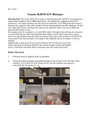
By choosing Automatic Centering YES, the pattern center will coincide with the center of the plate. For<br />
Automatic Centering NO, the origin defined in the CAD will coincide with the center of the plate. See<br />
picture below. The default is YES as we found that this is what it is more common.<br />
<strong>Mask</strong> Polarity<br />
<strong>Mask</strong> Polarity Noninverted, the digitized areas are openings. The figure below shows the effect of each<br />
selection. There is no default for this entry and so the user must specify what polarity is desired. Notice that<br />
in the Inverted case, a frame enclosing your entire pattern must be defined (See the Inverted Requirement<br />
section below for more details). DO NOT use the terms Clear Field, Dark Field, Bright Field, Light Field<br />
etc. when referring to mask polarity (see explanation below).<br />
2
Clear Field or Dark Field (?)<br />
The terms Clear Field, Dark Field, Bright Field, Light Field, etc. are ambiguous when they are used to<br />
determine the Polarity of the <strong>Mask</strong>. Those terms are frequently used to describe the general “appearance”<br />
of the mask when it is visually inspected against a light source; some mask shops use those terms to<br />
determine which resist tone is to be used on their plates (which is NOT the case of our mask shop).<br />
However, a Clear Field <strong>Mask</strong> is not necessarily Inverted and, by the same token, a Dark Field <strong>Mask</strong> is not<br />
necessarily Noninverted.<br />
Please use the terms Inverted or Noninverted for <strong>Mask</strong> Polarity whenever submitting a mask order or<br />
consulting about mask making with the NRF <strong>Mask</strong>shop staff. The section above properly explains how to<br />
determine whether your mask will be Inverted or Noninverted.<br />
Exporting CIF From L-Edit:<br />
1. Open your_layout_file.tdb.<br />
2. Open the master cell.<br />
3. Create a new file, save it as mask_name.tdb.<br />
4. Hit I key to instance your master cell (select your_layout_file.tdb on the “file” pull down menu).<br />
5. Go to File →Export <strong>Mask</strong> Data, and save mask file as your_last_name_mask_name.cif.<br />
6. Accept the message that no fabrication cell has been designated.<br />
7. Save the exported cif file onto a jump drive or CD.<br />
Un-flattened Files in CIF format (CIF Files with more than one cell)<br />
Some mask files are rejected because the CIF file is not flat or “un-flattened”. What this means is that when<br />
running the CIF file through the conversion software, we detect that there are more than one cell present in<br />
the file. This is mostly due to the fact that users code their masks using cell hierarchies; this hierarchy is<br />
reflected in the number of different cells on the file and how they are recalled in the mask file. Since it is<br />
impossible for us to determine which one is the lead cell in the hierarchy, we require all the CIF files to be<br />
flattened, i.e. the cell hierarchy must be completely removed so that the file is “flat”. If your file is returned<br />
because it is not flattened, follow this procedure (there are many ways to flatten the file; the procedure<br />
below is a long but very sure way to do it using L-Edit):<br />
1. Import CIF File on L-Edit.<br />
2. Open the cell that you want to be on the mask.<br />
3. Select the entire pattern and hit the UNGROUP button until there is nothing else to ungroup. This<br />
effectively removes the cell hierarchy.<br />
4. With the whole pattern still selected, hit the GROUP button and create a new cell.<br />
5. Open the cell you just created.<br />
6. Select Menu/Save Cell to File...<br />
7. Rename Cell File. A new L-Edit file containing ONLY this cell will be created.<br />
8. Close L-Edit. Do not save this file unless you want the cell you just ungrouped to be remain like<br />
that.<br />
9. Open the L-Edit file under which you saved the Cell File<br />
10. On L-Edit Select Cell/Fabricate<br />
11. Select the cell. There should be only ONE cell in the menu. If there is more than one cell, STOP<br />
and redo this procedure again; you made a mistake somewhere.<br />
12. Export Cell into CIF<br />
13. Submit the new CIF file to the <strong>Nanolab</strong><br />
3
If you are NOT using L-Edit and you are submitting your file in CIF, please follow a similar procedure in<br />
your own CAD. The end CIF file must contain only ONE cell, otherwise the file will be rejected. If you<br />
have questions about L-Edit or the CAD program that you are using, please consult the manual of that<br />
program or the vendor.<br />
Inverted (Clear Field) <strong>Mask</strong> Layout Requirements:<br />
1. All clear-field masks require a 10 micron wide border surrounding the desired layout.<br />
2. There should be at least a 25 micron gap between the nearest structure and the edge of the border.<br />
3. All area outside of the designated border will remain dark/chrome.<br />
Potential Issues When Using Wires in <strong>Mask</strong> Layouts:<br />
1. Wires will have rounded-over ends when converted to .lic file format.<br />
2. Shorting may result if wires are not overlapped in original drawing format.<br />
Pointers on Autocad DXF files<br />
1. Save DXF files as either Autocad Rev 12 or 14 versions. Do not save in Autocad 2000 or higher<br />
versions.<br />
2. Avoid using layer 0 on Autocad.<br />
3. Specify the design units (mm, in, cm, etc) in which the DXF file was coded.<br />
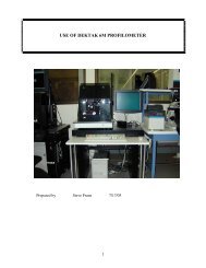
4. The Line command is not supported. Use box or polyline instead (See example below):<br />
Autocad Lines<br />
(Wrong Way)<br />
Incorrect<br />
Original Wire<br />
Connected Wires<br />
Correct<br />
Converted Wire<br />
Shorted Wires<br />
Autocad Box or Closed Polyline<br />
(Right Way)<br />
4
In the figure above it is desired to have a bridge connecting the two pads. Lines used to define this<br />
bridge will be ignored by the DWL converter. Use a full box or a closed polyline to define the<br />
bridge.<br />
5. The DWL converter does not support HATCH. When a polygon is closed, the converter assumes<br />
that it is filled on the inside and, thus, it is not necessary to hatch it. If this filling is not desired,<br />
specify that the layout is inverted on the submission form.<br />
6. If the HATCH operation is needed for a polygon boolean operation (such as subtraction or XOR)<br />
in order to create an opening or window inside a filled polygon, look for alternatives in Autocad<br />
itself which will produce the same effect without having to instance the HATCH operation. See<br />
example below:<br />
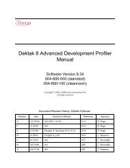
This is an alternative to the HATCH operation in Autocad: It is desired to have an array of chrome<br />
rectangles with a circular window in between. This is typically done in Autocad by drawing a<br />
rectangle and a circle first and then by applying the HATCH operation which will exclude the<br />
circle inside the rectangle. Once that’s done, the mask will be then ordered as “inverted”.<br />
Digitized<br />
Area<br />
Clear<br />
Since the HATCH operation is not supported by the converter software, what can be done is to<br />
draw a circle and then frame it using rectangles around it. Then specify the mask as “noninverted”<br />
when submitting the form.<br />
5
Digitized<br />
Areas<br />
7. Some Autocad files which already contain the HATCH operation can still be repaired by the<br />
nanolab staff. Please consult directly to the nanolab staff. Be aware that there are cases in which<br />
there is no practical way to repair the file so that the mask will have to be remade on Autocad in a<br />
way that the HATCH operation is avoided.<br />
8. When using multiple layers on Autocad, the label names must not contain any special characters<br />
or spaces.<br />
Submitting <strong>Mask</strong> Layouts to <strong>UCLA</strong> NRF:<br />
1. Complete a NRF <strong>Mask</strong> Fabrication <strong>Submission</strong> Form for each mask layer. Make sure that you<br />
have the latest version of the submission form.<br />
2. <strong>Mask</strong> filenames may not contain spaces or any other special characters. Underscore bar and dashes<br />
are OK.<br />
3. Bring the submission form(s) and cif file(s) to the <strong>Nanolab</strong> office. You can also email the files to<br />
maskshop@seas.ucla.edu, Ivan Alvarado (ialva@ee.ucla.edu), or Joe Zendejas<br />
(zendejas@ee.ucla.edu)<br />
Requesting a Quote for a <strong>Mask</strong><br />
In the lower right side of the submission form, an estimated cost of the mask will be displayed.<br />
This estimation depends on the Pattern Extents X,Y declared on the submission form. If properly done by<br />
the user, this cost estimate is fairly accurate (see Pattern Extents section above). This is NOT a quote in the<br />
strict sense, it is a cost estimate. Be aware that the <strong>Nanolab</strong> is not responsible for an improper calculation of<br />
the pattern extents and will send an invoice according to the real Pattern Extents shown in the mask after<br />
exposure.<br />
<strong>Mask</strong> Charges<br />
Clear<br />
• <strong>Nanolab</strong> Users (either <strong>UCLA</strong> or Non<strong>UCLA</strong>): If you have a <strong>UCLA</strong> <strong>Nanolab</strong> badge, write your<br />
badge number on the corresponding submission form entry (Badge # / Recharge ID / PO #) and<br />
specify that it is a nanolab badge number. Your nanolab account will be automatically charged.<br />
• <strong>UCLA</strong> customers that are NOT nanolab users: Provide account number or recharge ID.<br />
• UC System customers that are NOT nanolab users: Provide UC account number and<br />
administrative contact person in charge of that account.<br />
• Other customers (Non-UC system academic or industry that are NOT nanolab users): Provide PO<br />
number and forward it along with mask submission form.<br />
6
<strong>Mask</strong> Pick Up and Inspection<br />
1. The mask can be picked up from the mask pick up table located to the left as you enter the <strong>Mask</strong><br />
Writer room. Outside customers will get their mask shipped by the carrier of their choice at an<br />
extra charge. Provide account number for carrier, if available.<br />
2. It is the user’s responsibility to inspect the mask for errors immediately after receiving it. If there<br />
is any error on our side, we will remake the mask at no extra charge. This policy is void if the<br />
mask has already been used on the aligner or more than five days have passed after mask pickup.<br />
7