Wyko NT3300 Optical 3D Profiling System - Login | Nanolab, UCLA
Wyko NT3300 Optical 3D Profiling System - Login | Nanolab, UCLA
Wyko NT3300 Optical 3D Profiling System - Login | Nanolab, UCLA

You also want an ePaper? Increase the reach of your titles
YUMPU automatically turns print PDFs into web optimized ePapers that Google loves.
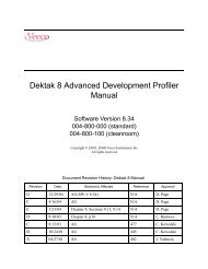
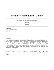
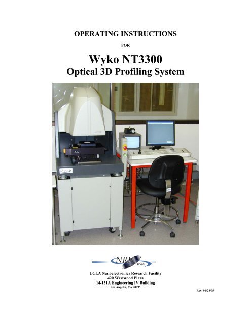
OPERATING INSTRUCTIONS<br />
FOR<br />
<strong>Wyko</strong> <strong>NT3300</strong><br />
<strong>Optical</strong> <strong>3D</strong> <strong>Profiling</strong> <strong>System</strong><br />
<strong>UCLA</strong> Nanoelectronics Research Facility<br />
420 Westwood Plaza<br />
14-131A Engineering IV Building<br />
Los Angeles, CA 90095<br />
Rev. 01/28/05
Primary Contacts: Email: Extension:<br />
Steve Franz franz@nanolab.ucla.edu ×68923<br />
Joe Zendejas zendejas@nanolab.ucla.edu ×65528<br />
Superusers: Email: Extension:<br />
I. Introduction:<br />
The automated <strong>Wyko</strong> <strong>NT3300</strong> is a system intended for measuring a wide variety of surfaces<br />
and samples, from optical-quality glass to microactuators. The <strong>Wyko</strong> is a relatively safe and<br />
simple machine that can provide measurements for all types of samples in great detail. In<br />
this procedure you will find all the instructions necessary to successfully acquire and<br />
interpret your measured data.<br />
<strong>System</strong><br />
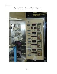
The automated <strong>Wyko</strong> <strong>NT3300</strong> system consists of two parts, an operator control station and a<br />
motorized sample station (figure on the front cover). The sample station houses the optical<br />
lenses, translation motors, and computer. The operator control tray shown in Fig. 1 has a<br />
joystick for controlling the x-y motorized stage and the motorized microscope head tilt. A<br />
centrally located control knob is used for the z-axis motorized focusing of the microscope<br />
head.<br />
Tip/Tilt Button<br />
Stage Control Joystick<br />
Z-Axis<br />
Control<br />
Keyboard<br />
Fast Button<br />
(Z-Axis control)<br />
Figure 1. Operator Control Tray<br />
Trackball<br />
Grounding Strap<br />
Connectors
VSI Measurements (160nm < Step height)<br />
Vertical Scanning Interferometry (VSI) uses the interference of light to map the surface<br />
of your sample. VSI is used for relatively rough surfaces (Ra greater than 0.1 µm) or<br />
surfaces with discontinuities or steps greater than 160 nm (λ/4). In VSI mode, the optics<br />
physically scan through the focus of the objective while obtaining “snapshots”, called<br />
frames, from the camera inside the Integrated Optics Assembly (IOA). These frames are<br />
used to reconstruct a map of the surfaces of the sample.<br />
PSI Measurements (Step height < 160nm)<br />
Phase Shifting Interferometry (PSI) uses the interference of light to produce information<br />
on the surface of a sample. PSI is used for extremely smooth samples like mirrors or<br />
optics. In PSI mode, a piezoelectric transducer (PZT) within the IOA head precisely<br />
shifts the interference pattern six times; each shift is captured to produce one frame of<br />
data. These frames are then reconstructed to form a topographical map of the measured<br />
surface.<br />
II. Starting the <strong>Wyko</strong>:<br />
1. Check the logbook to verify that there are no documented problems with the <strong>Wyko</strong>.<br />
2. Make sure to sign the logbook BEFORE every use.<br />
3. If the instrument is already ON, you may only need to turn ON the CRT monitor.<br />
Otherwise, to turn ON the <strong>Wyko</strong>, gently pull the red emergency-power-down switch<br />
until it pops out, and then press the green lighted Start button. Next, turn on the CPU<br />
located behind the cabinet door and also turn ON the CRT screen.<br />
4. Start the Vision 3.43 software.<br />
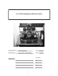
5. If the <strong>Wyko</strong> has just been turned ON, it will need to be recalibrated with the<br />
appropriate calibration standard (Fig. 2).<br />
A B<br />
PSI calibration standard VSI calibration standard<br />
Fig 2. Calibration Standards
III. VSI – Mode (Vertical Scanning Interferometry):<br />
VSI – Calibration:<br />
1. Select the MEASUREMENT OPTIONS icon from the toolbar.<br />
2. Select the INTENSITY box from the Measurement Options window. Arrange both<br />
windows side by side.<br />
3. Select VSI from the measurement type box and verify the following settings:<br />
Resolution = Full<br />
Objective = 5X<br />
FOV = 1.0X<br />
4. Raise the objective by turning the “Z-Axis” control knob clockwise while holding<br />
down the “Fast” button.<br />
5. Place the VSI calibration sample (Fig. 2B) on the stage.<br />
6. Using the Intensity window, setup the hardware for coarse focusing by going under<br />
HARDWARE →FILTER → PSI LOW MAG.<br />
7. Focus on the edge of the glass by slowly lowering the objective (You may need to<br />
translate the stage to locate this edge). DO NOT allow the objective to contact any<br />
surface.<br />
8. Adjust the intensity as needed to avoid saturation using the slidebar (saturation is<br />
indicated by red fringes). Once you have focused on the edge of the glass, find the<br />
best focus at the TOP of the feature/step, dark fringes should now be visible on this<br />
surface.<br />
9. Hold down the “Tilt” button and use the “Tilt and Tip” knobs to orient 3-4 fringes<br />
perpendicular to the step.<br />
10. Now setup the hardware for the final focusing by going under<br />
HARDWARE →FILTER → VSI, then readjust your final focus and intensity. The<br />
intensity should be set to just below the saturation limit of the CCD camera.<br />
11. Select the CALIBRATE box from the Measurement Options window.<br />
12. Select the AUTO CALIBRATE option.<br />
13. Type in the STEP HEIGHT VALUE that is written on the calibration standard<br />
(9.898 µm) then press OK and wait for the <strong>Wyko</strong> to finish calibrating.<br />
14. Select OK to complete the calibration.<br />
15. Repeat steps 6-13 to calibrate any remaining objectives that will be used.<br />
16. When calibration is complete, raise the objective and carefully remove the calibration<br />
standard and place it back into its container.<br />
VSI – Measurements:<br />
1. Place your sample in the center of the table. If your sample is small and requires<br />
stabilization, turn on the vacuum located on the floor and verify that the switchbox<br />
located on top of the CRT monitor is set to position “A”<br />
2. If the Measurements Options window isn’t already open, open it by clicking on the<br />
MEASUREMENT OPTIONS icon from the toolbar.
3. Select the INTENSITY box from the Measurement Options window. Arrange both<br />
windows side by side.<br />
4. Select VSI from the measurement type box and set the following settings to your<br />
desired field of view. (The field of view for several optics combinations are in Table 1)<br />
Resolution =<br />
Objective =<br />
FOV =<br />
5. Using the Intensity window, setup the hardware for coarse focusing by going under<br />
HARDWARE →FILTER → PSI LOW MAG.<br />
6. Focus on your sample by carefully lowering the objective. DO NOT allow the<br />
objective to contact any surface.<br />
7. Adjust the intensity as needed to avoid saturation using the slidebar. Once you find<br />
the best focus at the TOP of the feature/step, dark fringes should now be visible on<br />
this surface.<br />
8. Hold down the “Tilt” button and use the “Tilt and Tip” knobs to orient 3-4 fringes<br />
perpendicular to the step.<br />
9. Now setup the hardware for the final focusing by going under<br />
HARDWARE →FILTER → VSI, then readjust your final focus and intensity.<br />
10. After you have found the best focus and intensity, click on the VSI Options tab in<br />
order to adjust additional parameters such as the following:<br />
Speed of Measurement =<br />
Back scan =<br />
Length of Scan =<br />
Modulation Threshold =<br />
11. After setting all options, select OK from the Measurement Options window.<br />
12. Close the intensity window.<br />
13. To measure your sample, Select NEW.
IV. PSI – Mode (Phase Shifting Interferometry):<br />
PSI – Calibration:<br />
1. Select the MEASUREMENT OPTIONS icon from the toolbar.<br />
2. Select the INTENSITY box from the Measurement Options window. Arrange both<br />
windows side by side.<br />
3. Select PSI from the measurement type box and verify the following settings:<br />
Resolution = Full<br />
Objective = 5X<br />
FOV = 1.0X<br />
4. Raise the objective by turning the “Z-Axis” control knob clockwise while holding<br />
down the “Fast” button.<br />
5. Place the PSI calibration sample (Fig. 2) on the stage.<br />
6. Using the Intensity window, setup the hardware for coarse focusing by going under<br />
HARDWARE →FILTER → PSI LOW MAG.<br />
7. Focus on the edge of the mirror by slowly lowering the objective (You may need to<br />
translate the stage to locate this edge). DO NOT allow the objective to contact any<br />
surface.<br />
8. Adjust the intensity as needed to avoid saturation using the slidebar (saturation is<br />
indicated by red fringes). After focusing on the edge of the mirror, change the<br />
objective to 20X and find the best focus on the mirrors surface. Dark fringes should<br />
now be visible on this surface.<br />
9. Hold down the “Tilt” button and use the “Tilt and Tip” knobs to display 3-4 fringes.<br />
10. Now setup the hardware for the final focusing by going under<br />
HARDWARE →FILTER → PSI HIGH MAG, then readjust your final focus and<br />
intensity. The intensity should be set to just below the saturation limit of the CCD<br />
camera.<br />
11. Select the CALIBRATE box from the Measurement Options window.<br />
12. Select the AUTO CALIBRATE option.<br />
13. Select OK to complete the calibration.<br />
14. To accept the new calibration number, Select OK.<br />
15. Repeat steps 6-13 to calibrate any remaining objectives that will be used.<br />
16. When calibration is complete, raise the objective and carefully remove the calibration<br />
standard and place it back into its container.<br />
PSI – Measurements:<br />
1. Place your sample in the center of the table. If your sample is small and requires<br />
stabilization, turn on the vacuum located on the floor and verify that the switchbox<br />
located on top of the CRT monitor is set to position “A”<br />
2. If the Measurements Options window isn’t already open, open it by clicking on the<br />
MEASUREMENT OPTIONS icon from the toolbar.
3. Select the INTENSITY box from the Measurement Options window. Arrange both<br />
windows side by side.<br />
4. Select PSI from the measurement type box and set the following settings to your<br />
desired field of view. (The field of view for several optics combinations are in Table 1)<br />
Resolution = Full<br />
Objective = 5X<br />
FOV = 1.0X<br />
6. Using the Intensity window, setup the hardware for coarse focusing by going under<br />
HARDWARE →FILTER → PSI LOW MAG.<br />
7. Focus onto the edge of your sample by slowly lowering the objective (You may need<br />
to translate the stage to locate this edge). DO NOT allow the objective to contact any<br />
surface.<br />
8. Adjust the intensity as needed to avoid saturation using the slidebar (saturation is<br />
indicated by red fringes). After focusing on the edge of the mirror, change the<br />
objective to 20X and find the best focus on the surface. Dark fringes should now be<br />
visible on this surface.<br />
9. Hold down the “Tilt” button and use the “Tilt and Tip” knobs to display 3-4 fringes.<br />
10. Now setup the hardware for the final focusing by going under<br />
HARDWARE →FILTER → PSI HIGH MAG, then readjust your final focus and<br />
intensity. The intensity should be set to just below the saturation limit of the CCD<br />
camera.<br />
11. Change any PSI Options: at this time. For multiple measurements, under Averaging<br />
check the ON box. For Modulation Threshold (see definitions).<br />
11. After setting all options, Select OK from the Measurement Options window.<br />
12. Close the intensity window.<br />
13. To measure your sample, Select NEW.<br />
Analyzing your data<br />
In order the analyze your measurement data to return particular results about the test part,<br />
several display analysis options are available. The following procedures include the<br />
commands available on the Analysis menu.<br />
2D Display<br />
2D Analysis displays profile slices taken from the surface height data. You can adjust the<br />
locations and size of the region from which the slices are taken. To access the 2D Plot<br />
choose ANALYSIS → PROCESSED → 2D PROFILE, by choosing<br />
ANALYSIS → OTHER → OPTIONS → 2D PLOT.<br />
<strong>3D</strong> Plot<br />
<strong>3D</strong> Plot will create a 3-dimensional rendering of the surface area. Choose<br />
ANALYSIS → PROCESSED → <strong>3D</strong>. Right click on the graphic display to access plot<br />
and analysis options. These options will allow you to change the view angle, highlights,<br />
shading and/or to add perspectives to the plot.
IV. Stitching<br />
Stitching is an option that will allow for you to measure samples that are larger than a<br />
single field of view. Several measurements are taken and “stitched” together to form one<br />
dataset. Stitching properties are found in the Stitching tab in the measurements options<br />
window.<br />
1. To use stitching, select the Enable Stitching check box.<br />
2. Select the desired Starting Options<br />
Use Current Location: Allows you to set the measurement location before each<br />
measurement.<br />
Use Fixed Location: Will take a measurement at the same location each time.<br />
(This location is set by clicking the Set Start button, then<br />
moving the stage to the desired start location and clicking<br />
OK once again.<br />
3. Set the desired area to be measured using the Stitching Dimensions box. You may<br />
either enter the desired dimensions or you may train the <strong>Wyko</strong> by marking the<br />
measurement boundaries.<br />
4. To verify your dimensions are correct, click Test. Click OK to continue through all<br />
four corners of your desired area to be measured. Click Finish when done.<br />
5. You may have to re-enter or re-Teach the dimensions of your die, if any part of the<br />
measurement area was outside the corners of the test pattern.<br />
IV. Turning off the <strong>Wyko</strong><br />
If you will not be using the <strong>Wyko</strong> within the next hour or the time is after 5pm, please<br />
shut down the machine as follows.<br />
1. Close <strong>Wyko</strong> Vision 3.22.<br />
2. Close windows XP by selecting Start>>Shutdown.<br />
3. Turn off the monitors.<br />
4. Turn off the power to the main system by pushing in the main power switch.<br />
IV. Measurements Tips<br />
1. Check the limitations and resolution section of the reference page to determine which<br />
measurement is best for your sample.<br />
2. Transparent materials (i.e. PDMS, PMMA, Parylene, etc.) must be placed on top of a<br />
reflective material (i.e. wafer, glass with metal, mirror, etc.)<br />
3. The limitations for transparent materials, i.e. Silicon dioxide and Silicon Nitride, are a<br />
minimum of 2 µm for measuring the step height.<br />
Trouble Shooting<br />
1. If the tilt head becomes stuck and will not tilt in any direction, the entire system<br />
must be reset, including the power reset switch located in the back of the machine.
Download Veeco Vision 3.43- www.nanolab.ucla.edu/downloads/vision.zip