USE OF DEKTAK 6M PROFILOMETER - Login | Nanolab, UCLA
USE OF DEKTAK 6M PROFILOMETER - Login | Nanolab, UCLA
USE OF DEKTAK 6M PROFILOMETER - Login | Nanolab, UCLA

Create successful ePaper yourself
Turn your PDF publications into a flip-book with our unique Google optimized e-Paper software.
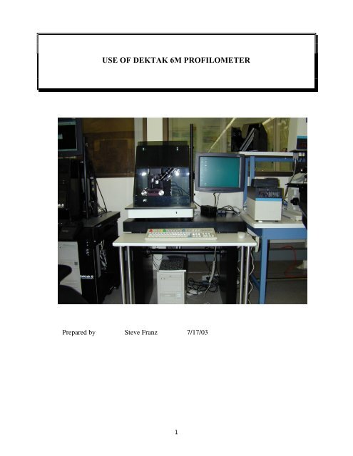
<strong>USE</strong> <strong>OF</strong> <strong>DEKTAK</strong> <strong>6M</strong> PR<strong>OF</strong>ILOMETER<br />
Prepared by Steve Franz 7/17/03<br />
1
Dektak <strong>6M</strong> Profilometer<br />
Introduction:<br />
This spec is an abbreviated procedure on how to operate the Dektak <strong>6M</strong> profilometer located in<br />
<strong>UCLA</strong>'s NRF. A more complete manual is available in pdf format on the Dektak 6 computer (C<br />
drive->Dektak->Docs->Dektak 6) and online. In most cases results can be achieved in more than<br />
one way (eg pull down menus or keyboard commands or icons etc). See full manual for more<br />
details and explanations. Also note that a more capable and similar looking machine, the Dektak<br />
8, is also available. For quick scans and ease of use where stage programmability is not needed,<br />
the Dektak <strong>6M</strong> may be a better choice.<br />
Operating Procedure:<br />
1 Check the log book to verify the last user had no problems.<br />
2 The Dektak <strong>6M</strong> and its computer are usually left on.<br />
a If this is the case, move the mouse to activate the LCD screen. When the<br />
Windows desktop is visible, maximize the D6 program following standard<br />
Windows procedures. This will return you to either the Sample Positioning<br />
window, data window or scan routine window.<br />
b If this is not the case, turn on the Dektak power located to the right of the machine<br />
on the back of the power rack (a bank of LEDs is located on the rack front). Turn<br />
on the computer power located below the Dektak table. If a network login is<br />
requested, double-click the D6 Manual icon to boot up the program. After a<br />
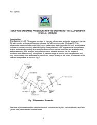
minute or two, the following screen should be seen. Click on the Sample<br />
Positioning Icon (arrow) to bring up the Sample Viewing window.<br />
Fig 1. Main Measurement Screen<br />
2
3 Open the chamber door and verify that the tower and stylus are in the full up position. If<br />
not, raise the stylus and tower by clicking on the<br />
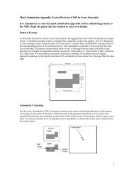
4 Manually move the stage towards you by turning the right stage knob counterclockwise<br />
(see Fig 2).<br />
Fig 2. Wafer stage and controls for Dektak <strong>6M</strong>.<br />
5 Position your sample in the center of the stage. Step to be measured should run<br />
horizontally ie left to right in Fig 2.<br />
Note that sample scanning is done by moving the stage from the rear to the front .<br />
However, this image is rotated on the LCD screen and the stage appears to move from<br />
right to left. You must take this into account when you load your sample.<br />
6 Manually move the stage using the x, y and theta knobs to position your sample under the<br />
probe tip.<br />
7 Making sure that your sample is under the stylus, lower the tower by clicking on the<br />
tower down and null icon .<br />
8 Adjust the lighting by either increasing or decreasing the intensity.<br />
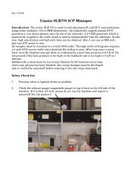
9 Make sure the stylus is NOT touching your sample. Adjust focus by turning the lower<br />
focus ring and adjust magnification by adjusting the upper (numbered) focus ring (Fig<br />
3). Magnification may be adjusted from 70 to 280X. Note: Stylus may be raised and<br />
lowered by pressing the yellow F3 key on the keyboard.<br />
3
Figure 3. Magnification and focus adjust<br />
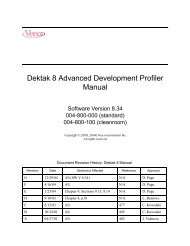
10 The location where the probe tip will touch your sample is given by the center of the<br />
reticle mark (see below). You will want to position your sample so that the location to be<br />
probed coincides with the reticle center.<br />
Note: If there is misalignment of the reticle mark, see the full procedure in the Dektak<br />
<strong>6M</strong> manual to correct.<br />
Reticle alignment mark<br />
11 Most likely you will want to make some fine adjustments on stage position and rotation.<br />
Proceed as in step 11 WITH THE STYLUS STILL UP.<br />
12 Once the sample is properly positioned under the stylus with the image in focus at the<br />
desired magnification, close the lid on the enclosure and go to the Scan Data Routine to<br />
setup the scan parameters. Click on the scan routine icon to enter this mode.<br />
Note 1: Refer to Dektak <strong>6M</strong> manual for setting up Automated Routines which is a<br />
sequence of single scans.<br />
4
13 The scan data window should appear on the LCD as shown below.<br />
14 Click on the SCAN PARAMETERS button and fill in the white blanks below:<br />
SCAN ID: You can leave this blank.<br />
Scan Length: This is the length of the desired scan in microns and must be from 50-<br />
30,000.<br />
Duration: This is the length of time it takes to complete an entire scan. This number<br />
must be between 3-100 seconds for a maximum of 30,000 data points per scan. Select a<br />
longer duration for large scan lengths or very fine surface roughness where high<br />
horizontal resolution is required. For most users a 10-30 second duration is a good start.<br />
Resolution: This is the horizontal resolution expressed in microns per sample so that a<br />
smaller number gives a higher resolution. Since the total number of points sampled is<br />
fixed, the resolution is related to the scan length and scan duration.<br />
5
Stylus Force: This is the force or effective weight of the stylus in mg. The range is 1.0 to<br />
15 mg. For very soft films or high aspect ratio structures using a nanotip, this number<br />
should be lowered. For the average sample, 15 mg is a good selection.<br />
Measurement Range: The available vertical resolution depends upon the measurement<br />
range selected. When measuring extremely fine geometries, use the most sensitive range<br />
(65 Kang) to get a vertical resolution of 1 Ang. For general applications, the 10 Ang<br />
vertical resolution of the 655 KAng range is usually adequate. When measuring thick<br />
films or very rough or curved surfaces, select the 2620 KAng range with 40 Ang<br />
resolution. Finally for very deep or rough structures the 1 mm range may be chosen.<br />
Profile: Valleys should be used where the area to be measured is below the surface since<br />
90% of the measurement range is provided below the zero. Hills provides 90% above the<br />
zero (as for measuring mesas for example) and hills and valleys provides 50% above and<br />
below the zero line. This is the most commonly used mode (except for the calibration<br />
sample). Click the appropriate profile button to select the desired mode.<br />
15 Click OK to exit the Scan Parameters Dialog Box.<br />
16 Click the Display Parameters button in the Scan Routine Window. A Dialog box should<br />
appear as below:<br />
17 If you want the software leveling to be automatic, check the automatic leveling box and<br />
choose a cursor width (20-50 microns is a good start). You must also know the cursor<br />
position, which can be obtained from the data window. Enter these numbers in the cursor<br />
positions box for both the R (reference) cursor and M (measurement) cursor. If you are<br />
unsure of how to do this, uncheck the automatic leveling and level manually as described<br />
below.<br />
18 Choose automatic ranging unless you want to manually set the vertical range of the<br />
graph. Click OK to exit the Display Parameters Box.<br />
19 If Data Processing filtering is desired, see Dektak <strong>6M</strong> manual.<br />
20 Click on the “scan” icon to initiate the scan.<br />
21 Assuming the Graphics & Video is selected , the stylus should automatically lower<br />
to the set location and the stage should begin moving. A video image of the stylus as well<br />
as a data screen should be displayed. When the scan is completed, the stylus lifts up, and<br />
6
the stage returns to where the scan originated. A data plot screen similar to below should<br />
be seen on the LCD monitor.<br />
22 In the example above, the plot is obviously not level and so manual leveling needs to be<br />
done. To do so:<br />
A Set the default cursor bandwidth (Plot-->Default Bands) from the pull-down<br />
menu.<br />
B Move the R cursor by using the mouse and clicking to grab and drag the cursor to<br />
one of the reference positions to be leveled. Alternately you can select the R<br />
button (bottom right) and click the appropriate arrow button.<br />
C Similarly, move the M cursor to the 2 nd leveling location. Try to keep the cursors<br />
as far apart as possible for best results.<br />
D Level the plot from the pull-down menu ( Plot _--->Level).<br />
Note 1: If automatic leveling was selected in the Display Parameters Box (step 17) AND<br />
BOTH cursors were properly set, manual leveling should not be necessary.<br />
Note 2: If the out-of-level is very severe such that manual leveling still does not produce<br />
an acceptable trace, mechanical leveling may be necessary and is covered later in the D6<br />
manual.<br />
7
23 The zero point of the trace for this plot may now be set, if desired by moving the R cursor<br />
as described above and then using the pull-down menu (Plot -->Zero ). This will shift the<br />
curve up or down to make the R cursor intercept 0.<br />
24 A quick step height reading can be made by positioning the M cursor at the top of the<br />
step plot and the R at the bottom and then reading the number under Vert D at the bottom<br />
right. HOWEVER it is recommended that you use the delta average step height<br />
measurement for more accurate results. To do this:<br />
A Position the M cursor at the top of the step scan and the R cursor at the bottom.<br />
B Using the pull-down menu select Analysis-->Analytical Functions.<br />
C Under Height select ASH for average step height function<br />
D Click the Measure field at the bottom of the dialog box. If you wish to add the<br />
function to all scan routines select Edit--> Append Function while in the Scan<br />
Routine Window.<br />
E Click the COMPUTE button to calculate the average step height. The result is<br />
displayed in the area to the left of the data pane.<br />
Note: The average is calculated using the default cursor bandwidths selected earlier in<br />
step 22. If the average is to be taken over a wider or narrower plot range, select<br />
Plot-->Bandwidths and enter the number in microns which is desired and then recompute<br />
the average step height as previously described.<br />
25 If desired, a portion of the scan can be re-plotted at a magnified value. Using the mouse,<br />
click and drag over the area to be magnified in the data plot window. When the selection<br />
box turns green, it has enough data to replot. Click the mouse a 2 nd time to set the range.<br />
Select Plot --> Replot from the pull-down menu. Select Plot --> Replot to return to the<br />
original trace. Up to 9 plot boundaries may be saved for a given trace as described later in<br />
the D6 manual.<br />
26 The NRF’s Dektak <strong>6M</strong> is equipped with both a floppy and a CD ROM Burner. After the<br />
plot is formatted to your taste you can save it to disk by selecting File-->Save as and<br />
navigating to the appropriate drive following standard windows procedure.<br />
27 If more scans on the same sample are desired, go back to the sample positioning window<br />
by selecting Window-->Sample Positioning from the pull-down menu. With the stylus<br />
up, manually reposition the stage and refocus and readjust magnification if necessary.<br />
Continue to follow the above procedures to obtain a new scan.<br />
28 When you are through with your sample, press the tower up icon, and manually<br />
move the stage out to unload your sample. Remove your sample and position your next<br />
sample on the center of the stage if desired and move the stage back under the stylus.<br />
Continue as in steps 7 to 26 above.<br />
8
29 If you are through using the Dektak, make sure the stage is centered and the tower is up.<br />
Turn off the illumination using the dim icon , close the chamber door and minimize<br />
the D6 Manual program. It is not necessary to shut down Windows or the computer.<br />
30 Fill out the log book completely. Don’t forget to remove your floppy or CD if you<br />
brought one.<br />
9