CFHT operating manual - Homepage Usask
CFHT operating manual - Homepage Usask
CFHT operating manual - Homepage Usask

You also want an ePaper? Increase the reach of your titles
YUMPU automatically turns print PDFs into web optimized ePapers that Google loves.
ESPaDOnS: picture gallery http://webast.ast.obs-mip.fr/magnetisme/espadons_new/gallery.html<br />
detailed view of the calibration box containing flat-field and spectral reference (thorium) lamps; a<br />
short optical fibre conveys light from the lamps (collected on the left edge of the calibration box) to the main Cassegrain<br />
structure;<br />
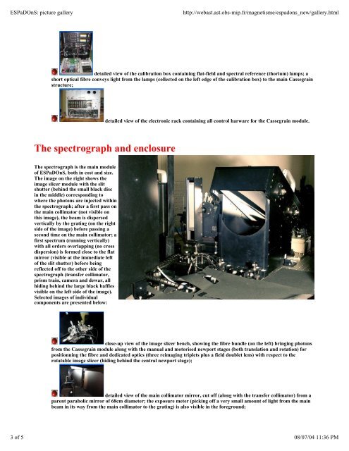
The spectrograph and enclosure<br />
The spectrograph is the main module<br />
of ESPaDOnS, both in cost and size.<br />
The image on the right shows the<br />
image slicer module with the slit<br />
shutter (behind the small black disc<br />
in the middle) corresponding to<br />
where the photons are injected within<br />
the spectrograph; after a first pass on<br />
the main collimator (not visible on<br />
this image), the beam is dispersed<br />
vertically by the grating (on the right<br />
side of the image) before passing a<br />
second time on the main collimator; a<br />
first spectrum (running vertically)<br />
with all orders overlapping (no cross<br />
dispersion) is formed close to the flat<br />
mirror (visible at the immediate left<br />
of the slit shutter) before being<br />
reflected off to the other side of the<br />
spectrograph (transfer collimator,<br />
prism train, camera and dewar, all<br />
hiding behind the large black baffles<br />
visible on the left side of the image).<br />
Selected images of individual<br />
components are presented below:<br />
detailed view of the electronic rack containing all control harware for the Cassegrain module.<br />
close-up view of the image slicer bench, showing the fibre bundle (on the left) bringing photons<br />
from the Cassegrain module along with the <strong>manual</strong> and motorised newport stages (both translation and rotation) for<br />
positionning the fibre and dedicated optics (three reimaging triplets plus a field doublet lens) with respect to the<br />
rotatable image slicer (hiding behind the central newport stage);<br />
detailed view of the main collimator mirror, cut off (along with the transfer collimator) from a<br />
parent parabolic mirror of 68cm diameter; the exposure meter (picking off a very small amount of light from the main<br />
beam in its way from the main collimator to the grating) is also visible in the foreground;<br />
3 of 5 08/07/04 11:36 PM