Regularization of the AVO inverse problem by means of a ...
Regularization of the AVO inverse problem by means of a ...
Regularization of the AVO inverse problem by means of a ...

Create successful ePaper yourself
Turn your PDF publications into a flip-book with our unique Google optimized e-Paper software.
CHAPTER 2. <strong>AVO</strong> MODELING 22<br />
!<br />
$%!<br />
$!<br />
!#!<br />
!&!<br />
!"#<br />
$&! $#! '#! '&! '%!<br />
(#! (&!<br />
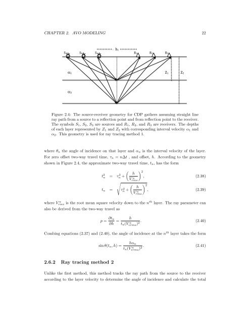
Figure 2.4: The source-receiver geometry for CDP ga<strong>the</strong>rs assuming straight line<br />
ray path from a source to a reflection point and from reflection point to <strong>the</strong> receiver.<br />
The symbols S1, S2, S3 are sources and R1, R2, and R3 are receivers. The depths<br />
<strong>of</strong> each layer represented <strong>by</strong> Z1 and Z2 with corresponding interval velocity α1 and<br />
α2. This geometry is used for ray tracing method 1.<br />
where θn <strong>the</strong> angle <strong>of</strong> incidence on that layer and αn is <strong>the</strong> interval velocity <strong>of</strong> <strong>the</strong> layer.<br />
For zero <strong>of</strong>fset two-way travel time, τn = n∆t , and <strong>of</strong>fset, h. According to <strong>the</strong> geometry<br />
shown in Figure 2.4, <strong>the</strong> approximate two-way travel time, tn, has <strong>the</strong> form<br />
t 2 n = τ 2 <br />
h<br />
n +<br />
tn =<br />
<br />
τ 2 n +<br />
V n<br />
rms<br />
h<br />
V n<br />
rms<br />
2<br />
, (2.38)<br />
2<br />
, (2.39)<br />
where V n<br />
rms is <strong>the</strong> root mean square velocity down to <strong>the</strong> n th layer. The ray parameter can<br />
also be derived from <strong>the</strong> two-way travel as<br />
p = ∂tn<br />
∂h =<br />
h<br />
tn(V n . (2.40)<br />
2<br />
vrms)<br />
Combing equations (2.37) and (2.40), <strong>the</strong> angle <strong>of</strong> incidence at <strong>the</strong> n th layer takes <strong>the</strong> form<br />
sin θ(tn, h) =<br />
2.6.2 Ray tracing method 2<br />
hαn<br />
tn(V n . (2.41)<br />
2<br />
vrms)<br />
Unlike <strong>the</strong> first method, this method tracks <strong>the</strong> ray path from <strong>the</strong> source to <strong>the</strong> receiver<br />
according to <strong>the</strong> layer velocity to determine <strong>the</strong> angle <strong>of</strong> incidence and calculate <strong>the</strong> total