ASD2620HE Amana Refrigerator Service Manual - Appliance 911 ...
ASD2620HE Amana Refrigerator Service Manual - Appliance 911 ...
ASD2620HE Amana Refrigerator Service Manual - Appliance 911 ...

Create successful ePaper yourself
Turn your PDF publications into a flip-book with our unique Google optimized e-Paper software.
<strong>Service</strong> Procedures<br />
Evacuation and Charging<br />
!<br />
CAUTION<br />
To avoid risk of fire, sealed refrigeration system<br />
must be air free. To avoid risk of air contamination,<br />
follow evacuation procedures exactly.<br />
NOTE: Before opening any refrigeration system, EPA<br />
regulations require refrigerant in system to be<br />
captured for safe disposal.<br />
Proper evacuation of sealed refrigeration system is an<br />
important service procedure. Usable life and<br />
operational efficiency greatly depends upon how<br />
completely air, moisture and other non-condensables<br />
are evacuated from sealed system.<br />
Air in sealed system causes high condensing<br />
temperature and pressure, resulting in increased<br />
power requirements and reduced performance.<br />
Moisture in sealed system chemically reacts with<br />
refrigerant and oil to form corrosive hydrofluoric and<br />
hydrochloric acids. These acids attack motor windings<br />
and parts, causing premature breakdown.<br />
Before opening system, evaporator coil must be at<br />
ambient temperature to minimize moisture infiltration<br />
into system.<br />
Evacuation<br />
To evacuate sealed refrigeration system:<br />
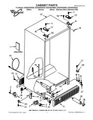
1. Connect vacuum pump, vacuum tight manifold set<br />
with high vacuum hoses, thermocouple vacuum<br />
gauge and charging cylinder as shown in illustration.<br />
Evacuation should be done through I.D. opening of<br />
tubes not through line piercing valve.<br />
2. Connect low side line to compressor process tube.<br />
3. Connect high side line to drier/process tube.<br />
4. Evacuate both simultaneously. With valve “C” and “F”<br />
closed, open all other valves and start vacuum pump.<br />
! WARNING<br />
To avoid risk of electrical shock, personal injury, or death, disconnect electrical power source to unit, unless test<br />
procedures require power to be connected. Discharge capacitor through a 10,000 ohm resistor before attempting<br />
to service. Ensure all ground wires are connected before certifying unit as repaired and/or operational.<br />
Thermistor<br />
Vacuum Gauge<br />
Compressor<br />
Compressor<br />
Process<br />
Tube<br />
.6 cm Copper<br />
Tubing<br />
Low Side Gauge<br />
Charging Hose<br />
Vacuum Pump<br />
©2005 Maytag <strong>Service</strong>s 16025628 15<br />
E<br />
Valve<br />
High Side Gauge<br />
D<br />
Valve<br />
C<br />
B<br />
A<br />
Drier/Process Tube<br />
Charging Hose<br />
Charging<br />
Cylinder<br />
F<br />
Valve<br />
Equipment Setup For Evacuation And Charging<br />
5. After compound gauge (low side) drops to<br />
approximately 29 inches gauge, open valve “C” to<br />
vacuum thermocouple gauge and take micron<br />
reading.<br />
NOTE: A high vacuum pump can only produce a good<br />
vacuum if oil in pump is not contaminated.<br />
6. Continue evacuating system until vacuum gauge<br />
registers 600 microns.<br />
7. At 600 microns, close valve “A” to vacuum pump and<br />
allow micron reading in system to balance. Micron<br />
level will rise.<br />
If in 2 minutes, micron level stabilizes at 1000<br />
microns or below, system is ready to be charged.<br />
If micron level rises above 1000 microns and<br />
stabilizes, open valve “A” and continue evacuating.<br />
If micron reading rises rapidly and does not<br />
stabilize, a leak still exists in system.<br />
Close valve “A” to vacuum pump and valve “C” to<br />
vacuum gauge. Invert charging cylinder and open<br />
charging cylinder valve “F” to add partial charge for<br />
leak checking. With leak detector, check manifold<br />
connections and system for leaks. After locating<br />
leak, capture refrigerant, repair leak, and begin at<br />
step 1.