

819-0001 JUN 07.pdf - Frymaster
819-0001 JUN 07.pdf - Frymaster
819-0001 JUN 07.pdf - Frymaster

Create successful ePaper yourself
Turn your PDF publications into a flip-book with our unique Google optimized e-Paper software.
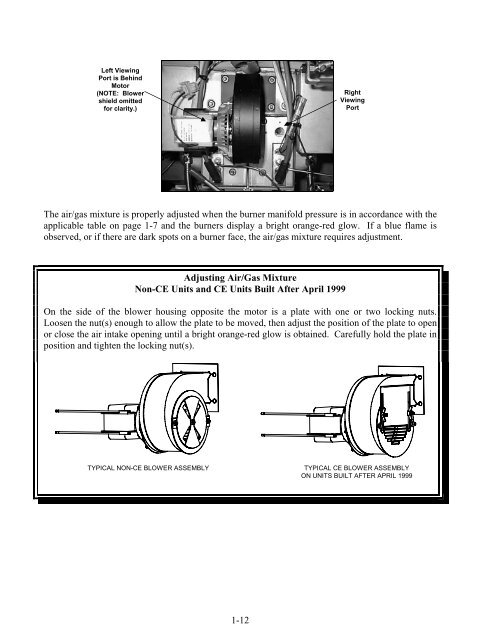
Left Viewing<br />
Port is Behind<br />
Motor<br />
(NOTE: Blower<br />
shield omitted<br />
for clarity.)<br />
The air/gas mixture is properly adjusted when the burner manifold pressure is in accordance with the<br />
applicable table on page 1-7 and the burners display a bright orange-red glow. If a blue flame is<br />
observed, or if there are dark spots on a burner face, the air/gas mixture requires adjustment.<br />
Adjusting Air/Gas Mixture<br />
Non-CE Units and CE Units Built After April 1999<br />
On the side of the blower housing opposite the motor is a plate with one or two locking nuts.<br />
Loosen the nut(s) enough to allow the plate to be moved, then adjust the position of the plate to open<br />
or close the air intake opening until a bright orange-red glow is obtained. Carefully hold the plate in<br />
position and tighten the locking nut(s).<br />
TYPICAL NON-CE BLOWER ASSEMBLY TYPICAL CE BLOWER ASSEMBLY<br />
ON UNITS BUILT AFTER APRIL 1999<br />
1-12<br />
Right<br />
Viewing<br />
Port


