

819-0001 JUN 07.pdf - Frymaster
819-0001 JUN 07.pdf - Frymaster
819-0001 JUN 07.pdf - Frymaster

You also want an ePaper? Increase the reach of your titles
YUMPU automatically turns print PDFs into web optimized ePapers that Google loves.
the other leg of the heat relay coils, which then close electronic switches in the 24 VAC circuit to<br />
provide current to the ignition module. Circuitry in the ignition module sends 24 VAC to the gas<br />
valve via a normally closed high-limit switch (and, in fryers with built-in filtration systems, a<br />
normally closed drain safety switch). Simultaneously, the module causes the ignitor to spark for 4<br />
seconds to light the burner. A flame sensor verifies the burner ignition by measuring the flow of<br />
microamps through the flame. If the burner does not light (or is extinguished), current to the<br />
ignition module is cut, the gas valve closes, and the ignition module “locks out” until the power<br />
switch is turned off and then back on. A probe monitors the temperature in the frypot. When the<br />
programmed setpoint temperature is reached, resistance in the probe causes the heat cycle circuitry<br />
in the controller to cut off current flow through the heat relay. This in turn cuts off the 24 VAC to<br />
the ignition module, causing the gas valve to close.<br />
INTERFACE BOARDS<br />
All fryers in this series have an interface board located in the component box located behind the<br />
control panel. The interface board provides a link between the controller/computer and the fryer’s<br />
individual components without requiring excessive wiring, and allows the controller to execute<br />
commands from one central point. The H50 Series of fryers has been in production since 1983.<br />
Consequently, servicers are likely to encounter three different interface board designs. Although the<br />
boards differ slightly in appearance, basic functioning and electrical connections are the same from<br />
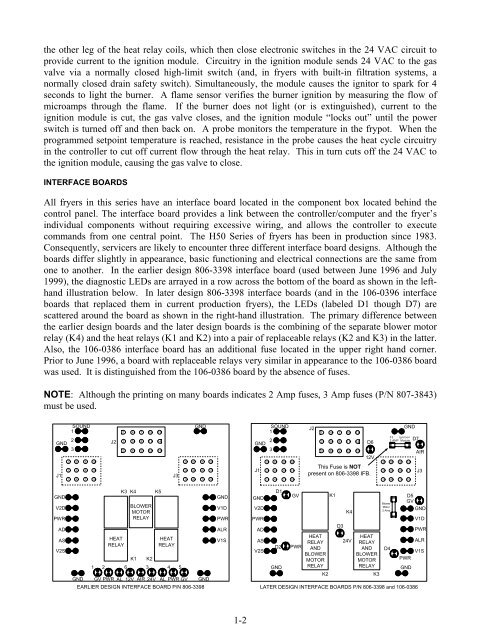
one to another. In the earlier design 806-3398 interface board (used between June 1996 and July<br />
1999), the diagnostic LEDs are arrayed in a row across the bottom of the board as shown in the lefthand<br />
illustration below. In later design 806-3398 interface boards (and in the 106-0396 interface<br />
boards that replaced them in current production fryers), the LEDs (labeled D1 though D7) are<br />
scattered around the board as shown in the right-hand illustration. The primary difference between<br />
the earlier design boards and the later design boards is the combining of the separate blower motor<br />
relay (K4) and the heat relays (K1 and K2) into a pair of replaceable relays (K2 and K3) in the latter.<br />
Also, the 106-0386 interface board has an additional fuse located in the upper right hand corner.<br />
Prior to June 1996, a board with replaceable relays very similar in appearance to the 106-0386 board<br />
was used. It is distinguished from the 106-0386 board by the absence of fuses.<br />
NOTE: Although the printing on many boards indicates 2 Amp fuses, 3 Amp fuses (P/N 807-3843)<br />
must be used.<br />
GND<br />
J1<br />
GND<br />
V2D<br />
PWR<br />
AD<br />
AS<br />
V2S<br />
SOUND<br />
1<br />
2<br />
3<br />
3 6 9 12<br />
2 5 8 11<br />
1 4 7 10<br />
J2<br />
1<br />
2<br />
3<br />
HEAT<br />
RELAY<br />
4<br />
5<br />
6<br />
K3 K4 K5<br />
K1 K2<br />
1 2 6 3 4 5<br />
7<br />
8<br />
9<br />
GND<br />
GND GV PWR AL 12V AIR 24V AL PWR GV GND<br />
EARLIER DESIGN INTERFACE BOARD P/N 806-3398<br />
10<br />
11<br />
12<br />
BLOWER<br />
MOTOR<br />
RELAY<br />
13<br />
14<br />
15<br />
J3<br />
HEAT<br />
RELAY<br />
3 6 9 12<br />
2 5 8 11<br />
1 4 7 10<br />
GND<br />
V1D<br />
PWR<br />
ALR<br />
V1S<br />
1-2<br />
GND<br />
J1<br />
GND<br />
V2D<br />
PWR<br />
AD<br />
AS<br />
V2S<br />
SOUND<br />
1<br />
2<br />
3<br />
3 6 9 12<br />
2 5 8 11<br />
1 4 7 10<br />
D1<br />
D2<br />
GND<br />
GV<br />
PWR<br />
J2<br />
1<br />
2<br />
3<br />
12V<br />
This Fuse is NOT<br />
present on 806-3398 IFB.<br />
HEAT<br />
RELAY<br />
AND<br />
BLOWER<br />
MOTOR<br />
RELAY<br />
4<br />
5<br />
6<br />
K1<br />
7<br />
8<br />
9<br />
D3<br />
K4<br />
24V<br />
GND<br />
3 6 9 12<br />
2 5 8 11<br />
1 4 7 10<br />
AIR<br />
D5<br />
GV<br />
GND<br />
V1D<br />
PWR<br />
ALR<br />
V1S<br />
PWR<br />
GND<br />
LATER DESIGN INTERFACE BOARDS P/N 806-3398 and 106-0386<br />
10<br />
11<br />
12<br />
13<br />
14<br />
15<br />
D6<br />
HEAT<br />
RELAY<br />
AND<br />
BLOWER<br />
MOTOR<br />
RELAY<br />
K2 K3<br />
Blower<br />
Motor<br />
2 Amp<br />
D4<br />
F2 Ignition<br />
2 AMP Module<br />
D7<br />
J3


