You also want an ePaper? Increase the reach of your titles
YUMPU automatically turns print PDFs into web optimized ePapers that Google loves.
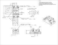
From the same brass stock, make the “U”<br />
shaped support bracket (the top of the<br />
bracket to be level with the top of the<br />
needle beam) and secure to the centre<br />
beam with brass pins. Make the 4mm x<br />
0.5mm brake lever, about 35mm long, drill<br />
three holes, as shown and connect to the<br />
“U” bracket. Set the two brake levers at<br />
about 25 degrees off square and install the<br />
main connecting rod. This rod can be<br />
made from 1.65mm copper or brass rod,<br />
hammered flat at each end. Drill a<br />
connecting pinhole at each end and<br />
connect with brass pins. Clevises can be<br />
used on each end of the main rod instead of flatting out the ends. I just happen to have run out of<br />
clevises<br />
at the time.<br />
From the clevis hole, near the piston clevis<br />
on<br />
the main brake lever, run a length of<br />
0.8mm brass wire to the brake wheel<br />
bracket. About an inch from the bracket,<br />
cut the wire and form a loop for the brake<br />
chain. Install a short length of suitable<br />
brass brake chain. This chain will latter be<br />
fixed to<br />
the brake wheel staff, between the<br />
brake<br />
bracket and end beam.