

Implementing IIR/FIR Filters
Implementing IIR/FIR Filters
Implementing IIR/FIR Filters

Create successful ePaper yourself
Turn your PDF publications into a flip-book with our unique Google optimized e-Paper software.
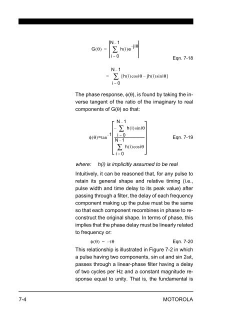
G( θ)<br />
hi ()e jiθ –<br />
N– 1<br />
=<br />
i = 0<br />
Eqn. 7-18<br />
The phase response, φ(θ), is found by taking the inverse<br />
tangent of the ratio of the imaginary to real<br />
components of G(θ) so that:<br />
φθ ( )=tan 1 –<br />
where: h(i) is implicitly assumed to be real<br />
Eqn. 7-19<br />
Intuitively, it can be reasoned that, for any pulse to<br />
retain its general shape and relative timing (i.e.,<br />
pulse width and time delay to its peak value) after<br />
passing through a filter, the delay of each frequency<br />
component making up the pulse must be the same<br />
so that each component recombines in phase to reconstruct<br />
the original shape. In terms of phase, this<br />
implies that the phase delay must be linearly related<br />
to frequency or:<br />
φθ ( ) =<br />
– τθ<br />
Eqn. 7-20<br />
This relationship is illustrated in Figure 7-2 in which<br />
a pulse having two components, sin ωt and sin 2ωt,<br />
passes through a linear-phase filter having a delay<br />
of two cycles per Hz and a constant magnitude response<br />
equal to unity. That is, the fundamental is<br />
7-4 MOTOROLA<br />
∑<br />
N– 1<br />
= ∑ [ hi () cosiθ–<br />
jh() i siniθ]<br />
i = 0<br />
N– 1<br />
– ∑ hi () siniθ<br />
i =<br />
--------------------------------------<br />
0<br />
N– 1<br />
∑<br />
hi () cosiθ<br />
i = 0


