

Implementing IIR/FIR Filters
Implementing IIR/FIR Filters
Implementing IIR/FIR Filters

You also want an ePaper? Increase the reach of your titles
YUMPU automatically turns print PDFs into web optimized ePapers that Google loves.
φΩ ( ) tan 1 –<br />
d<br />
k<br />
Ω/Ω<br />
c<br />
( Ω/Ω<br />
c<br />
) 2 N/2<br />
= ∑ -----------------------------k<br />
= 1<br />
– 1<br />
Eqn. 5-12<br />
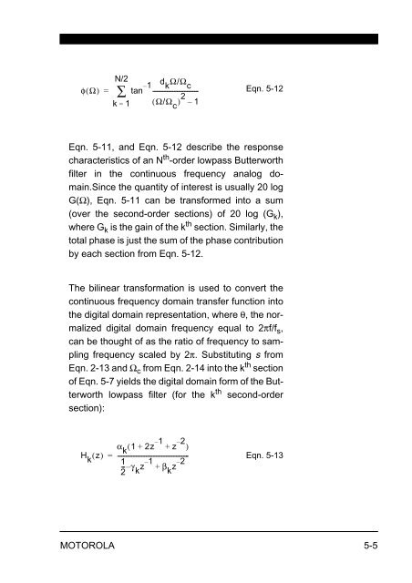
Eqn. 5-11, and Eqn. 5-12 describe the response<br />
characteristics of an N th -order lowpass Butterworth<br />
filter in the continuous frequency analog domain.Since<br />
the quantity of interest is usually 20 log<br />
G(Ω), Eqn. 5-11 can be transformed into a sum<br />
(over the second-order sections) of 20 log (G k ),<br />
where G k is the gain of the k th section. Similarly, the<br />
total phase is just the sum of the phase contribution<br />
by each section from Eqn. 5-12.<br />
The bilinear transformation is used to convert the<br />
continuous frequency domain transfer function into<br />
the digital domain representation, where θ, the normalized<br />
digital domain frequency equal to 2πf/f s ,<br />
can be thought of as the ratio of frequency to sampling<br />
frequency scaled by 2π. Substituting s from<br />
Eqn. 2-13 and Ω c from Eqn. 2-14 into the k th section<br />
of Eqn. 5-7 yields the digital domain form of the Butterworth<br />
lowpass filter (for the k th second-order<br />
section):<br />
H<br />
k<br />
( z)<br />
α<br />
k<br />
1 2z 1 –<br />
z 2 –<br />
( + + )<br />
1<br />
-- γ<br />
2 k<br />
z 1 –<br />
β<br />
k<br />
z 2 –<br />
=<br />
-------------------------------------------------<br />
– +<br />
Eqn. 5-13<br />
MOTOROLA 5-5


