Implementing IIR/FIR Filters
Implementing IIR/FIR Filters
Implementing IIR/FIR Filters
You also want an ePaper? Increase the reach of your titles
YUMPU automatically turns print PDFs into web optimized ePapers that Google loves.
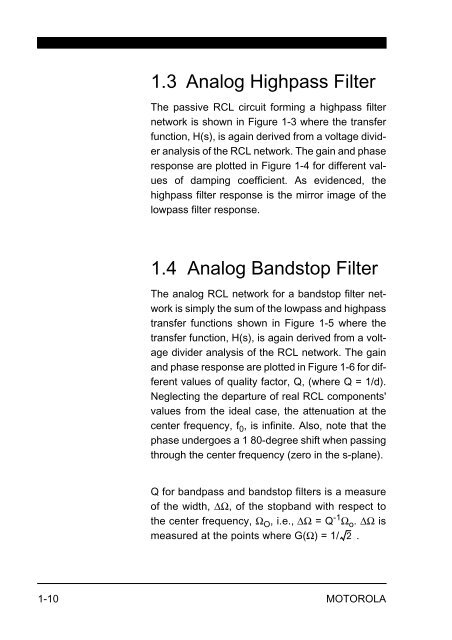
1.3 Analog Highpass Filter<br />
The passive RCL circuit forming a highpass filter<br />
network is shown in Figure 1-3 where the transfer<br />
function, H(s), is again derived from a voltage divider<br />
analysis of the RCL network. The gain and phase<br />
response are plotted in Figure 1-4 for different values<br />
of damping coefficient. As evidenced, the<br />
highpass filter response is the mirror image of the<br />
lowpass filter response.<br />
1.4 Analog Bandstop Filter<br />
The analog RCL network for a bandstop filter network<br />
is simply the sum of the lowpass and highpass<br />
transfer functions shown in Figure 1-5 where the<br />
transfer function, H(s), is again derived from a voltage<br />
divider analysis of the RCL network. The gain<br />
and phase response are plotted in Figure 1-6 for different<br />
values of quality factor, Q, (where Q = 1/d).<br />
Neglecting the departure of real RCL components'<br />
values from the ideal case, the attenuation at the<br />
center frequency, f 0 , is infinite. Also, note that the<br />
phase undergoes a 1 80-degree shift when passing<br />
through the center frequency (zero in the s-plane).<br />
Q for bandpass and bandstop filters is a measure<br />
of the width, ΔΩ, of the stopband with respect to<br />
the center frequency, ΩO , i.e., ΔΩ = Q-1Ωo . ΔΩ is<br />
measured at the points where G(Ω) = 1/ 2<br />
.<br />
1-10 MOTOROLA


