

Implementing IIR/FIR Filters
Implementing IIR/FIR Filters
Implementing IIR/FIR Filters

Create successful ePaper yourself
Turn your PDF publications into a flip-book with our unique Google optimized e-Paper software.
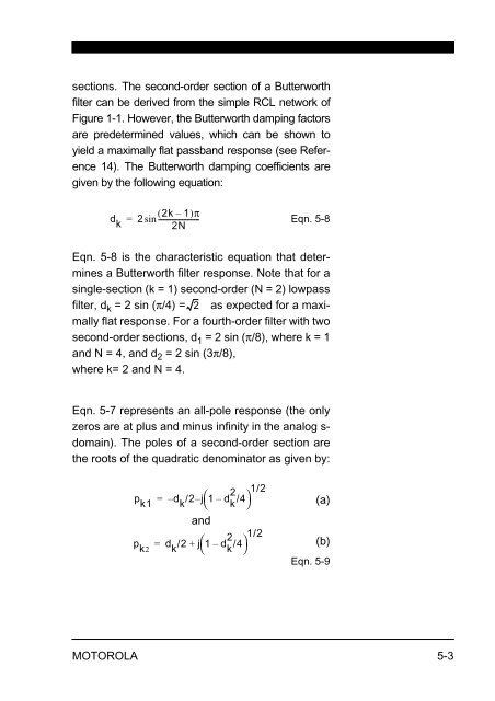
sections. The second-order section of a Butterworth<br />
filter can be derived from the simple RCL network of<br />
Figure 1-1. However, the Butterworth damping factors<br />
are predetermined values, which can be shown to<br />
yield a maximally flat passband response (see Reference<br />
14). The Butterworth damping coefficients are<br />
given by the following equation:<br />
d k<br />
( 2k – 1)π<br />
= 2sin----------------------<br />
2N<br />
Eqn. 5-8<br />
Eqn. 5-8 is the characteristic equation that determines<br />
a Butterworth filter response. Note that for a<br />
single-section (k = 1) second-order (N = 2) lowpass<br />
filter, dk = 2 sin (π/4) = 2 as expected for a maximally<br />
flat response. For a fourth-order filter with two<br />
second-order sections, d1 = 2 sin (π/8), where k = 1<br />
and N = 4, and d2 = 2 sin (3π/8),<br />
where k= 2 and N = 4.<br />
Eqn. 5-7 represents an all-pole response (the only<br />
zeros are at plus and minus infinity in the analog sdomain).<br />
The poles of a second-order section are<br />
the roots of the quadratic denominator as given by:<br />
p<br />
k1<br />
2 1/2<br />
= – d<br />
k<br />
/2–<br />
j1 ⎛ – d<br />
k<br />
/4⎞<br />
⎝ ⎠<br />
and<br />
p<br />
k2<br />
d<br />
k<br />
/2 j⎛ 2<br />
1 – d<br />
k<br />
/4⎞<br />
⎝ ⎠<br />
1/2<br />
=<br />
+<br />
MOTOROLA 5-3<br />
(a)<br />
(b)<br />
Eqn. 5-9


