

Implementing IIR/FIR Filters
Implementing IIR/FIR Filters
Implementing IIR/FIR Filters

You also want an ePaper? Increase the reach of your titles
YUMPU automatically turns print PDFs into web optimized ePapers that Google loves.
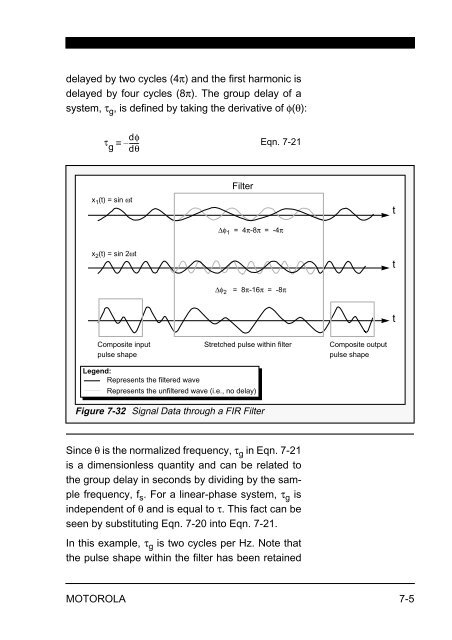
delayed by two cycles (4π) and the first harmonic is<br />
delayed by four cycles (8π). The group delay of a<br />
system, τ g , is defined by taking the derivative of φ(θ):<br />
dφ<br />
τ<br />
g<br />
≡ – -----dθ<br />
x 1 (t) = sin ωt<br />
x 2 (t) = sin 2ωt<br />
Composite input<br />
pulse shape<br />
Filter<br />
Figure 7-32 Signal Data through a <strong>FIR</strong> Filter<br />
Eqn. 7-21<br />
Δφ 1 = 4π-8π = -4π<br />
Δφ 2 = 8π-16π = -8π<br />
Legend:<br />
Represents the filtered wave<br />
Represents the unfiltered wave (i.e., no delay)<br />
Stretched pulse within filter Composite output<br />
pulse shape<br />
Since θ is the normalized frequency, τ g in Eqn. 7-21<br />
is a dimensionless quantity and can be related to<br />
the group delay in seconds by dividing by the sample<br />
frequency, f s . For a linear-phase system, τ g is<br />
independent of θ and is equal to τ. This fact can be<br />
seen by substituting Eqn. 7-20 into Eqn. 7-21.<br />
In this example, τ g is two cycles per Hz. Note that<br />
the pulse shape within the filter has been retained<br />
MOTOROLA 7-5<br />
t<br />
t<br />
t


