Implementing IIR/FIR Filters
Implementing IIR/FIR Filters
Implementing IIR/FIR Filters
You also want an ePaper? Increase the reach of your titles
YUMPU automatically turns print PDFs into web optimized ePapers that Google loves.
“In the directform<br />
implementation,<br />
the a i and b i are<br />
used directly in<br />
the difference<br />
equation, which<br />
can be easily<br />
programmed on<br />
a high-speed<br />
DSP such as the<br />
DSP56001.”<br />
SECTION 2<br />
Second-Order<br />
Direct-Form <strong>IIR</strong><br />
Digital Filter Sections<br />
The traditional approach to deriving the digital filter<br />
coefficients has been to start with the digital z-domain<br />
description, transform to the analog s-domain to understand<br />
how to design filters, then transform back to<br />
the digital domain to implement the filter. This approach<br />
is not used in this report. Instead, formulas are<br />
developed relating the s-domain filter to the z-domain<br />
filter so transformations to and from one domain to the<br />
other are no longer necessary.<br />
The Laplace or s-transform in the analog domain was<br />
developed to facilitate the analysis of continuous time<br />
signals and systems. For example, using Laplace<br />
transforms the concepts of poles and zeros, making<br />
system analysis much faster and more systematic.<br />
The Laplace transform of a continuous time signal is:<br />
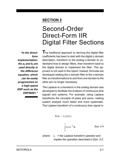
Xs ( ) = L{ x() t }<br />
xt ()e st –<br />
∞<br />
dt<br />
Eqn. 2-3<br />
where: L = the Laplace transform operator and<br />
implies the operation described in Eqn. 2-3<br />
MOTOROLA 2-1<br />
∫<br />
0


