

POWER-MASTER 500 - Victor Technologies
POWER-MASTER 500 - Victor Technologies
POWER-MASTER 500 - Victor Technologies

You also want an ePaper? Increase the reach of your titles
YUMPU automatically turns print PDFs into web optimized ePapers that Google loves.
3.01 Location<br />
SECTION 3:<br />
INSTALLATION<br />
Adequate air circulation is needed at all times in order to<br />
assure proper operation. Provide a minimum of 12 inches<br />
(305 mm) of free airspace on all sides of the unit. Make<br />
sure that the ventilator openings are not obstructed. Ventilation<br />
air flow is from rear to side.<br />
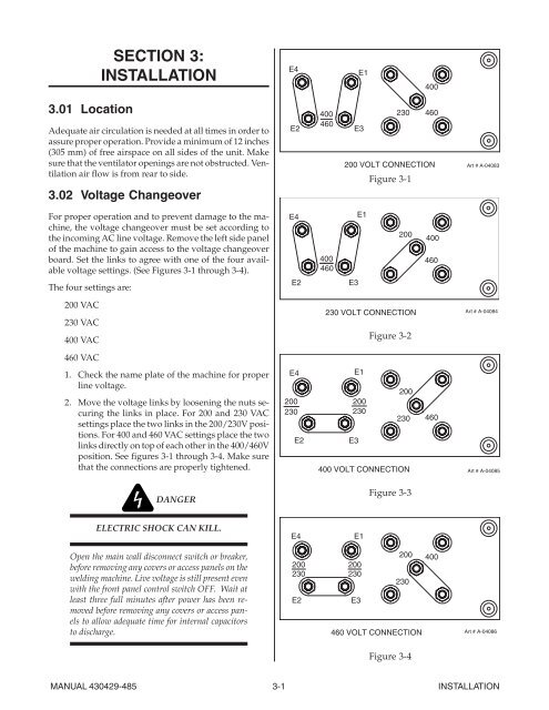
3.02 Voltage Changeover<br />
For proper operation and to prevent damage to the machine,<br />
the voltage changeover must be set according to<br />
the incoming AC line voltage. Remove the left side panel<br />
of the machine to gain access to the voltage changeover<br />
board. Set the links to agree with one of the four available<br />
voltage settings. (See Figures 3-1 through 3-4).<br />
The four settings are:<br />
200 VAC<br />
230 VAC<br />
400 VAC<br />
460 VAC<br />
1. Check the name plate of the machine for proper<br />
line voltage.<br />
2. Move the voltage links by loosening the nuts securing<br />
the links in place. For 200 and 230 VAC<br />
settings place the two links in the 200/230V positions.<br />
For 400 and 460 VAC settings place the two<br />
links directly on top of each other in the 400/460V<br />
position. See figures 3-1 through 3-4. Make sure<br />
that the connections are properly tightened.<br />
DANGER<br />
ELECTRIC SHOCK CAN KILL.<br />
Open the main wall disconnect switch or breaker,<br />
before removing any covers or access panels on the<br />
welding machine. Live voltage is still present even<br />
with the front panel control switch OFF. Wait at<br />
least three full minutes after power has been removed<br />
before removing any covers or access panels<br />
to allow adequate time for internal capacitors<br />
to discharge.<br />
MANUAL 430429-485 3-1 INSTALLATION<br />
E4<br />
E2<br />
E4<br />
400<br />
460<br />
400<br />
460<br />
E2 E3<br />
E4<br />
200<br />
230<br />
E2<br />
E1<br />
E3<br />
400<br />
230 460<br />
200 VOLT CONNECTION<br />
Figure 3-1<br />
E1<br />
200<br />
230 VOLT CONNECTION<br />
200<br />
230<br />
E3<br />
E1<br />
Figure 3-2<br />
400 VOLT CONNECTION<br />
E4 E1<br />
200<br />
230<br />
E2<br />
200<br />
230<br />
E3<br />
200<br />
230<br />
Figure 3-3<br />
230<br />
460 VOLT CONNECTION<br />
Figure 3-4<br />
400<br />
460<br />
460<br />
200 400<br />
Art # A-04083<br />
Art # A-04084<br />
Art # A-04085<br />
Art # A-04086


