

POWER-MASTER 500 - Victor Technologies
POWER-MASTER 500 - Victor Technologies
POWER-MASTER 500 - Victor Technologies

Create successful ePaper yourself
Turn your PDF publications into a flip-book with our unique Google optimized e-Paper software.
3.05 Grounding<br />
The frame of this welding machine should be grounded<br />
for personnel safety, and to assure operation of the<br />
overcurrent protection. The grounding method, and the<br />
equipment grounding conductor size and type shall conform<br />
to local and national codes.<br />
For the National Electrical Code, the equipment grounding<br />
conductor shall be green, green with a yellow stripe,<br />
or bare.<br />
If flexible power cable is used, use a cable assembly which<br />
includes the equipment grounding conductor. If metallic<br />
armored cable or conduit is used, the metal sheathing or<br />
conduit must be effectively grounded per local and national<br />
codes.<br />
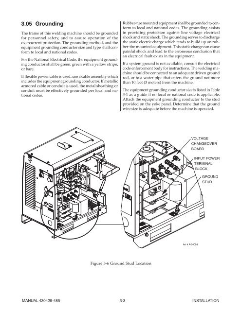
Figure 3-6 Ground Stud Location<br />
Rubber-tire mounted equipment shall be grounded to conform<br />
to local and national codes. The grounding assists<br />
in providing protection against line voltage electrical<br />
shock and static shock. The grounding serves to discharge<br />
the static electric charge which tends to build up on rubber-tire<br />
mounted equipment. This static charge can cause<br />
painful shock and lead to the erroneous conclusion that<br />
an electrical fault exists in the equipment.<br />
If a system ground is not available, consult the electrical<br />
code enforcement body for instructions. The welding machine<br />
should be connected to an adequate driven ground<br />
rod, or to a water pipe that enters the ground not more<br />
than 10 feet (3 meters) from the machine.<br />
The equipment grounding conductor size is listed in Table<br />
3-1 as a guide if no local or national code is applicable.<br />
Attach the equipment grounding conductor to the stud<br />
provided on the yoke panel. Determine that the ground<br />
wire size is adequate before the machine is operated.<br />
Art # A-04093<br />
VOLTAGE<br />
CHANGEOVER<br />
BOARD<br />
INPUT <strong>POWER</strong><br />
TERMINAL<br />
BLOCK<br />
GROUND<br />
STUD<br />
MANUAL 430429-485 3-3 INSTALLATION


