

POWER-MASTER 500 - Victor Technologies
POWER-MASTER 500 - Victor Technologies
POWER-MASTER 500 - Victor Technologies

Create successful ePaper yourself
Turn your PDF publications into a flip-book with our unique Google optimized e-Paper software.
3.03 Connecting Welding Machine<br />
to Line Voltage<br />
The input power should be connected to the unit through<br />
a fused disconnect switch, or other suitable disconnecting<br />
means furnished by the user. Access is provided in<br />
the rear panel of the machine for the entry of the input<br />
conductors.<br />
DANGER:<br />
ELECTRIC SHOCK CAN KILL.<br />
Open the disconnect switch, or breaker, and determine<br />
that no voltage is present, before connecting<br />
wires between welding machine and power supply.<br />
CAUTION:<br />
The method of installation, conductor size, and<br />
overcurrent protection shall conform to the requirements<br />
of the local electrical code, the National Electrical<br />
Code, or other national codes, as applicable.<br />
All installation wiring and machine reconnection<br />
shall be done by qualified persons.<br />
Table 3-1 provides minimal information for selection of<br />
line conductors, fuses, and the equipment grounding conductor.<br />
This information is from the National Electrical<br />
Code NFPA 70-1981 Edition. Install this equipment per<br />
the latest edition, available from the National Fire Protection<br />
Association, Batterymarch Park, Quincy, MA<br />
02269.<br />
Line<br />
Volts<br />
Rated Line<br />
Amps<br />
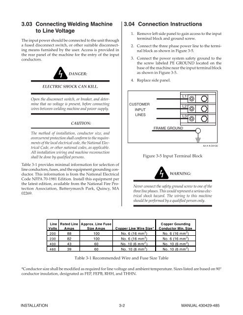
3.04 Connection Instructions<br />
1. Remove left side panel to gain access to the input<br />
terminal block and ground screw.<br />
2. Connect the three phase power line to the terminal<br />
block as shown in Figure 3-5.<br />
3. Connect the power system safety ground to the<br />
the screw labeled PE GROUND located on the<br />
base of the machine near the input terminal block<br />
as shown in Figure 3-5.<br />
4. Replace side panel.<br />
CUSTOMER<br />
INPUT<br />
LINES<br />
Approx. Line Fuse<br />
Size Amps Copper Line Wire Size*<br />
FRAME GROUND<br />
INSTALLATION 3-2 MANUAL 430429-485<br />
L1<br />
L2<br />
L3<br />
Figure 3-5 Input Terminal Block<br />
WARNING:<br />
Art # A-04100<br />
Never connect the safety ground screw to one of the<br />
three line phases. This would represent a serious electrical<br />
shock hazard. The wiring to this machine<br />
should be performed by a qualified person only.<br />
Copper Gounding<br />
Conductor Min. Size<br />
200 88 100 No. 6 (16 mm 2 ) No. 6 (16 mm 2 )<br />
230 82 100 No. 6 (16 mm 2 ) No. 6 (16 mm 2 )<br />
400 43 60 No. 10 (6 mm 2 ) No. 10 (6 mm 2 )<br />
460 39 60 No. 10 (6 mm 2 ) No. 10 (6 mm 2 )<br />
Table 3-1 Recommended Wire and Fuse Size Table<br />
*Conductor size shall be modified as required for line voltage and ambient temperature. Sizes listed are based on 90°<br />
conductor insulation, designated as FEP, FEPB, RHH, and THHN.


