visiferm™ do sensors - Forbes Marshall
visiferm™ do sensors - Forbes Marshall
visiferm™ do sensors - Forbes Marshall

You also want an ePaper? Increase the reach of your titles
YUMPU automatically turns print PDFs into web optimized ePapers that Google loves.
VISIFERM DO Operating Instructions<br />
Electrical connection for the ECS mode<br />
The ECS mode enables the simulation of an electrochemical sensor. Thus a<br />
VISIFERM DO sensor can be connected to classical measuring devices<br />
instead of amperometric oxygen <strong>sensors</strong> (Clark cells). Furthermore only the<br />
power supply of the VISIFERM DO sensor is necessary (VP 8.0 pins C and<br />
D, vide infra). Put the ECS mode into operation as described in the chapter<br />
‚Configuration of the sensor‘ / ‚Activation of the ECS mode‘!<br />
ATTENTION !<br />
Apply any high voltage (max. 2 VDC) at pin B (anode)! This can result<br />
in a destruction of the sensor in ECS mode! Note: Only in 4-20 mA<br />
mode a high voltage (max. 24 VDC) may be applied in order to operate<br />
the current interface!<br />
ATTENTION !<br />
Since the <strong>sensors</strong> are supplied in 4-20 mA mode by the factory the<br />
sensor initially has to be configured for the ECS mode (see chapter<br />
‘Configuration of the sensor‘)!<br />
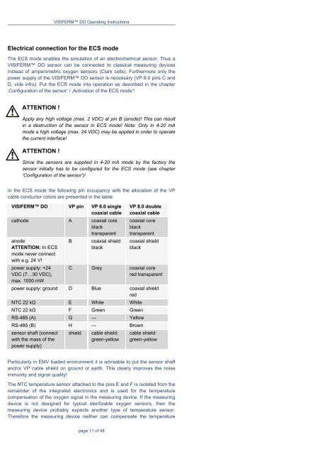
In the ECS mode the following pin occupancy with the allocation of the VP<br />
cable conductor colors are presented in the table:<br />
VISIFERM DO VP pin VP 6.0 single<br />
coaxial cable<br />
cathode A coaxial core<br />
black<br />
transparent<br />
anode<br />
ATTENTION: In ECS<br />
mode never connect<br />
with e.g. 24 V!<br />
power supply: +24<br />
VDC (7…30 VDC),<br />
max. 1000 mW<br />
B coaxial shield<br />
black<br />
page 11 of 48<br />
VP 8.0 <strong>do</strong>uble<br />
coaxial cable<br />
coaxial core<br />
black<br />
transparent<br />
coaxial shield<br />
black<br />
C Grey coaxial core<br />
red transparent<br />
power supply: ground D Blue coaxial shield<br />
red<br />
NTC 22 kΩ E White White<br />
NTC 22 kΩ F Green Green<br />
RS-485 (A) G --- Yellow<br />
RS-485 (B) H --- Brown<br />
sensor shaft (connect<br />
with the mass of the<br />
power supply)<br />
shield cable shield:<br />
green-yellow<br />
cable shield:<br />
green-yellow<br />
Particularly in EMV loaded environment it is advisable to put the sensor shaft<br />
and/or VP cable shield on ground or earth. This clearly improves the noise<br />
immunity and signal quality!<br />
The NTC temperature sensor attached to the pins E and F is isolated from the<br />
remainder of the integrated electronics and is used for the temperature<br />
compensation of the oxygen signal in the measuring device. If the measuring<br />
device is not designed for typical sterilizable oxygen <strong>sensors</strong>, then the<br />
measuring device probably expects another type of temperature sensor.<br />
Therefore the measuring device neither can compensate the temperature