
Create successful ePaper yourself
Turn your PDF publications into a flip-book with our unique Google optimized e-Paper software.
L1<br />
L2<br />
L3<br />
NPE<br />
F1<br />
5<br />
K1M<br />
6<br />
3 4<br />
1 2<br />
K0<br />
K2<br />
K1M<br />
1V3, 2V3 and U3<br />
only from size 0.75Hp<br />
EM and FEXT terminals<br />
are available on sizes<br />
3110 ... 5550 (230..480V)<br />
L1<br />
19<br />
18<br />
16<br />
15<br />
14<br />
13<br />
12<br />
39<br />
38<br />
37<br />
36<br />
85<br />
83<br />
82<br />
80<br />
1V3<br />
2V3<br />
U3<br />
EM<br />
EM<br />
FEXT<br />
FEXT<br />
PE1<br />
W1/L3<br />
V1/L2<br />
U1/L1<br />
+ 24V<br />
0 V24<br />
COM ID<br />
Fault<br />
External<br />
Fast stop<br />
Start<br />
Enable<br />
drive<br />
Dig. Inp.4<br />
Dig. Inp.3<br />
Dig. Inp.2<br />
Dig. Inp.1<br />
n>0<br />
( default )<br />
ok<br />
RS 485<br />
Keypad<br />
XE1<br />
Typischer Anschlussplan<br />
Diagrama Típico de Conexión<br />
46<br />
+30V<br />
41<br />
Dig. Out.2<br />
42<br />
Dig. Out.1<br />
Analog<br />
output 1<br />
Analog<br />
output 2<br />
Analog input 1<br />
Analog input 2<br />
Analog input 3<br />
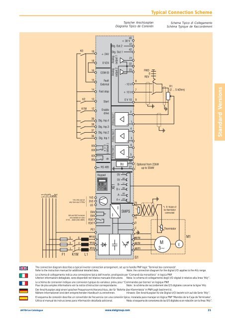
Typical Connection Scheme<br />
Schema Tipico di Collegamento<br />
Schéma Typique de Raccordement<br />
The connection diagram describes a typical inverter connection arrangement, set up to handle PNP logic "Terminal box commands".<br />
Refer to the instruction manual for additional detailed data. Note: the connection diagram for the digital I/O applies to the AVy range.<br />
Lo schema di collegamento indica una connessione tipica dell'inverter, predisposto per "Comandi da morsettiera" in logica PNP.<br />
Ulteriori informazioni dettagliate, sono disponibili nel relativo manuale d'istruzione. Nota: lo schema di collegamento degli I/O digitali è relativo alla linea “AVy”.<br />
Le schéma de connexion indique une connexion typique du variateur, prévu pour "Commandes par bornes" en logique PNP.<br />
Pour de plus amples informations voir la notice d'instruction correspondante. Note : le schéma de raccordement des E/S digitales concerne la ligne "AVy<br />
Der Anschlussplan zeigt einen typischen Frequenzumrichteranschluss, der für "Befehle über Klemmleiste" in PNP-Logik bestimmt ist.<br />
Nähere Informationen sind dem entsprechenden Handbuch zu entnehmen. Hinweis: Der Anschlussplan für die Digital-I/O bezieht sich auf die Serie “AVy”.<br />
El esquema de conexión describe un convertidor de frecuencia con una conexión típica, instalada para manejar en lógica PNP "Mandos de la Caja de Terminales".<br />
Utilice el manual de instrucciones para información detallada adicional. Nota: el esquema de conexiones de las E/S digitales es en relación con la línea “AVy”.<br />
<strong>ARTDrive</strong> <strong>Catalogue</strong> www.sieigroup.com 21<br />
0V<br />
5V<br />
B-<br />
B+<br />
A-<br />
BU<br />
8 1 9 7<br />
6<br />
A+ 5<br />
-10V<br />
+10V<br />
0V10<br />
SMPS<br />
+<br />
-<br />
- +<br />
- +<br />
21<br />
22<br />
23<br />
2<br />
1<br />
4<br />
3<br />
6<br />
5<br />
26<br />
27<br />
8<br />
7<br />
9<br />
79<br />
*)<br />
78<br />
D<br />
C<br />
W2/T3<br />
V2/T2<br />
U2/T1<br />
G1<br />
FWD<br />
0<br />
REV<br />
Optional from 22kW<br />
up to 55kW<br />
M<br />
3~<br />
R1<br />
(2 ... 5 kOhm)<br />
*) R 1Kohm if<br />
no thermistor<br />
connected<br />
Thermistor<br />
E<br />
M1<br />
Standard Versions