FortiGate-300A - Fortinet Technical Documentation
FortiGate-300A - Fortinet Technical Documentation
FortiGate-300A - Fortinet Technical Documentation

Create successful ePaper yourself
Turn your PDF publications into a flip-book with our unique Google optimized e-Paper software.
<strong>FortiGate</strong> <strong>300A</strong> Installation Guide<br />
Esc Enter<br />
CON SOLE USB<br />
10/100 10/100/ 1000<br />
1 2 3 4<br />
5<br />
6<br />
Version 2.80 MR5<br />
15 October 2004<br />
01-28005-0093-20041015
© Copyright 2004 <strong>Fortinet</strong> Inc. All rights reserved.<br />
No part of this publication including text, examples, diagrams or illustrations may be reproduced,<br />
transmitted, or translated in any form or by any means, electronic, mechanical, manual, optical or<br />
otherwise, for any purpose, without prior written permission of <strong>Fortinet</strong> Inc.<br />
<strong>FortiGate</strong>-<strong>300A</strong> Installation Guide<br />
Version 2.80 MR5<br />
15 October 2004<br />
01-28005-0093-20041015<br />
Trademarks<br />
Products mentioned in this document are trademarks or registered trademarks of their respective holders.<br />
Regulatory Compliance<br />
FCC Class A Part 15 CSA/CUS<br />
For technical support, please visit http://www.fortinet.com.<br />
Send information about errors or omissions in this document or any <strong>Fortinet</strong> technical documentation to<br />
techdoc@fortinet.com.
Table of Contents<br />
Introduction ............................................................................................................ 5<br />
Secure installation, configuration, and management.......................................................... 5<br />
Web-based manager ...................................................................................................... 6<br />
Command line interface .................................................................................................. 6<br />
Setup wizard ................................................................................................................... 7<br />
Document conventions ....................................................................................................... 7<br />
<strong>Fortinet</strong> documentation ....................................................................................................... 8<br />
Comments on <strong>Fortinet</strong> technical documentation............................................................. 8<br />
Customer service and technical support............................................................................. 9<br />
Getting started ..................................................................................................... 11<br />
Package contents ............................................................................................................. 12<br />
Mounting ........................................................................................................................... 12<br />
Turning the <strong>FortiGate</strong> unit power on and off ..................................................................... 13<br />
Connecting to the web-based manager............................................................................ 14<br />
Connecting to the command line interface (CLI)............................................................... 15<br />
Factory default <strong>FortiGate</strong> configuration settings ............................................................... 16<br />
Factory default NAT/Route mode network configuration .............................................. 17<br />
Factory default Transparent mode network configuration............................................. 18<br />
Factory default firewall configuration ............................................................................ 18<br />
Factory default protection profiles................................................................................. 19<br />
Planning the <strong>FortiGate</strong> configuration ................................................................................ 20<br />
NAT/Route mode .......................................................................................................... 20<br />
NAT/Route mode with multiple external network connections...................................... 21<br />
Transparent mode......................................................................................................... 22<br />
Configuration options .................................................................................................... 22<br />
Next steps......................................................................................................................... 23<br />
NAT/Route mode installation.............................................................................. 25<br />
Preparing to configure the <strong>FortiGate</strong> unit in NAT/Route mode ......................................... 25<br />
DHCP or PPPoE configuration ..................................................................................... 26<br />
Using the web-based manager......................................................................................... 27<br />
Configuring basic settings............................................................................................. 27<br />
Using the front control buttons and LCD........................................................................... 28<br />
Using the command line interface..................................................................................... 29<br />
Configuring the <strong>FortiGate</strong> unit to operate in NAT/Route mode ..................................... 29<br />
Using the setup wizard...................................................................................................... 32<br />
Starting the setup wizard .............................................................................................. 33<br />
Connecting the <strong>FortiGate</strong> unit to the network(s) ............................................................... 33<br />
Configuring the networks .................................................................................................. 34<br />
Next steps......................................................................................................................... 35<br />
Contents<br />
<strong>FortiGate</strong>-<strong>300A</strong> Installation Guide 01-28005-0093-20041015 3
Contents<br />
Transparent mode installation............................................................................ 37<br />
Preparing to configure Transparent mode ........................................................................ 37<br />
Using the web-based manager......................................................................................... 38<br />
Reconnecting to the web-based manager .................................................................... 39<br />
Using the front control buttons and LCD........................................................................... 39<br />
Using the command line interface..................................................................................... 40<br />
Using the setup wizard...................................................................................................... 42<br />
Reconnecting to the web-based manager .................................................................... 42<br />
Connecting the <strong>FortiGate</strong> unit to your network ................................................................. 42<br />
Next steps......................................................................................................................... 43<br />
High availability installation................................................................................ 45<br />
Priorities of heartbeat device and monitor priorities...................................................... 45<br />
Configuring <strong>FortiGate</strong> units for HA operation.................................................................... 45<br />
High availability configuration settings .......................................................................... 45<br />
Configuring <strong>FortiGate</strong> units for HA using the web-based manager .............................. 47<br />
Configuring <strong>FortiGate</strong> units for HA using the CLI.......................................................... 48<br />
Connecting the cluster to your networks........................................................................... 49<br />
Installing and configuring the cluster................................................................................. 51<br />
Index ...................................................................................................................... 53<br />
4 01-28005-0093-20041015 <strong>Fortinet</strong> Inc.
Introduction<br />
<strong>FortiGate</strong>-<strong>300A</strong> Installation Guide Version 2.80 MR5<br />
<strong>FortiGate</strong> Antivirus Firewalls improve network security, reduce network misuse and<br />
abuse, and help you use communications resources more efficiently without<br />
compromising the performance of your network. <strong>FortiGate</strong> Antivirus Firewalls are<br />
ICSA-certified for firewall, IPSec, and antivirus services.<br />
The <strong>FortiGate</strong> Antivirus Firewall is a dedicated easily managed security device that<br />
delivers a full suite of capabilities that include:<br />
• application-level services such as virus protection and content filtering,<br />
• network-level services such as firewall, intrusion detection, VPN, and traffic<br />
shaping.<br />
The <strong>FortiGate</strong> Antivirus Firewall uses <strong>Fortinet</strong>’s Accelerated Behavior and Content<br />
Analysis System (ABACAS) technology, which leverages breakthroughs in chip<br />
design, networking, security, and content analysis. The unique ASIC-based<br />
architecture analyzes content and behavior in real-time, enabling key applications to<br />
be deployed right at the network edge where they are most effective at protecting your<br />
networks.<br />
The <strong>FortiGate</strong>-<strong>300A</strong> model meets<br />
enterprise-class requirements for<br />
performance, availability, and reliability.<br />
The <strong>FortiGate</strong>-<strong>300A</strong> also supports<br />
advanced features such as 802.1Q VLAN<br />
support, virtual domains, high availability (HA), and the RIP and OSPF routing<br />
protocols. High-availability features include automatic failover with no session loss,<br />
making the <strong>FortiGate</strong>-<strong>300A</strong> the choice for mission critical applications.<br />
Secure installation, configuration, and management<br />
The <strong>FortiGate</strong> unit default configuration includes default interface IP addresses and is<br />
only a few steps away from protecting your network. There are several ways to<br />
configure basic <strong>FortiGate</strong> settings:<br />
• the web-based manager,<br />
• the front panel front keypad and LCD,<br />
• the command line interface (CLI), or<br />
• the setup wizard.<br />
The CLI or the web-based manager can then be used to complete configuration and<br />
to perform maintenance and administration.<br />
<strong>FortiGate</strong>-<strong>300A</strong> Installation Guide 01-28005-0093-20041015 5<br />
Esc Enter<br />
CONSOLE 10/100 10/100/1000<br />
USB<br />
1 2 3 4 5 6
Web-based manager Introduction<br />
Web-based manager<br />
Command line interface<br />
Using HTTP or a secure HTTPS connection from any computer running Internet<br />
Explorer, you can configure and manage the <strong>FortiGate</strong> unit. The web-based manager<br />
supports multiple languages. You can configure the <strong>FortiGate</strong> unit for HTTP and<br />
HTTPS administration from any <strong>FortiGate</strong> interface.<br />
You can use the web-based manager to configure most <strong>FortiGate</strong> settings. You can<br />
also use the web-based manager to monitor the status of the <strong>FortiGate</strong> unit.<br />
Configuration changes made using the web-based manager are effective immediately<br />
without resetting the firewall or interrupting service. Once you are satisfied with a<br />
configuration, you can download and save it. The saved configuration can be restored<br />
at any time.<br />
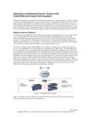
Figure 1: <strong>FortiGate</strong> web-based manager and setup wizard<br />
You can access the <strong>FortiGate</strong> command line interface (CLI) by connecting a<br />
management computer serial port to the <strong>FortiGate</strong> RS-232 serial console connector.<br />
You can also use Telnet or a secure SSH connection to connect to the CLI from any<br />
network that is connected to the <strong>FortiGate</strong> unit, including the Internet.<br />
The CLI supports the same configuration and monitoring functionality as the<br />
web-based manager. In addition, you can use the CLI for advanced configuration<br />
options that are not available from the web-based manager.<br />
This Installation Guide contains information about basic and advanced CLI<br />
commands. For a more complete description about connecting to and using the<br />
<strong>FortiGate</strong> CLI, see the <strong>FortiGate</strong> CLI Reference Guide.<br />
6 01-28005-0093-20041015 <strong>Fortinet</strong> Inc.
Introduction Setup wizard<br />
Setup wizard<br />
Document conventions<br />
The <strong>FortiGate</strong> setup wizard provides an easy way to configure the basic initial settings<br />
for the <strong>FortiGate</strong> unit. The wizard walks through the configuration of a new<br />
administrator password, <strong>FortiGate</strong> interfaces, DHCP server settings, internal servers<br />
(web, FTP, etc.), and basic antivirus settings.<br />
This guide uses the following conventions to describe command syntax.<br />
• Angle brackets < > to indicate variables.<br />
For example:<br />
execute restore config <br />
You enter:<br />
execute restore config myfile.bak<br />
indicates an ASCII string that does not contain new-lines or carriage<br />
returns.<br />
indicates an integer string that is a decimal (base 10) number.<br />
indicates a hexadecimal string that uses the digits 0-9 and letters<br />
A-F.<br />
indicates a dotted decimal IPv4 address.<br />
indicates a dotted decimal IPv4 netmask.<br />
indicates a dotted decimal IPv4 address followed by a dotted<br />
decimal IPv4 netmask.<br />
indicates a dotted decimal IPv6 address.<br />
indicates a dotted decimal IPv6 netmask.<br />
indicates a dotted decimal IPv6 address followed by a dotted<br />
decimal IPv6 netmask.<br />
• Vertical bar and curly brackets {|} to separate alternative, mutually exclusive<br />
required keywords.<br />
For example:<br />
set opmode {nat | transparent}<br />
You can enter set opmode nat or set opmode transparent.<br />
• Square brackets [ ] to indicate that a keyword or variable is optional.<br />
For example:<br />
show system interface []<br />
To show the settings for all interfaces, you can enter show system interface.<br />
To show the settings for the internal interface, you can enter show system<br />
interface internal.<br />
• A space to separate options that can be entered in any combination and must be<br />
separated by spaces.<br />
For example:<br />
<strong>FortiGate</strong>-<strong>300A</strong> Installation Guide 01-28005-0093-20041015 7
Comments on <strong>Fortinet</strong> technical documentation Introduction<br />
<strong>Fortinet</strong> documentation<br />
set allowaccess {ping https ssh snmp http telnet}<br />
You can enter any of the following:<br />
set allowaccess ping<br />
set allowaccess ping https ssh<br />
set allowaccess https ping ssh<br />
set allowaccess snmp<br />
In most cases to make changes to lists that contain options separated by spaces,<br />
you need to retype the whole list including all the options you want to apply and<br />
excluding all the options you want to remove.<br />
Information about <strong>FortiGate</strong> products is available from the following <strong>FortiGate</strong> Guides:<br />
• <strong>FortiGate</strong> QuickStart Guide<br />
Each QuickStart Guide provides the basic information required to connect and<br />
install a <strong>FortiGate</strong> model.<br />
• <strong>FortiGate</strong> Installation Guide<br />
Each Installation Guide provides detailed information required to install a <strong>FortiGate</strong><br />
model. Includes hardware reference, default configuration, installation procedures,<br />
connection procedures, and basic configuration procedures.<br />
• <strong>FortiGate</strong> Administration Guide<br />
Each Administration Guide describes how to configure a <strong>FortiGate</strong> model.<br />
Configuration information includes how to use <strong>FortiGate</strong> firewall policies to control<br />
traffic flow through the <strong>FortiGate</strong> unit and how to configure VPN, IPS, antivirus,<br />
web filtering, spam filtering. The administration guide also describes how to use<br />
protection profiles to apply intrusion prevention, antivirus protection, web content<br />
filtering, and spam filtering to traffic passing through the <strong>FortiGate</strong> unit.<br />
• <strong>FortiGate</strong> CLI Reference Guide<br />
Describes how to use the <strong>FortiGate</strong> CLI and contains a reference to all <strong>FortiGate</strong><br />
CLI commands.<br />
• <strong>FortiGate</strong> Log Message Reference Guide<br />
Describes the structure of <strong>FortiGate</strong> log messages and provides information on all<br />
log messages generated by the <strong>FortiGate</strong> unit.<br />
The <strong>FortiGate</strong> online help also contains procedures for using the <strong>FortiGate</strong> web-based<br />
manager to configure and manage the <strong>FortiGate</strong> unit. For a complete list of <strong>FortiGate</strong><br />
documentation visit <strong>Fortinet</strong> <strong>Technical</strong> Support at http://support.fortinet.com.<br />
Comments on <strong>Fortinet</strong> technical documentation<br />
You can send information about errors or omissions in this document, or any <strong>Fortinet</strong><br />
technical documentation, to techdoc@fortinet.com.<br />
8 01-28005-0093-20041015 <strong>Fortinet</strong> Inc.
Introduction Comments on <strong>Fortinet</strong> technical documentation<br />
Customer service and technical support<br />
For antivirus and attack definition updates, firmware updates, updated product<br />
documentation, technical support information, and other resources, please visit the<br />
<strong>Fortinet</strong> technical support web site at http://support.fortinet.com.<br />
You can also register <strong>FortiGate</strong> Antivirus Firewalls from http://support.fortinet.com and<br />
change your registration information at any time.<br />
<strong>Fortinet</strong> email support is available from the following addresses:<br />
amer_support@fortinet.com For customers in the United States, Canada, Mexico, Latin<br />
America and South America.<br />
apac_support@fortinet.com For customers in Japan, Korea, China, Hong Kong, Singapore,<br />
Malaysia, all other Asian countries, and Australia.<br />
eu_support@fortinet.com For customers in the United Kingdom, Scandinavia, Mainland<br />
Europe, Africa, and the Middle East.<br />
For information on <strong>Fortinet</strong> telephone support, see http://support.fortinet.com.<br />
When requesting technical support, please provide the following information:<br />
• Your name<br />
• Company name<br />
• Location<br />
• Email address<br />
• Telephone number<br />
• <strong>FortiGate</strong> unit serial number<br />
• <strong>FortiGate</strong> model<br />
• <strong>FortiGate</strong> FortiOS firmware version<br />
• Detailed description of the problem<br />
<strong>FortiGate</strong>-<strong>300A</strong> Installation Guide 01-28005-0093-20041015 9
Comments on <strong>Fortinet</strong> technical documentation Introduction<br />
10 01-28005-0093-20041015 <strong>Fortinet</strong> Inc.
Getting started<br />
<strong>FortiGate</strong>-<strong>300A</strong> Installation Guide Version 2.80 MR5<br />
This section describes unpacking, setting up, and powering on a <strong>FortiGate</strong> Antivirus<br />
Firewall unit. This section includes:<br />
• Package contents<br />
• Mounting<br />
• Turning the <strong>FortiGate</strong> unit power on and off<br />
• Connecting to the web-based manager<br />
• Connecting to the command line interface (CLI)<br />
• Factory default <strong>FortiGate</strong> configuration settings<br />
• Planning the <strong>FortiGate</strong> configuration<br />
• Next steps<br />
<strong>FortiGate</strong>-<strong>300A</strong> Installation Guide 01-28005-0093-20041015 11
Package contents<br />
Mounting<br />
The <strong>FortiGate</strong>-<strong>300A</strong> package contains the following items:<br />
• <strong>FortiGate</strong>-<strong>300A</strong> Antivirus Firewall<br />
• one orange crossover ethernet cable (<strong>Fortinet</strong> part number CC300248)<br />
• one gray regular ethernet cable (<strong>Fortinet</strong> part number CC300249)<br />
• one RJ-45 serial cable (<strong>Fortinet</strong> part number CC300302)<br />
• <strong>FortiGate</strong>-<strong>300A</strong> QuickStart Guide<br />
• one power cable<br />
• CD containing the <strong>FortiGate</strong> user documentation<br />
• two 19-inch rack mount brackets<br />
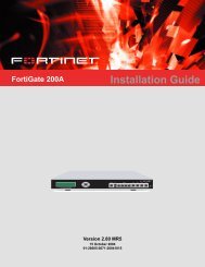
Figure 2: <strong>FortiGate</strong>-<strong>300A</strong> package contents<br />
LCD<br />
Getting started<br />
The <strong>FortiGate</strong>-<strong>300A</strong> unit can be installed on any stable surface.<br />
The <strong>FortiGate</strong>-<strong>300A</strong> unit can also be mounted on a standard 19-inch rack. It requires<br />
1 U of vertical space in the rack.<br />
Dimensions<br />
• 16.8 x 10 x 1.75 in. (42.7 x 25.4 x 4.5 cm)<br />
Weight<br />
• 7.3 lb. (3.3 kg)<br />
Esc Enter<br />
Front<br />
Control Serial<br />
Buttons Port<br />
Power USB<br />
LED (future)<br />
CONSOLE USB<br />
10/100 10/100/1000<br />
1 2 3 4 5 6<br />
Back<br />
1, 2, 3, 4<br />
10/100<br />
5, 6<br />
10/100/1000<br />
Power Power<br />
Connection Switch<br />
Ethernet Cables:<br />
Orange - Crossover<br />
Grey - Straight-through<br />
Power Cable<br />
Rack-Mount Brackets<br />
<strong>Documentation</strong><br />
12 01-28005-0093-20041015 <strong>Fortinet</strong> Inc.<br />
USER MANUAL<br />
RJ-45 Serial Cable<br />
<strong>FortiGate</strong>-<strong>300A</strong><br />
A<br />
Esc Enter<br />
Copyright 2003 <strong>Fortinet</strong> Incorporated. All rights reserved.<br />
Trademarks<br />
Products mentioned in this document are trademarks.<br />
CONSOLE USB<br />
INTERNAL DMZ1 DMZ2<br />
WAN1 WAN2<br />
1 2 3 4<br />
QuickStart Guide
Getting started<br />
Power requirements<br />
• Power dissipation: 50 W (max)<br />
• AC input voltage: 100 to 240 VAC<br />
• AC input current: 1.6 A<br />
• Frequency: 50 to 60 H<br />
Environmental specifications<br />
• Operating temperature: 32 to 104°F (0 to 40°C)<br />
• Storage temperature: -13 to 158°F (-25 to 70°C)<br />
• Humidity: 5 to 95% non-condensing<br />
If you install the <strong>FortiGate</strong>-<strong>300A</strong> unit in a closed or multi-unit rack assembly, the<br />
operating ambient temperature of the rack environment may be greater than room<br />
ambient. Make sure the operating ambient temperature does not exceed the<br />
manufacturer's maximum rated ambient temperature.<br />
Air flow<br />
• For rack installation, make sure that the amount of air flow required for safe<br />
operation of the <strong>FortiGate</strong> unit is not compromised.<br />
• For free-standing installation, make sure that the <strong>FortiGate</strong> unit has at least 1.5 in.<br />
(3.75 cm) of clearance on each side to allow for adequate air flow and cooling.<br />
Mechanical loading<br />
• For rack installation, make sure the mechanical loading of the <strong>FortiGate</strong> unit is<br />
evenly distributed to avoid a hazardous condition.<br />
Turning the <strong>FortiGate</strong> unit power on and off<br />
To power on the <strong>FortiGate</strong> unit<br />
1 Make sure that the power switch on the back of the <strong>FortiGate</strong> unit is turned off.<br />
2 Connect the power cable to the power connection on the back of the <strong>FortiGate</strong> unit.<br />
3 Connect the power cable to a power outlet.<br />
4 Turn on the power switch.<br />
After a few seconds, SYSTEM STARTING appears<br />
on the LCD.<br />
MAIN MENU appears on the LCD when the system<br />
is running.<br />
<strong>FortiGate</strong>-<strong>300A</strong> Installation Guide 01-28005-0093-20041015 13
Table 1: <strong>FortiGate</strong>-<strong>300A</strong> LED indicators<br />
Getting started<br />
LED State Description<br />
Power Green The <strong>FortiGate</strong> unit is powered on.<br />
Off The <strong>FortiGate</strong> unit is powered off.<br />
1, 2, 3, 4, 5, 6 Amber The correct cable is in use and the connected equipment has<br />
power.<br />
Flashing<br />
Amber<br />
Network activity at this interface.<br />
Green The interface is connected.<br />
• 1, 2, 3, and 4 connect at up to 100 Mbps.<br />
• 5 and 6 connect at up to 1000 Mbps.<br />
Off No link established.<br />
To power off the <strong>FortiGate</strong> unit<br />
Always shut down the <strong>FortiGate</strong> operating system properly before turning off the<br />
power switch.<br />
1 From the web-based manager, go to System > Maintenance > ShutDown, select<br />
Shut Down and select Apply, or from the CLI, enter:<br />
execute shutdown<br />
2 Turn off the power switch.<br />
3 Disconnect the power cable from the power supply.<br />
Connecting to the web-based manager<br />
Use the following procedure to connect to the web-based manager for the first time.<br />
Configuration changes made with the web-based manager are effective immediately<br />
without resetting the firewall or interrupting service.<br />
To connect to the web-based manager, you need:<br />
• a computer with an ethernet connection,<br />
• Internet Explorer version 6.0 or higher,<br />
• a crossover cable or an ethernet hub and two ethernet cables.<br />
Note: You can use the web-based manager with recent versions of most popular web browsers.<br />
The web-based manager is fully supported for Internet Explorer version 6.0 or higher.<br />
To connect to the web-based manager<br />
1 Set the IP address of the computer with an ethernet connection to the static IP<br />
address 192.168.1.2 with a netmask of 255.255.255.0.<br />
2 Using the crossover cable or the ethernet hub and cables, connect port 1 of the<br />
<strong>FortiGate</strong> unit to the computer ethernet connection.<br />
14 01-28005-0093-20041015 <strong>Fortinet</strong> Inc.
Getting started<br />
3 Start Internet Explorer and browse to the address https://192.168.1.99. (remember to<br />
include the “s” in https://).<br />
The <strong>FortiGate</strong> login is displayed.<br />
Figure 3: <strong>FortiGate</strong> login<br />
4 Type admin in the Name field and select Login.<br />
Connecting to the command line interface (CLI)<br />
As an alternative to the web-based manager, you can install and configure the<br />
<strong>FortiGate</strong> unit using the CLI. Configuration changes made with the CLI are effective<br />
immediately without resetting the firewall or interrupting service.<br />
To connect to the <strong>FortiGate</strong> CLI, you need:<br />
• a computer with an available communications port,<br />
• the RJ-45 serial cable included in your <strong>FortiGate</strong> package,<br />
• terminal emulation software such as HyperTerminal for Windows.<br />
Note: The following procedure describes how to connect to the CLI using Windows<br />
HyperTerminal software. You can use any terminal emulation program.<br />
To connect to the CLI<br />
1 Make sure that the <strong>FortiGate</strong> unit is powered on.<br />
2 Start HyperTerminal, enter a name for the connection, and select OK.<br />
3 Configure HyperTerminal to connect directly to the communications port on your<br />
computer and select OK.<br />
4 Select the following port settings and select OK.<br />
<strong>FortiGate</strong>-<strong>300A</strong> Installation Guide 01-28005-0093-20041015 15
Bits per second 9600<br />
Data bits 8<br />
Parity None<br />
Stop bits 1<br />
Flow control None<br />
Getting started<br />
5 Press Enter to connect to the <strong>FortiGate</strong> CLI.<br />
The following prompt is displayed:<br />
<strong>FortiGate</strong>-<strong>300A</strong> login:<br />
6 Type admin and press Enter twice.<br />
The following prompt is displayed:<br />
Welcome !<br />
Type ? to list available commands. For information about how to use the CLI, see the<br />
<strong>FortiGate</strong> CLI Reference Guide.<br />
Factory default <strong>FortiGate</strong> configuration settings<br />
The <strong>FortiGate</strong> unit is shipped with a factory default configuration. The default<br />
configuration allows you to connect to and use the <strong>FortiGate</strong> web-based manager to<br />
configure the <strong>FortiGate</strong> unit onto the network. To configure the <strong>FortiGate</strong> unit onto the<br />
network you add an administrator password, change network interface IP addresses,<br />
add DNS server IP addresses, and configure basic routing, if required.<br />
If you plan to operate the <strong>FortiGate</strong> unit in Transparent mode, you can switch to<br />
Transparent mode from the factory default configuration and then configure the<br />
<strong>FortiGate</strong> unit onto the network in Transparent mode.<br />
Once the network configuration is complete, you can perform additional configuration<br />
tasks such as setting system time, configuring virus and attack definition updates, and<br />
registering the <strong>FortiGate</strong> unit.<br />
The factory default protection profiles can be used to apply different levels of antivirus<br />
protection, web content filtering, spam filtering, and IPS to the network traffic that is<br />
controlled by firewall policies.<br />
• Factory default NAT/Route mode network configuration<br />
• Factory default Transparent mode network configuration<br />
• Factory default firewall configuration<br />
• Factory default protection profiles<br />
16 01-28005-0093-20041015 <strong>Fortinet</strong> Inc.
Getting started Factory default NAT/Route mode network configuration<br />
Factory default NAT/Route mode network configuration<br />
When the <strong>FortiGate</strong> unit is first powered on, it is running in NAT/Route mode and has<br />
the basic network configuration listed in Table 2. This configuration allows you to<br />
connect to the <strong>FortiGate</strong> unit web-based manager and establish the configuration<br />
required to connect the <strong>FortiGate</strong> unit to the network. In Table 2, HTTPS<br />
administrative access means you can connect to the web-based manager using<br />
HTTPS protocol through this interface. Ping administrative access means this<br />
interface responds to ping requests.<br />
Table 2: Factory default NAT/Route mode network configuration<br />
Administrator<br />
account<br />
Port 1<br />
Port 2<br />
Port 3<br />
Port 4<br />
Port 5<br />
Port 6<br />
Network Settings<br />
User name: admin<br />
Password: (none)<br />
IP: 192.168.1.99<br />
Netmask: 255.255.255.0<br />
Administrative Access: HTTPS, Ping<br />
IP: 192.168.100.99<br />
Netmask: 255.255.255.0<br />
Administrative Access: Ping<br />
IP: 0.0.0.0<br />
Netmask: 0.0.0.0<br />
Administrative Access: Ping<br />
IP: 10.10.10.1<br />
Netmask: 0.0.0.0<br />
Administrative Access: HTTPS, Ping<br />
IP: 0.0.0.0<br />
Netmask: 0.0.0.0<br />
Administrative Access: Ping<br />
IP: 0.0.0.0<br />
Netmask: 0.0.0.0<br />
Administrative Access: Ping<br />
Default Gateway (for default route) 192.168.100.1<br />
Interface connected to external network port2<br />
(for default route)<br />
Default Route<br />
A default route consists of a default gateway and the name of<br />
the interface connected to the external network (usually the<br />
Internet). The default gateway directs all non-local traffic to this<br />
interface and to the external network.<br />
Primary DNS Server 207.192.200.1<br />
Secondary DNS Server 207.192.200.129<br />
<strong>FortiGate</strong>-<strong>300A</strong> Installation Guide 01-28005-0093-20041015 17
Factory default Transparent mode network configuration Getting started<br />
Factory default Transparent mode network configuration<br />
In Transparent mode, the <strong>FortiGate</strong> unit has the default network configuration listed in<br />
Table 3.<br />
Table 3: Factory default Transparent mode network configuration<br />
Administrator<br />
account<br />
Management IP<br />
DNS<br />
Administrative access<br />
Factory default firewall configuration<br />
User name: admin<br />
Password: (none)<br />
IP: 10.10.10.1<br />
Netmask: 255.255.255.0<br />
Primary DNS Server: 207.194.200.1<br />
Secondary DNS Server: 207.194.200.129<br />
Port 1 HTTPS, Ping<br />
Port 2 Ping<br />
Port 3 Ping<br />
Port 4 HTTPS, Ping<br />
Port 5 Ping<br />
Port 6 Ping<br />
<strong>FortiGate</strong> firewall policies control how all traffic is processed by the <strong>FortiGate</strong> unit.<br />
Until firewall policies are added, no traffic can be accepted by or pass through the<br />
<strong>FortiGate</strong> unit. To allow traffic through the <strong>FortiGate</strong> unit you can add firewall policies.<br />
See the <strong>FortiGate</strong> Administration Guide for information about adding firewall policies.<br />
The following firewall configuration settings are included in the default firewall<br />
configuration to make it easier to add firewall policies.<br />
Table 4: Default firewall configuration<br />
Configuration setting Name Description<br />
Firewall address All Firewall address matches the source or<br />
destination address of any packet.<br />
Pre-defined service More than 50<br />
predefined services<br />
Select from any of the 50 pre-defined services<br />
to control traffic through the <strong>FortiGate</strong> unit that<br />
uses that service.<br />
Recurring schedule Always The recurring schedule is valid at any time.<br />
Protection Profiles Strict, Scan, Web,<br />
Unfiltered<br />
Control how the <strong>FortiGate</strong> unit applies virus<br />
scanning, web content filtering, spam filtering,<br />
and IPS.<br />
The factory default firewall configuration is the same in NAT/Route and Transparent<br />
mode.<br />
18 01-28005-0093-20041015 <strong>Fortinet</strong> Inc.
Getting started Factory default protection profiles<br />
Factory default protection profiles<br />
Use protection profiles to apply different protection settings for traffic that is controlled<br />
by firewall policies. You can use protection profiles to:<br />
• Configure antivirus protection for HTTP, FTP, IMAP, POP3, and SMTP firewall<br />
policies<br />
• Configure Web filtering for HTTP firewall policies<br />
• Configure Web category filtering for HTTP firewall policies<br />
• Configure spam filtering for IMAP, POP3, and SMTP firewall policies<br />
• Enable the Intrusion Protection System (IPS) for all services<br />
• Enable content logging for HTTP, FTP, IMAP, POP3, and SMTP firewall policies<br />
Using protection profiles, you can build protection configurations that can be applied<br />
to different types of firewall policies. This allows you to customize types and levels of<br />
protection for different firewall policies.<br />
For example, while traffic between internal and external addresses might need strict<br />
protection, traffic between trusted internal addresses might need moderate protection.<br />
You can configure firewall policies for different traffic services to use the same or<br />
different protection profiles.<br />
Protection profiles can be added to NAT/Route mode and Transparent mode firewall<br />
policies.<br />
The <strong>FortiGate</strong> unit comes preconfigured with four protection profiles.<br />
Strict To apply maximum protection to HTTP, FTP, IMAP, POP3, and SMTP traffic.<br />
You may not use the strict protection profile under normal circumstances but<br />
it is available if you have problems with viruses and require maximum<br />
screening.<br />
Scan To apply antivirus scanning to HTTP, FTP, IMAP, POP3, and SMTP content<br />
traffic. Quarantine is also selected for all content services. On <strong>FortiGate</strong><br />
models with a hard drive, if antivirus scanning finds a virus in a file, the file is<br />
quarantined on the <strong>FortiGate</strong> local disk. If required, system administrators<br />
can recover quarantined files.<br />
Web To apply antivirus scanning and web content blocking to HTTP content<br />
traffic. You can add this protection profile to firewall policies that control<br />
HTTP traffic.<br />
Unfiltered To apply no scanning, blocking or IPS. Use if you do not want to apply<br />
content protection to content traffic. You can add this protection profile to<br />
firewall policies for connections between highly trusted or highly secure<br />
networks where content does not need to be protected.<br />
<strong>FortiGate</strong>-<strong>300A</strong> Installation Guide 01-28005-0093-20041015 19
NAT/Route mode Getting started<br />
Figure 4: Web protection profile settings<br />
Planning the <strong>FortiGate</strong> configuration<br />
NAT/Route mode<br />
Before you configure the <strong>FortiGate</strong> unit, you need to plan how to integrate the unit into<br />
the network. Among other things, you must decide whether you want the unit to be<br />
visible to the network, which firewall functions you want it to provide, and how you<br />
want it to control the traffic flowing between its interfaces.<br />
Your configuration plan depends on the operating mode that you select. The <strong>FortiGate</strong><br />
unit can be configured in one of two modes: NAT/Route mode (the default) or<br />
Transparent mode.<br />
In NAT/Route mode, the <strong>FortiGate</strong> unit is visible to the network. Like a router, all its<br />
interfaces are on different subnets. The following interfaces are available in<br />
NAT/Route mode:<br />
• Ports 1, 2, 3, 4, 5, and 6 can be connected to any networks. By default, the<br />
<strong>FortiGate</strong>-<strong>300A</strong> interfaces have the following configuration<br />
• Port 1 is the default interface to the 10/100 Base-T internal network (usually the<br />
Internet).<br />
• Port 2 is the default interface to the 10/100 Base-T external network.<br />
• Port 3 can be connected to another 10/100 Base-T network such as a DMZ<br />
network.<br />
• Port 4 can be connected to another 10/100 Base-T network. Port 4 can also be<br />
connected to other <strong>FortiGate</strong>-300 units if you are installing an HA cluster.<br />
• Ports 5 and 6 can be connected to 10/100/1000 Base-T networks.<br />
You can add firewall policies to control whether communications through the <strong>FortiGate</strong><br />
unit operate in NAT or Route mode. Firewall policies control the flow of traffic based<br />
on the source address, destination address, and service of each packet. In NAT<br />
mode, the <strong>FortiGate</strong> unit performs network address translation before it sends the<br />
packet to the destination network. In Route mode, there is no address translation.<br />
20 01-28005-0093-20041015 <strong>Fortinet</strong> Inc.
Getting started NAT/Route mode with multiple external network connections<br />
You typically use NAT/Route mode when the <strong>FortiGate</strong> unit is operating as a gateway<br />
between private and public networks. In this configuration, you would create NAT<br />
mode firewall policies to control traffic flowing between the internal, private network<br />
and the external, public network (usually the Internet).<br />
If you have multiple internal networks, such as a DMZ network in addition to the<br />
internal, private network, you could create route mode firewall policies for traffic<br />
flowing between them.<br />
Figure 5: Example NAT/Route mode network configuration<br />
Internet Esc<br />
<strong>FortiGate</strong>-<strong>300A</strong> Unit<br />
in NAT/Route mode<br />
NAT/Route mode with multiple external network connections<br />
In NAT/Route mode, you can configure the <strong>FortiGate</strong> unit with multiple redundant<br />
connections to the external network (usually the Internet). For example, you could<br />
create the following configuration:<br />
• Port 1 is the interface to the internal network.<br />
• Port 2 is the default interface to the external network (usually the Internet).<br />
• Port 3 is the redundant interface to the external network.<br />
You must configure routing to support redundant Internet connections. Routing can be<br />
used to automatically redirect connections from an interface if its connection to the<br />
external network fails.<br />
Otherwise, security policy configuration is similar to a NAT/Route mode configuration<br />
with a single Internet connection. You would create NAT mode firewall policies to<br />
control traffic flowing between the internal, private network and the external, public<br />
network (usually the Internet).<br />
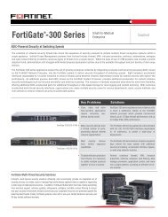
Figure 6: Example NAT/Route multiple internet connection configuration<br />
Internet<br />
Port 2<br />
204.23.1.5<br />
Port 3<br />
64.83.32.45<br />
Port 2<br />
204.23.1.5<br />
NAT mode policies controlling<br />
traffic between internal and<br />
external networks.<br />
Port 1<br />
192.168.1.99<br />
Port 4<br />
10.10.10.1<br />
Internal network<br />
192.168.1.3<br />
Route mode policies<br />
controlling traffic between<br />
internal networks.<br />
DMZ network<br />
10.10.10.2<br />
<strong>FortiGate</strong>-<strong>300A</strong> Installation Guide 01-28005-0093-20041015 21<br />
Enter<br />
<strong>FortiGate</strong>-<strong>300A</strong> Unit<br />
in NAT/Route mode<br />
Esc Enter<br />
CONSOLE 10/100 10/100/1000<br />
USB<br />
1 2 3 4 5 6<br />
NAT mode policies controlling<br />
traffic between internal and<br />
external networks.<br />
CONSOLE USB<br />
10/100 10/100/1000<br />
1 2 3 4 5 6<br />
Port 1<br />
192.168.1.1<br />
Internal network<br />
192.168.1.3
Transparent mode Getting started<br />
Transparent mode<br />
Configuration options<br />
In Transparent mode, the <strong>FortiGate</strong> unit is invisible to the network. Similar to a<br />
network bridge, all <strong>FortiGate</strong> interfaces must be on the same subnet. You only have to<br />
configure a management IP address so that you can make configuration changes.<br />
The management IP address is also used for antivirus and attack definition updates.<br />
You typically use the <strong>FortiGate</strong> unit in Transparent mode on a private network behind<br />
an existing firewall or behind a router. The <strong>FortiGate</strong> unit performs firewall functions,<br />
IPSec VPN, virus scanning, IPS, web content filtering, and Spam filtering.<br />
Figure 7: Example Transparent mode network configuration<br />
Gateway to<br />
public network<br />
204.23.1.5 10.10.10.2<br />
Internet<br />
(firewall, router)<br />
<strong>FortiGate</strong>-<strong>300A</strong> Unit<br />
in Transparent mode<br />
Port 2 Port 1<br />
Transparent mode policies<br />
controlling traffic between<br />
internal and external networks<br />
You can connect up to six network segments to the <strong>FortiGate</strong> unit to control traffic<br />
between these network segments.<br />
• Port 1 can connect to the internal firewall or router.<br />
• Port 2 can connect to the external network.<br />
• Ports 3, 4, 5, and 6 can connect to other networks.<br />
• Port 4 can also connect to other <strong>FortiGate</strong>-<strong>300A</strong> units if you are installing an HA<br />
cluster.<br />
Once you have selected Transparent or NAT/Route mode operation, you can<br />
complete the configuration plan and begin to configure the <strong>FortiGate</strong> unit. Choose<br />
among three different tools to configure the <strong>FortiGate</strong> unit<br />
Web-based manager and setup wizard<br />
10.10.10.1<br />
Management IP<br />
Internal network<br />
10.10.10.3<br />
The <strong>FortiGate</strong> web-based manager is a full featured management tool. You can use<br />
the web-based manager to configure most <strong>FortiGate</strong> settings.<br />
The web-based manager Setup Wizard guides you through the initial configuration<br />
steps. Use the Setup Wizard to configure the administrator password, the interface<br />
addresses, the default gateway address, and the DNS server addresses. Optionally,<br />
use the Setup Wizard to configure the internal server settings for NAT/Route mode.<br />
To connect to the web-based manager you require:<br />
• Ethernet connection between the <strong>FortiGate</strong> unit and a management computer.<br />
• Internet Explorer version 6.0 or higher on the management computer.<br />
22 01-28005-0093-20041015 <strong>Fortinet</strong> Inc.<br />
Esc Enter<br />
CONSOLE 10/100 10/100/1000<br />
USB<br />
1 2 3 4 5 6
Getting started Configuration options<br />
Next steps<br />
CLI<br />
The <strong>FortiGate</strong> CLI is a full-featured management tool. Use it to configure the<br />
administrator password, the interface addresses, the default gateway address, and<br />
the DNS server addresses. To connect to the CLI you require:<br />
• Serial connection between the <strong>FortiGate</strong> unit and a management computer.<br />
• A terminal emulation application on the management computer.<br />
Front control buttons and LCD<br />
If you are configuring the <strong>FortiGate</strong> unit to operate in NAT/Route mode, you can use<br />
the front keypad and LCD to add the IP address of the <strong>FortiGate</strong> interfaces as well as<br />
the external default gateway.<br />
If you are configuring the <strong>FortiGate</strong> unit to operate in Transparent mode, you can use<br />
the front keypad and LCD to switch to Transparent mode. Then you can add the<br />
management IP address and default gateway.<br />
If you are configuring the <strong>FortiGate</strong> unit to operate in Transparent mode, you can<br />
switch to Transparent mode from the web-based manager and then use the setup<br />
wizard to add the administration password, the management IP address and gateway,<br />
and the DNS server addresses.<br />
Now that your <strong>FortiGate</strong> unit is operating, you can proceed to configure it to connect to<br />
networks:<br />
• If you are going to operate the <strong>FortiGate</strong> unit in NAT/Route mode, go to<br />
“NAT/Route mode installation” on page 25.<br />
• If you are going to operate the <strong>FortiGate</strong> unit in Transparent mode, go to<br />
“Transparent mode installation” on page 37.<br />
• If you are going to operate two or more <strong>FortiGate</strong> units in HA mode, go to “High<br />
availability installation” on page 45.<br />
<strong>FortiGate</strong>-<strong>300A</strong> Installation Guide 01-28005-0093-20041015 23
Configuration options Getting started<br />
24 01-28005-0093-20041015 <strong>Fortinet</strong> Inc.
<strong>FortiGate</strong>-<strong>300A</strong> Installation Guide Version 2.80 MR5<br />
NAT/Route mode installation<br />
This chapter describes how to install the <strong>FortiGate</strong> unit in NAT/Route mode. For<br />
information about installing a <strong>FortiGate</strong> unit in Transparent mode, see “Transparent<br />
mode installation” on page 37. For information about installing two or more <strong>FortiGate</strong><br />
units in HA mode, see “High availability installation” on page 45. For more information<br />
about installing the <strong>FortiGate</strong> unit in NAT/Route mode, see “Planning the <strong>FortiGate</strong><br />
configuration” on page 20.<br />
This chapter describes:<br />
• Preparing to configure the <strong>FortiGate</strong> unit in NAT/Route mode<br />
• Using the web-based manager<br />
• Using the front control buttons and LCD<br />
• Using the command line interface<br />
• Using the setup wizard<br />
• Connecting the <strong>FortiGate</strong> unit to the network(s)<br />
• Configuring the networks<br />
• Next steps<br />
Preparing to configure the <strong>FortiGate</strong> unit in NAT/Route mode<br />
Use Table 5 to gather the information that you need to customize NAT/Route mode<br />
settings.<br />
You can configure the <strong>FortiGate</strong> unit in several ways:<br />
• the web-based manager GUI is a complete interface for configuring most settings.<br />
See “Using the web-based manager” on page 27.<br />
• the front control buttons and LCD provide access to basic settings “Using the front<br />
control buttons and LCD” on page 28.<br />
• the command line interface (CLI) is a complete text-based interface for configuring<br />
all settings. See “Using the command line interface” on page 29.<br />
• the setup wizard provides easy, fast configuration of the most basic settings to get<br />
the unit up and running quickly. See “Using the setup wizard” on page 32.<br />
The method that you choose depends on the complexity of the configuration, access<br />
and equipment, and the type of interface you are most comfortable using.<br />
<strong>FortiGate</strong>-<strong>300A</strong> Installation Guide 01-28005-0093-20041015 25
DHCP or PPPoE configuration NAT/Route mode installation<br />
Table 5: NAT/Route mode settings<br />
Administrator Password:<br />
Port 1<br />
Port 2<br />
Port 3<br />
Port 4<br />
Port 5<br />
Port 6<br />
Network settings<br />
DHCP or PPPoE configuration<br />
IP: _____._____._____._____<br />
Netmask: _____._____._____._____<br />
IP: _____._____._____._____<br />
Netmask: _____._____._____._____<br />
IP: _____._____._____._____<br />
Netmask: _____._____._____._____<br />
IP: _____._____._____._____<br />
Netmask: _____._____._____._____<br />
IP: _____._____._____._____<br />
Netmask: _____._____._____._____<br />
IP: _____._____._____._____<br />
Netmask: _____._____._____._____<br />
Default Gateway: _____._____._____._____<br />
Interface connected to<br />
external network (usually<br />
port2):<br />
A default route consists of a default gateway and the name of the<br />
interface connected to the external network (usually the Internet).<br />
The default gateway directs all non-local traffic to this interface and<br />
to the external network.<br />
Primary DNS Server: _____._____._____._____<br />
Secondary DNS Server: _____._____._____._____<br />
You can configure any <strong>FortiGate</strong> interface to acquire its IP address from a DHCP or<br />
PPPoE server. Your ISP may provide IP addresses using one of these protocols.<br />
To use the <strong>FortiGate</strong> DHCP server, you need to configure an IP address range and<br />
default route for the server. No configuration information is required for interfaces that<br />
are configured to use DHCP.<br />
PPPoE requires you to supply a user name and password. In addition, PPPoE<br />
unnumbered configurations require you to supply an IP address. Use Table 6 to<br />
record the information you require for your PPPoE configuration.<br />
Table 6: PPPoE settings<br />
User name:<br />
Password:<br />
26 01-28005-0093-20041015 <strong>Fortinet</strong> Inc.
NAT/Route mode installation Configuring basic settings<br />
Using the web-based manager<br />
Configuring basic settings<br />
You can use the web-based manager for the initial configuration of the <strong>FortiGate</strong> unit.<br />
You can also continue to use the web-based manager for all <strong>FortiGate</strong> unit settings.<br />
For information about connecting to the web-based manager, see “Connecting to the<br />
web-based manager” on page 14.<br />
After connecting to the web-based manager you can use the following procedures to<br />
complete the basic configuration of the <strong>FortiGate</strong> unit.<br />
To add/change the administrator password<br />
1 Go to System > Admin > Administrators.<br />
2 Select the Change Password icon for the admin administrator.<br />
3 Enter the new password and enter it again to confirm.<br />
4 Select OK.<br />
To configure interfaces<br />
1 Go to System > Network > Interface.<br />
2 Select the edit icon for an interface.<br />
3 Set the addressing mode for the interface.<br />
Choose from manual, DHCP, or PPPoE.<br />
4 Complete the addressing configuration.<br />
• For manual addressing, enter the IP address and netmask for the interface.<br />
• For DHCP addressing, select DHCP and any required settings.<br />
• For PPPoE addressing, select PPPoE, and enter the username and password and<br />
any other required settings.<br />
For information about how to configure these and other interface settings, see the<br />
<strong>FortiGate</strong> online help or the <strong>FortiGate</strong> Administration Guide.<br />
5 Select OK.<br />
6 Repeat this procedure for each interface.<br />
Note: If you change the IP address of the interface you are connecting to, you must connect<br />
through a web browser again using the new address. Browse to https:// followed by the new IP<br />
address of the interface. If the new IP address of the interface is on a different subnet, you may<br />
have to change the IP address of your computer to the same subnet.<br />
To configure DNS server settings<br />
1 Go to System > Network > DNS.<br />
2 Enter the IP address of the primary DNS server.<br />
3 Enter the IP address of the secondary DNS server.<br />
4 Select OK.<br />
<strong>FortiGate</strong>-<strong>300A</strong> Installation Guide 01-28005-0093-20041015 27
Configuring basic settings NAT/Route mode installation<br />
To add a default route<br />
Add a default route to configure where the <strong>FortiGate</strong> unit sends traffic destined for an<br />
external network (usually the Internet). Adding the default route also defines which<br />
interface is connected to an external network. The default route is not required if the<br />
interface connected to the external network is configured using DHCP or PPPoE.<br />
1 Go to System > Router > Static.<br />
2 If the Static Route table contains a default route (IP and Mask set to 0.0.0.0), select<br />
the Delete icon to delete this route.<br />
3 Select Create New.<br />
4 Set Destination IP to 0.0.0.0.<br />
5 Set Mask to 0.0.0.0.<br />
6 Set Gateway to the default gateway IP address.<br />
7 Set Device to the interface connected to the external network.<br />
8 Select OK.<br />
Using the front control buttons and LCD<br />
Basic settings, including interface IP addresses,<br />
netmasks, default gateways, and the <strong>FortiGate</strong><br />
operating mode can be configured using the LCD<br />
and front control buttons on the <strong>FortiGate</strong> unit. Use<br />
the information that you recorded in Table 5 on<br />
page 26 to complete the following procedure. Start when Main Menu is displayed on<br />
the LCD.<br />
To change the IP address and netmask of an interface<br />
1 Press Enter to display the interface list.<br />
2 Use the up and down arrows to highlight the name of the interface to change and<br />
press Enter.<br />
3 Press Enter for IP address.<br />
4 Use the up and down arrow keys to increase or decrease the value of each IP address<br />
digit. Press Enter to move to the next digit. Press Esc to move to the previous digit.<br />
Note: When you enter an IP address, the LCD always shows three digits for each part of the<br />
address. For example, the IP address 192.168.100.1 appears on the LCD as 192.168.100.001.<br />
The IP address 192.168.23.45 appears as 192.168.023.045.<br />
5 After you set the last digit of the IP address, press Enter.<br />
6 Use the down arrow to highlight Netmask.<br />
7 Press Enter and change the Netmask.<br />
8 After you set the last digit of the Netmask, press Enter.<br />
9 Press Esc to return to the Main Menu.<br />
28 01-28005-0093-20041015 <strong>Fortinet</strong> Inc.
NAT/Route mode installation Configuring the <strong>FortiGate</strong> unit to operate in NAT/Route mode<br />
To add a default gateway to an interface<br />
The default gateway is usually configured for the interface connected to the Internet.<br />
You can use the procedure below to configure a default gateway for any interface.<br />
1 Press Enter to display the interface list.<br />
2 Use the down arrow key to highlight the name of the interface connected to the<br />
Internet and press Enter.<br />
3 Use the down arrow to highlight Default Gateway.<br />
4 Press Enter and set the default gateway.<br />
5 After you set the last digit of the default gateway, press Enter.<br />
6 Press Esc to return to the Main Menu.<br />
You have now completed the initial configuration of the <strong>FortiGate</strong> unit and you can<br />
proceed to “Next steps” on page 35.<br />
Using the command line interface<br />
You can also configure the <strong>FortiGate</strong> unit using the command line interface (CLI). For<br />
information about connecting to the CLI, see “Connecting to the command line<br />
interface (CLI)” on page 15.<br />
Configuring the <strong>FortiGate</strong> unit to operate in NAT/Route mode<br />
Use the information that you gathered in Table 5 on page 26 to complete the following<br />
procedures.<br />
To add/change the administrator password<br />
1 Log in to the CLI.<br />
2 Change the admin administrator password. Enter:<br />
config system admin<br />
edit admin<br />
set password <br />
end<br />
To configure interfaces<br />
1 Log in to the CLI.<br />
2 To set the IP address and netmask of port1, enter:<br />
<strong>FortiGate</strong>-<strong>300A</strong> Installation Guide 01-28005-0093-20041015 29
Configuring the <strong>FortiGate</strong> unit to operate in NAT/Route mode NAT/Route mode installation<br />
config system interface<br />
edit port1<br />
set ip <br />
end<br />
Example<br />
To set the IP address of port1 to 192.168.20.99 and netmask to 255.255.255.0, enter:<br />
config system interface<br />
edit port1<br />
set ip 192.168.20.99 255.255.255.0<br />
end<br />
3 To set the IP address and netmask of port2, enter:<br />
config system interface<br />
edit port2<br />
set ip <br />
end<br />
Example<br />
To set the IP address of port 1 to 204.23.1.5 and netmask to 255.255.255.0, enter:<br />
config system interface<br />
edit port1<br />
set ip 204.23.1.5 255.255.255.0<br />
end<br />
To set port2 to use DHCP, enter:<br />
config system interface<br />
edit port2<br />
set mode dhcp<br />
end<br />
To set the port2 to use PPPoE, enter:<br />
config system interface<br />
edit port2<br />
set mode pppoe<br />
set username user@domain.com<br />
set password mypass<br />
set connection enable<br />
end<br />
4 Use the same syntax to set the IP address of each <strong>FortiGate</strong> interface as required.<br />
5 Confirm that the addresses are correct. Enter:<br />
get system interface<br />
The CLI lists the IP address, netmask, and other settings for each of the <strong>FortiGate</strong><br />
interfaces.<br />
To configure DNS server settings<br />
• Set the primary and secondary DNS server IP addresses. Enter<br />
30 01-28005-0093-20041015 <strong>Fortinet</strong> Inc.
NAT/Route mode installation Configuring the <strong>FortiGate</strong> unit to operate in NAT/Route mode<br />
config system dns<br />
set primary <br />
set secondary <br />
end<br />
Example<br />
config system dns<br />
set primary 293.44.75.21<br />
set secondary 293.44.75.22<br />
end<br />
To add a default route<br />
Add a default route to configure where the <strong>FortiGate</strong> unit sends traffic that should be<br />
sent to an external network (usually the Internet). Adding the default route also<br />
defines which interface is connected to an external network. The default route is not<br />
required if the interface connected to the external network is configured using DHCP<br />
or PPPoE.<br />
• Set the default route to the Default Gateway IP address. Enter:<br />
config router static<br />
edit 1<br />
set dst 0.0.0.0 0.0.0.0<br />
set gateway <br />
set device <br />
end<br />
Example<br />
If the default gateway IP is 204.23.1.2 and this gateway is connected to port2:<br />
config router static<br />
edit 1<br />
set dst 0.0.0.0 0.0.0.0<br />
set gateway 204.23.1.2<br />
set device port2<br />
end<br />
<strong>FortiGate</strong>-<strong>300A</strong> Installation Guide 01-28005-0093-20041015 31
Configuring the <strong>FortiGate</strong> unit to operate in NAT/Route mode NAT/Route mode installation<br />
Using the setup wizard<br />
From the web-based manager, you can use the setup wizard to complete the initial<br />
configuration of the <strong>FortiGate</strong> unit. For information about connecting to the web-based<br />
manager, see “Connecting to the web-based manager” on page 14.<br />
If you are configuring the <strong>FortiGate</strong> unit to operate in NAT/Route mode (the default),<br />
you can use the setup wizard to:<br />
• add the administration password<br />
• configure the internal interface address<br />
• choose either a manual (static) or a dynamic (DHCP or PPPoE) address for the<br />
external interface<br />
• add a default route for the external interface<br />
• add the DNS server IP addresses<br />
• add the DHCP server settings and IP addresses<br />
• add various internal server IP addresses including web, IMAP, POP3, SMTP, and<br />
FTP servers<br />
• set the antivirus protection to high, medium, or none<br />
Table 7 lists the additional settings that you can configure with the setup wizard. See<br />
Table 5 on page 26 and Table 6 on page 26 for other settings.<br />
Table 7: Setup wizard settings<br />
Password Prepare an administrator password.<br />
Internal Interface<br />
External Interface<br />
DHCP server<br />
Internal servers<br />
Use the information you gathered in Table 5 on page 26.<br />
The Internal interface in the setup wizard refers to Port 1 of the<br />
<strong>FortiGate</strong>-<strong>300A</strong> unit.<br />
Use the information you gathered in Table 5 on page 26.<br />
The External interface in the setup wizard refers to Port 2 of the<br />
<strong>FortiGate</strong>-400 unit.<br />
Starting IP: _____._____._____._____<br />
Ending IP: _____._____._____._____<br />
Netmask: _____._____._____._____<br />
Default<br />
Gateway:<br />
_____._____._____._____<br />
DNS IP: _____._____._____._____<br />
Your <strong>FortiGate</strong> firewall contains a DHCP server to automatically set up<br />
the addresses of computers on your internal network<br />
Web Server: _____._____._____._____<br />
SMTP Server: _____._____._____._____<br />
POP3 Server: _____._____._____._____<br />
IMAP Server: _____._____._____._____<br />
FTP Server: _____._____._____._____<br />
If you provide access from the Internet to a web server, SMTP server,<br />
POP3 server IMAP server, or FTP server installed on an internal<br />
network, add the IP addresses of the servers here.<br />
32 01-28005-0093-20041015 <strong>Fortinet</strong> Inc.
NAT/Route mode installation Starting the setup wizard<br />
Starting the setup wizard<br />
Table 7: Setup wizard settings<br />
Antivirus<br />
1 In the web-based manager, select Easy Setup Wizard.<br />
Figure 8: Select the Easy Setup Wizard<br />
High Create a protection profile that enables virus<br />
scanning, file blocking, and blocking of oversize<br />
email for HTTP, FTP, IMAP, POP3, and SMTP. Add<br />
this protection profile to a default firewall policy.<br />
Medium Create a protection profile that enables virus<br />
scanning, for HTTP, FTP, IMAP, POP3, and SMTP<br />
(recommended). Add this protection profile to a<br />
default firewall policy.<br />
None Do not configure antivirus protection.<br />
Select one of these security levels to protect your network from viruses.<br />
2 Follow the instructions on the wizard pages and use the information that you gathered<br />
in Table 5 on page 26 and Table 7 on page 32 to fill in the wizard fields.<br />
3 Select the Next button to step through the wizard pages.<br />
4 Confirm the configuration settings, and then select Finish and Close.<br />
Note: If you change the IP address of the interface you are connecting to, you must connect<br />
through a web browser again using the new address. Browse to https:// followed by the new IP<br />
address of the interface. If the new IP address of the interface is on a different subnet, you may<br />
have to change the IP address of your computer to the same subnet.<br />
Note: If you use the setup wizard to configure internal server settings, the <strong>FortiGate</strong> unit adds<br />
port forwarding virtual IPs and firewall policies for each server. For each server located on the<br />
network connected to Port 1 the <strong>FortiGate</strong> unit adds a Port2->Port1 firewall policy.<br />
You are now finished the initial configuration of the <strong>FortiGate</strong> unit.<br />
Connecting the <strong>FortiGate</strong> unit to the network(s)<br />
After you complete the initial configuration, you can connect the <strong>FortiGate</strong> unit<br />
between the internal network and the Internet.<br />
There are 4 10/100 Base-T connectors on the <strong>FortiGate</strong>-<strong>300A</strong>:<br />
• port 1 for connecting to the internal network,<br />
• port 2 for connecting to your public switch or router and the Internet,<br />
• ports 3 and 4 for connecting to other networks,<br />
• port 4 can also be connected to other <strong>FortiGate</strong>-<strong>300A</strong> units for high availability (see<br />
“High availability installation” on page 45).<br />
<strong>FortiGate</strong>-<strong>300A</strong> Installation Guide 01-28005-0093-20041015 33
Starting the setup wizard NAT/Route mode installation<br />
Ports 5 and 6 are 10/100/1000 Base-T connectors that can be connected to other<br />
networks.<br />
To connect the <strong>FortiGate</strong> unit running in NAT/Route mode<br />
1 Connect port 1 to the hub or switch connected to the internal network.<br />
2 Connect port 2 to the public switch or router provided by your Internet Service<br />
Provider.<br />
3 Optionally connect Ports 3, 4, 5, and 6 to other networks.<br />
For example, you could connect port 3 to a DMZ network to provide access from the<br />
Internet to a web server or other server without installing the servers on the internal<br />
network.<br />
Figure 9: <strong>FortiGate</strong>-<strong>300A</strong> NAT/Route mode connections<br />
Configuring the networks<br />
Note: You can also create redundant connections to the Internet by connecting two interfaces<br />
to separate Internet connections. For example, you could connect port 2 and 3 to different<br />
Internet connections, each provided by a different service provider.<br />
Hub or Switch<br />
Esc Enter<br />
<strong>FortiGate</strong>-<strong>300A</strong><br />
Internal Network<br />
Port 1<br />
Port 3<br />
CONSOLE USB<br />
10/100 10/100/1000<br />
1 2 3 4 5 6<br />
Port 2<br />
Internet<br />
Public Switch<br />
or Router<br />
DMZ Network<br />
Hub or Switch<br />
Web Server<br />
Mail Server<br />
If you are using the <strong>FortiGate</strong> unit as the DHCP server for your internal network,<br />
configure the computers on your internal network for DHCP.<br />
34 01-28005-0093-20041015 <strong>Fortinet</strong> Inc.
NAT/Route mode installation Starting the setup wizard<br />
Next steps<br />
Make sure that the connected <strong>FortiGate</strong> unit is functioning properly by connecting to<br />
the Internet from a computer on the internal network. You should be able to connect to<br />
any Internet address.<br />
You can use the following information to configure <strong>FortiGate</strong> system time, to register<br />
the <strong>FortiGate</strong> unit, and to configure antivirus and attack definition updates.<br />
Refer to the <strong>FortiGate</strong> Administration Guide for complete information on configuring,<br />
monitoring, and maintaining the <strong>FortiGate</strong> unit.<br />
To set the date and time<br />
For effective scheduling and logging, the <strong>FortiGate</strong> system date and time must be<br />
accurate. You can either manually set the system date and time or configure the<br />
<strong>FortiGate</strong> unit to automatically keep its time correct by synchronizing with a Network<br />
Time Protocol (NTP) server.<br />
1 Go to System > Config > Time.<br />
2 Select Refresh to display the current <strong>FortiGate</strong> system date and time.<br />
3 Select a Time Zone from the list.<br />
4 Optionally, select Automatically adjust clock for daylight saving changes check box.<br />
5 Select Set Time and set the <strong>FortiGate</strong> system date and time.<br />
6 Set the hour, minute, second, month, day, and year as required.<br />
7 Select Apply.<br />
To use NTP to set the <strong>FortiGate</strong> date and time<br />
1 Go to System > Config > Time.<br />
2 Select Synchronize with NTP Server to configure the <strong>FortiGate</strong> unit to use NTP to<br />
automatically set the system time and date.<br />
3 Enter the IP address or domain name of the NTP server that the <strong>FortiGate</strong> unit can<br />
use to set its time and date.<br />
4 Specify how often the <strong>FortiGate</strong> unit should synchronize its time with the NTP server.<br />
5 Select Apply.<br />
To register the <strong>FortiGate</strong> unit<br />
After purchasing and installing a new <strong>FortiGate</strong> unit, you can register the unit by going<br />
to the System Update Support page, or using a web browser to connect to<br />
http://support.fortinet.com and selecting Product Registration.<br />
To register, enter your contact information and the serial numbers of the <strong>FortiGate</strong><br />
units that you or your organization have purchased. You can register multiple<br />
<strong>FortiGate</strong> units in a single session without re-entering your contact information.<br />
<strong>FortiGate</strong>-<strong>300A</strong> Installation Guide 01-28005-0093-20041015 35
Starting the setup wizard NAT/Route mode installation<br />
To configure virus, attack, and spam definition updates<br />
You can configure the <strong>FortiGate</strong> unit to automatically keep virus, grayware, and attack<br />
definitions up to date.<br />
1 Go to System > Maintenance > Update Center.<br />
2 Select Refresh to test the <strong>FortiGate</strong> unit connectivity with the FortiProtect Distribution<br />
Network (FDN).<br />
To be able to connect to the FDN the <strong>FortiGate</strong> unit default route must point to a<br />
network such as the Internet to which a connection to the FDN can be established.<br />
If FortiProtect Distribution Network changes to Available, then the <strong>FortiGate</strong> unit can<br />
connect to the FDN.<br />
3 Select Scheduled Update and configure a schedule for receiving antivirus and attack<br />
definition updates.<br />
4 Select Apply.<br />
5 You can also select Update Now to receive the latest virus and attack definition<br />
updates.<br />
For more information about <strong>FortiGate</strong> settings see the <strong>FortiGate</strong> Online Help or the<br />
<strong>FortiGate</strong> Administration Guide.<br />
36 01-28005-0093-20041015 <strong>Fortinet</strong> Inc.
<strong>FortiGate</strong>-<strong>300A</strong> Installation Guide Version 2.80 MR5<br />
Transparent mode installation<br />
This chapter describes how to install a <strong>FortiGate</strong> unit in Transparent mode. If you want<br />
to install the <strong>FortiGate</strong> unit in NAT/Route mode, see “NAT/Route mode installation” on<br />
page 25. If you want to install two or more <strong>FortiGate</strong> units in HA mode, see “High<br />
availability installation” on page 45. For more information about installing the <strong>FortiGate</strong><br />
unit in Transparent mode, see “Planning the <strong>FortiGate</strong> configuration” on page 20.<br />
This chapter describes:<br />
• Preparing to configure Transparent mode<br />
• Using the web-based manager<br />
• Using the front control buttons and LCD<br />
• Using the command line interface<br />
• Using the setup wizard<br />
• Connecting the <strong>FortiGate</strong> unit to your network<br />
• Next steps<br />
Preparing to configure Transparent mode<br />
Use Table 8 to gather the information that you need to customize Transparent mode<br />
settings.<br />
You can configure Transparent mode using four methods:<br />
• the web-based manager GUI<br />
• front control buttons and LCD<br />
• command line interface (CLI)<br />
• setup wizard<br />
The method you choose depends on the complexity of the configuration, access and<br />
equipment, and the type of interface you are most comfortable using.<br />
<strong>FortiGate</strong>-<strong>300A</strong> Installation Guide 01-28005-0093-20041015 37
Table 8: Transparent mode settings<br />
Administrator Password:<br />
Management IP<br />
DNS Settings<br />
Using the web-based manager<br />
Transparent mode installation<br />
You can use the web-based manager to complete the initial configuration of the<br />
<strong>FortiGate</strong> unit. You can continue to use the web-based manager for all <strong>FortiGate</strong> unit<br />
settings.<br />
For information about connecting to the web-based manager, see “Connecting to the<br />
web-based manager” on page 14.<br />
The first time you connect to the <strong>FortiGate</strong> unit, it is configured to run in NAT/Route<br />
mode.<br />
To switch to Transparent mode using the web-based manager<br />
1 Go to System > Status.<br />
2 Select Change beside the Operation Mode.<br />
3 Select Transparent in the Operation Mode list.<br />
4 Select OK.<br />
To reconnect to the web-based manager, change the IP address of the management<br />
computer to 10.10.10.2. Connect to port 1 and browse to https:// followed by the<br />
Transparent mode management IP address. The default <strong>FortiGate</strong> Transparent mode<br />
Management IP address is 10.10.10.1.<br />
To change the Management IP<br />
1 Go to System > Network > Management.<br />
2 Enter the management IP address and netmask that you recorded in Table 8 on<br />
page 38.<br />
3 Select access methods and logging for any interfaces as required.<br />
4 Select Apply.<br />
To configure DNS server settings<br />
1 Go to System > Network > DNS.<br />
2 Enter the IP address of the primary DNS server.<br />
3 Enter the IP address of the secondary DNS server.<br />
4 Select OK.<br />
IP:T _____._____._____._____<br />
Netmask: _____._____._____._____<br />
Default Gateway: _____._____._____._____<br />
The management IP address and netmask must be valid for the network<br />
from which you will manage the <strong>FortiGate</strong> unit. Add a default gateway if the<br />
<strong>FortiGate</strong> unit must connect to a router to reach the management<br />
computer.<br />
Primary DNS Server: _____._____._____._____<br />
Secondary DNS Server: _____._____._____._____<br />
38 01-28005-0093-20041015 <strong>Fortinet</strong> Inc.
Transparent mode installation Reconnecting to the web-based manager<br />
To configure the default gateway<br />
1 Go to System > Network > Management.<br />
2 Set Default Gateway to the default gateway IP address that you recorded in Table 8<br />
on page 38.<br />
3 Select Apply.<br />
Reconnecting to the web-based manager<br />
If you changed the IP address of the management interface while you were using the<br />
setup wizard, you must reconnect to the web-based manager using the new IP<br />
address. Browse to https:// followed by the new IP address of the management<br />
interface. Otherwise, you can reconnect to the web-based manager by browsing to<br />
https://10.10.10.1. If you connect to the management interface through a router, make<br />
sure that you have added a default gateway for that router to the management IP<br />
default gateway field.<br />
Using the front control buttons and LCD<br />
This procedure describes how to use the control buttons and LCD to configure<br />
Transparent mode IP addresses. Use the information that you recorded in Table 8 on<br />
page 38 to complete this procedure. Starting with Main Menu displayed on the LCD,<br />
use the front control buttons and LCD:<br />
To change the management IP address and netmask<br />
1 Press Enter to display the option list.<br />
2 Use the up and down arrows to highlight Manager interface.<br />
3 Set the management interface IP address.<br />
Use the up and down arrow keys to increase or decrease the value of each IP address<br />
digit. Press Enter to move to the next digit. Press Esc to move to the previous digit.<br />
Note: When you enter an IP address, the LCD always shows three digits for each part of the<br />
address. For example, the IP address 192.168.100.1 appears on the LCD as 192.168.100.001.<br />
The IP address 192.168.23.45 appears as 192.168.023.045.<br />
4 After you set the last digit of the IP address, press Enter.<br />
5 Use the down arrow to highlight Netmask.<br />
6 Press Enter and set the management IP Netmask.<br />
7 After you set the last digit of the Netmask, press Enter.<br />
8 Press Esc to return to the Main Menu.<br />
To add a default gateway<br />
1 Press Enter to display the option list.<br />
2 Use the down arrow to highlight Default Gateway.<br />
3 Press Enter and set the default gateway.<br />
<strong>FortiGate</strong>-<strong>300A</strong> Installation Guide 01-28005-0093-20041015 39
Reconnecting to the web-based manager Transparent mode installation<br />
4 After you set the last digit of the default gateway, press Enter.<br />
5 Press Esc to return to the Main Menu.<br />
You have now completed the initial configuration of the <strong>FortiGate</strong> unit and you can<br />
proceed to “Next steps” on page 43.<br />
Using the command line interface<br />
As an alternative to the web-based manager or setup wizard you can begin the initial<br />
configuration of the <strong>FortiGate</strong> unit using the command line interface (CLI). To connect<br />
to the CLI, see “Connecting to the command line interface (CLI)” on page 15. Use the<br />
information that you gathered in Table 8 on page 38 to complete the following<br />
procedures.<br />
To change to Transparent mode using the CLI<br />
1 Make sure that you are logged into the CLI.<br />
2 Switch to Transparent mode. Enter:<br />
config system global<br />
set opmode transparent<br />
end<br />
The <strong>FortiGate</strong> unit restarts. After a few seconds, the login prompt appears.<br />
3 Type admin and press Enter.<br />
The following prompt appears:<br />
Welcome !<br />
4 Confirm that the <strong>FortiGate</strong> unit has switched to Transparent mode. Enter:<br />
get system status<br />
The CLI displays the status of the <strong>FortiGate</strong> unit including the following line of text:<br />
Operation mode: Transparent<br />
To configure the management IP address<br />
1 Make sure that you are logged into the CLI.<br />
2 Set the management IP address and netmask to the IP address and netmask that you<br />
recorded in Table 8 on page 38. Enter:<br />
config system manageip<br />
set ip <br />
end<br />
40 01-28005-0093-20041015 <strong>Fortinet</strong> Inc.
Transparent mode installation Reconnecting to the web-based manager<br />
Example<br />
config system manageip<br />
set ip 10.10.10.2 255.255.255.0<br />
end<br />
3 Confirm that the address is correct. Enter:<br />
get system manageip<br />
The CLI lists the management IP address and netmask.<br />
To configure DNS server settings<br />
1 Set the primary and secondary DNS server IP addresses. Enter<br />
config system dns<br />
set primary <br />
set secondary <br />
end<br />
Example<br />
config system dns<br />
set primary 293.44.75.21<br />
set secondary 293.44.75.22<br />
end<br />
To configure the default gateway<br />
1 Make sure that you are logged into the CLI.<br />
2 Set the default route to the default gateway that you recorded in Table 8 on page 38.<br />
Enter:<br />
config router static<br />
edit 1<br />
set dst 0.0.0.0 0.0.0.0<br />
set gateway <br />
set device <br />
end<br />
Example<br />
If the default gateway IP is 204.23.1.2 and this gateway is connected to port2:<br />
config router static<br />
edit 1<br />
set dst 0.0.0.0 0.0.0.0<br />
set gateway 204.23.1.2<br />
set device port2<br />
end<br />
<strong>FortiGate</strong>-<strong>300A</strong> Installation Guide 01-28005-0093-20041015 41
Reconnecting to the web-based manager Transparent mode installation<br />
Using the setup wizard<br />
From the web-based manager, you can use the setup wizard to begin the initial<br />
configuration of the <strong>FortiGate</strong> unit. For information about connecting to the web-based<br />
manager, see “Connecting to the web-based manager” on page 14.<br />
The first time you connect to the <strong>FortiGate</strong> unit, it is configured to run in NAT/Route<br />
mode.<br />
To switch to Transparent mode using the web-based manager<br />
1 Go to System > Status.<br />
2 Select Change beside the Operation Mode.<br />
3 Select Transparent in the Operation Mode list.<br />
4 Select OK.<br />
To reconnect to the web-based manager, change the IP address of the management<br />
computer to 10.10.10.2. Connect to port 1 and browse to https:// followed by the<br />
Transparent mode management IP address. The default <strong>FortiGate</strong> Transparent mode<br />
Management IP address is 10.10.10.1.<br />
To start the setup wizard<br />
1 Select Easy Setup Wizard (the middle button in the upper-right corner of the<br />
web-based manager).<br />
2 Use the information that you gathered in Table 8 on page 38 to fill in the wizard fields.<br />
Select the Next button to step through the wizard pages.<br />
3 Confirm your configuration settings, and then select Finish and Close.<br />
Reconnecting to the web-based manager<br />
If you changed the IP address of the management interface while you were using the<br />
setup wizard, you must reconnect to the web-based manager using the new IP<br />
address. Browse to https:// followed by the new IP address of the management<br />
interface. Otherwise, you can reconnect to the web-based manager by browsing to<br />
https://10.10.10.1. If you connect to the management interface through a router, make<br />
sure that you have added a default gateway for that router to the management IP<br />
default gateway field.<br />
Connecting the <strong>FortiGate</strong> unit to your network<br />
After you complete the initial configuration, you can connect the <strong>FortiGate</strong>-<strong>300A</strong> unit<br />
to your networks.<br />
The <strong>FortiGate</strong>-<strong>300A</strong> has four 10/100Base-TX connectors (1, 2, 3, and 4) and two<br />
10/100/1000Base-TX connectors (5 and 6) that can be connected to up to six different<br />
network segments. You can connect them in any configuration. If you are configuring<br />
HA you can connect the <strong>FortiGate</strong>-<strong>300A</strong> to other <strong>FortiGate</strong>-<strong>300A</strong> units using port 4.<br />
For example, you can connect the <strong>FortiGate</strong>-<strong>300A</strong> using the following steps:<br />
1 Connect port 1 to the hub or switch connected to your internal network.<br />
42 01-28005-0093-20041015 <strong>Fortinet</strong> Inc.
Transparent mode installation Reconnecting to the web-based manager<br />
Next steps<br />
2 Connect port 2 to the network segment connected to the external firewall or router.<br />
3 Optionally connect ports 3 and 4 to hubs or switches connected to your other<br />
networks (the example shows a connection to port 5).<br />
Figure 10: <strong>FortiGate</strong>-<strong>300A</strong> Transparent mode connections<br />
Hub or Switch<br />
Esc Enter<br />
<strong>FortiGate</strong>-<strong>300A</strong><br />
Internal Network<br />
Port 1<br />
CONSOLE USB<br />
10/100 10/100/1000<br />
1 2 3 4 5 6<br />
Port 2<br />
Internet<br />
Port 5<br />
Public Switch<br />
or Router<br />
Other Network<br />
Hub or Switch<br />
You can use the following information to configure <strong>FortiGate</strong> system time, to register<br />
the <strong>FortiGate</strong> unit, and to configure antivirus and attack definition updates.<br />
Refer to the <strong>FortiGate</strong> Administration Guide for complete information on configuring,<br />
monitoring, and maintaining your <strong>FortiGate</strong> unit.<br />
<strong>FortiGate</strong>-<strong>300A</strong> Installation Guide 01-28005-0093-20041015 43
Reconnecting to the web-based manager Transparent mode installation<br />
To set the date and time<br />
For effective scheduling and logging, the <strong>FortiGate</strong> system date and time must be<br />
accurate. You can either manually set the system date and time or configure the<br />
<strong>FortiGate</strong> unit to automatically keep its time correct by synchronizing with a Network<br />
Time Protocol (NTP) server.<br />
1 Go to System > Config > Time.<br />
2 Select Refresh to display the current <strong>FortiGate</strong> system date and time.<br />
3 Select your Time Zone from the list.<br />
4 Optionally, select Automatically adjust clock for daylight saving changes check box.<br />
5 Select Set Time and set the <strong>FortiGate</strong> system date and time.<br />
6 Set the hour, minute, second, month, day, and year as required.<br />
7 Select Apply.<br />
To use NTP to set the <strong>FortiGate</strong> date and time<br />
1 Go to System > Config > Time.<br />
2 Select Synchronize with NTP Server to configure the <strong>FortiGate</strong> unit to use NTP to<br />
automatically set the system time and date.<br />
3 Enter the IP address or domain name of the NTP server that the <strong>FortiGate</strong> unit can<br />
use to set its time and date.<br />
4 Specify how often the <strong>FortiGate</strong> unit should synchronize its time with the NTP server.<br />
5 Select Apply.<br />
To register your <strong>FortiGate</strong> unit<br />
After purchasing and installing a new <strong>FortiGate</strong> unit, you can register the unit by going<br />
to the System Update Support page, or using a web browser to connect to<br />
http://support.fortinet.com and selecting Product Registration.<br />
To register, enter your contact information and the serial numbers of the <strong>FortiGate</strong><br />
units that you or your organization have purchased. You can register multiple<br />
<strong>FortiGate</strong> units in a single session without re-entering your contact information.<br />
To configure virus, attack, and spam definition updates<br />
You can configure the <strong>FortiGate</strong> unit to automatically keep virus, grayware, and attack<br />
definitions up to date.<br />
1 Go to System > Maintenance > Update Center.<br />
2 Select Refresh to test the <strong>FortiGate</strong> unit connectivity with the FortiProtect Distribution<br />
Network (FDN).<br />
To be able to connect to the FDN the <strong>FortiGate</strong> unit default route must point to a<br />
network such as the Internet to which a connection to the FDN can be established.<br />
If FortiProtect Distribution Network changes to Available, then the <strong>FortiGate</strong> unit can<br />
connect to the FDN.<br />
3 Select Scheduled Update and configure a schedule for receiving antivirus and attack<br />
definition updates.<br />
4 Select Apply.<br />
5 You can also select Update Now to receive the latest virus and attack definition<br />
updates.<br />
44 01-28005-0093-20041015 <strong>Fortinet</strong> Inc.
<strong>FortiGate</strong>-<strong>300A</strong> Installation Guide Version 2.80 MR5<br />
High availability installation<br />
This chapter describes how to install two or more <strong>FortiGate</strong> units in an HA cluster. HA<br />
installation involves three basic steps:<br />
• Configuring <strong>FortiGate</strong> units for HA operation<br />
• Connecting the cluster to your networks<br />
• Installing and configuring the cluster<br />
For information about HA, see the <strong>FortiGate</strong> Administration Guide and the FortiOS<br />
High Availability technical note.<br />
Priorities of heartbeat device and monitor priorities<br />
The procedures in this chapter do not include steps for changing the priorities of<br />
heartbeat devices or for configuring monitor priorities settings. Both of these HA<br />
settings should be configured after the cluster is up and running.<br />
Configuring <strong>FortiGate</strong> units for HA operation<br />
A <strong>FortiGate</strong> HA cluster consists of two or more <strong>FortiGate</strong> units with the same HA<br />
configuration. This section describes how to configure each of the <strong>FortiGate</strong> units to<br />
be added to a cluster for HA operation. The procedures are the same for active-active<br />
and active-passive HA.<br />
• High availability configuration settings<br />
• Configuring <strong>FortiGate</strong> units for HA using the web-based manager<br />
• Configuring <strong>FortiGate</strong> units for HA using the CLI<br />
High availability configuration settings<br />
Use the following table to select the HA configuration settings for the <strong>FortiGate</strong> units in<br />
the HA cluster.<br />
<strong>FortiGate</strong>-<strong>300A</strong> Installation Guide 01-28005-0093-20041015 45
High availability configuration settings High availability installation<br />
Table 9: High availability settings<br />
Mode<br />
Group ID<br />
Unit priority<br />
Override<br />
Master<br />
Active-Active Load balancing and failover HA. Each <strong>FortiGate</strong> unit in the<br />
HA cluster actively processes connections and monitors the<br />
status of the other <strong>FortiGate</strong> units in the cluster. The<br />
primary <strong>FortiGate</strong> unit in the cluster controls load balancing.<br />
Active-Passive Failover HA. The primary <strong>FortiGate</strong> unit in the cluster<br />
processes all connections. All other <strong>FortiGate</strong> units in the<br />
cluster are passively monitor the cluster status and remain<br />
synchronized with the primary <strong>FortiGate</strong> unit.<br />
All members of the HA cluster must be set to the same HA mode.<br />
The group ID range is from 0 to 63. All members of the HA cluster must have<br />
the same group ID.<br />
When the <strong>FortiGate</strong> units in the cluster are switched to HA mode, all of the<br />
interfaces of all of the units in the cluster get the same virtual MAC address.<br />
This virtual MAC address is set according to the group ID.<br />
Group ID MAC Address<br />
0 00-09-0f-06-ff-00<br />
1 00-09-0f-06-ff-01<br />
2 00-09-0f-06-ff-02<br />
3 00-09-0f-06-ff-03<br />
…<br />
63 00-09-0f-06-ff-3f<br />
If you have more than one HA cluster on the same network, each cluster<br />
should have a different group ID. If two clusters on the same network have<br />
same group ID, the duplicate MAC addresses cause addressing conflicts on<br />
the network.<br />
The unit with the highest priority becomes the primary unit in the cluster. The<br />
unit priority range is 0 to 255. The default unit priority is 128.<br />
Set the unit priority to a higher value if you want the <strong>FortiGate</strong> unit to be the<br />
primary cluster unit. Set the unit priority to a lower value if you want the<br />
<strong>FortiGate</strong> unit to be a subordinate unit in the cluster. If all units have the<br />
same priority, the <strong>FortiGate</strong> unit with the highest serial number becomes the<br />
primary cluster unit.<br />
You can configure a <strong>FortiGate</strong> unit to always become the primary unit in the<br />
cluster by giving it a high priority and by selecting Override master.<br />
46 01-28005-0093-20041015 <strong>Fortinet</strong> Inc.
High availability installation Configuring <strong>FortiGate</strong> units for HA using the web-based manager<br />
Table 9: High availability settings (Continued)<br />
Schedule<br />
The schedule controls load balancing among the <strong>FortiGate</strong> units in the<br />
active-active HA cluster. The schedule must be the same for all <strong>FortiGate</strong><br />
units in the HA cluster.<br />
None No load balancing. Select None when the cluster interfaces<br />
are connected to load balancing switches.<br />
Hub Load balancing for hubs. Select Hub if the cluster interfaces<br />
are connected to a hub. Traffic is distributed to units in a<br />
cluster based on the Source IP and Destination IP of the<br />
packet.<br />
Least<br />
Connection<br />
Least connection load balancing. If the <strong>FortiGate</strong> units are<br />
connected using switches, select Least connection to<br />
distribute traffic to the cluster unit with the fewest<br />
concurrent connections.<br />
Round Robin Round robin load balancing. If the <strong>FortiGate</strong> units are<br />
connected using switches, select round robin to distribute<br />
traffic to the next available cluster unit.<br />
Weighted<br />
Round Robin<br />
Weighted round robin load balancing. Similar to round<br />
robin, but weighted values are assigned to each of the units<br />
in a cluster based on their capacity and on how many<br />
connections they are currently processing. For example,<br />
the primary unit should have a lower weighted value<br />
because it handles scheduling and forwards traffic.<br />
Weighted round robin distributes traffic more evenly<br />
because units that are not processing traffic will be more<br />
likely to receive new connections than units that are very<br />
busy.<br />
Random Random load balancing. If the <strong>FortiGate</strong> units are<br />
connected using switches, select random to randomly<br />
distribute traffic to cluster units.<br />
IP Load balancing according to IP address. If the <strong>FortiGate</strong><br />
units are connected using switches, select IP to distribute<br />
traffic to units in a cluster based on the Source IP and<br />
Destination IP of the packet.<br />
IP Port Load balancing according to IP address and port. If the<br />
<strong>FortiGate</strong> units are connected using switches, select IP Port<br />
to distribute traffic to units in a cluster based on the Source<br />
IP, Source Port, Destination IP, and Destination port of the<br />
packet.<br />
Configuring <strong>FortiGate</strong> units for HA using the web-based manager<br />
Use the following procedure to configure each <strong>FortiGate</strong> unit for HA operation.<br />
To change the <strong>FortiGate</strong> unit host name<br />
Changing the host name is optional, but you can use host names to identify individual<br />
cluster units.<br />
1 Power on the <strong>FortiGate</strong> unit to be configured.<br />
2 Connect to the web-based manager.<br />
See “Connecting to the web-based manager” on page 14.<br />
3 Go to System > Status.<br />
4 In the Host Name field of the Unit Information section, select Change.<br />
5 Type a new host name and select OK.<br />
<strong>FortiGate</strong>-<strong>300A</strong> Installation Guide 01-28005-0093-20041015 47
Configuring <strong>FortiGate</strong> units for HA using the CLI High availability installation<br />
To configure a <strong>FortiGate</strong> unit for HA operation<br />
1 Go to System > Config > HA.<br />
2 Select High Availability.<br />
3 Select the mode.<br />
4 Select a Group ID for the HA cluster.<br />
5 If required, change the Unit Priority.<br />
6 If required, select Override master.<br />
7 Enter and confirm a password for the HA cluster.<br />
8 If you are configuring Active-Active HA, select a schedule.<br />
9 Select Apply.<br />
The <strong>FortiGate</strong> unit negotiates to establish an HA cluster. When you select apply you<br />
may temporarily lose connectivity with the <strong>FortiGate</strong> unit as the negotiation takes<br />
place.<br />
10 If you are configuring a NAT/Route mode cluster, power off the <strong>FortiGate</strong> unit and then<br />
repeat this procedure for all the <strong>FortiGate</strong> units in the cluster. Once all of the units are<br />
configured, continue with “Connecting the cluster to your networks” on page 49.<br />
11 If you are configuring a Transparent mode cluster, reconnect to the web-based<br />
manager.<br />
You may have to wait a few minutes before you can reconnect.<br />
12 Go to System > Status.<br />
13 Select Change to Transparent Mode and select OK to switch the <strong>FortiGate</strong> unit to<br />
Transparent mode.<br />
14 Allow the <strong>FortiGate</strong> unit to restart in Transparent mode and then power off the<br />
<strong>FortiGate</strong> unit.<br />
15 Repeat this procedure for all of the <strong>FortiGate</strong> units in the cluster.<br />
16 Once all units are configured, continue with “Connecting the cluster to your networks”<br />
on page 49.<br />
Configuring <strong>FortiGate</strong> units for HA using the CLI<br />
Use the following procedure to configure each <strong>FortiGate</strong> unit for HA operation.<br />
To change the <strong>FortiGate</strong> unit host name<br />
1 Power on the <strong>FortiGate</strong> unit to be configured.<br />
2 Connect to the CLI.<br />
See “Connecting to the command line interface (CLI)” on page 15.<br />
3 Change the host name.<br />
config system global<br />
set hostname <br />
end<br />
48 01-28005-0093-20041015 <strong>Fortinet</strong> Inc.
High availability installation Configuring <strong>FortiGate</strong> units for HA using the CLI<br />
To configure the <strong>FortiGate</strong> unit for HA operation<br />
1 Configure HA settings.<br />
Use the following command to:<br />
• Set the HA mode<br />
• Set the Group ID<br />
• Change the unit priority<br />
• Enable override master<br />
• Enter an HA password<br />
• Select an active-active HA schedule<br />
config system ha<br />
set mode {a-a | a-p | standalone}<br />
set groupid <br />
set priority <br />
set override {disable | enable}<br />
set password <br />
set schedule {hub | ip | ipport | leastconnection | none<br />
| random | round-robin | weight-round-robin}<br />
end<br />
The <strong>FortiGate</strong> unit negotiates to establish an HA cluster.<br />
2 If you are configuring a NAT/Route mode cluster, power off the <strong>FortiGate</strong> unit and then<br />
repeat this procedure for all the <strong>FortiGate</strong> units in the cluster. Once all of the units are<br />
configured, continue with “Connecting the cluster to your networks” on page 49.<br />
3 If you are configuring a Transparent mode cluster, switch the <strong>FortiGate</strong> unit to<br />
Transparent mode.<br />
config system global<br />
set opmode transparent<br />
end<br />
4 Allow the <strong>FortiGate</strong> unit to restart in Transparent mode and then power off the<br />
<strong>FortiGate</strong> unit.<br />
5 Repeat this procedure for all of the <strong>FortiGate</strong> units in the cluster then continue with<br />
“Connecting the cluster to your networks” on page 49.<br />
Connecting the cluster to your networks<br />
Use the following procedure to connect a cluster operating in NAT/Route mode or<br />
Transparent mode. Connect the <strong>FortiGate</strong> units in the cluster to each other and to<br />
your network. You must connect all matching interfaces in the cluster to the same hub<br />
or switch. Then you must connect these interfaces to their networks using the same<br />
hub or switch.<br />
<strong>Fortinet</strong> recommends using switches for all cluster connections for the best<br />
performance.<br />
<strong>FortiGate</strong>-<strong>300A</strong> Installation Guide 01-28005-0093-20041015 49
Configuring <strong>FortiGate</strong> units for HA using the CLI High availability installation<br />
Inserting an HA cluster into your network temporarily interrupts communications on<br />
the network because new physical connections are being made to route traffic through<br />
the cluster. Also, starting the cluster interrupts network traffic until the individual<br />
<strong>FortiGate</strong> units in the cluster are functioning and the cluster completes negotiation.<br />
Cluster negotiation normally takes just a few seconds. During system startup and<br />
negotiation all network traffic is dropped.<br />
To connect the cluster<br />
1 Connect the cluster units:<br />
• Connect port 1 of each <strong>FortiGate</strong> unit to a switch or hub connected to your internal<br />
network.<br />
• Connect port 2 of each <strong>FortiGate</strong> unit to a switch or hub connected to your external<br />
network.<br />
• Optionally connect ports 3, 5, and 6 of each <strong>FortiGate</strong> unit to switches or hubs<br />
connected to other networks.<br />
• Connect port 4 of each <strong>FortiGate</strong> unit to another switch or hub. By default port4 is<br />
used for HA heartbeat communication. These interfaces should be connected<br />
together for the HA cluster to function.<br />
Figure 11: HA network configuration<br />
Internal Network<br />
Hub or<br />
Switch<br />
50 01-28005-0093-20041015 <strong>Fortinet</strong> Inc.<br />
Esc Enter<br />
Esc Enter<br />
Port 1<br />
CONSOLE USB<br />
10/100 10/100/1000<br />
1 2 3 4 5 6<br />
CONSOLE USB<br />
10/100 10/100/1000<br />
1 2 3 4 5 6<br />
Port 1<br />
Port 2<br />
Port 4<br />
Port 4<br />
Port 2<br />
Hub or<br />
Switch<br />
Internet<br />
Router
High availability installation Configuring <strong>FortiGate</strong> units for HA using the CLI<br />
2 Power on all the <strong>FortiGate</strong> units in the cluster.<br />
As the units start, they negotiate to choose the primary cluster unit and the<br />
subordinate units. This negotiation occurs with no user intervention and normally just<br />
takes a few seconds.<br />
Installing and configuring the cluster<br />
When negotiation is complete the you can configure the cluster as if it was a single<br />
<strong>FortiGate</strong> unit.<br />
• If you are installing a NAT/Route mode cluster, use the information in “NAT/Route<br />
mode installation” on page 25 to install the cluster on your network<br />
• If you are installing a Transparent mode cluster, use the information in<br />
“Transparent mode installation” on page 37 to install the cluster on your network.<br />
The configurations of all of the <strong>FortiGate</strong> units in the cluster are synchronized so that<br />
the <strong>FortiGate</strong> units can function as a cluster. Because of this synchronization, you<br />
configure and manage the HA cluster instead of managing the individual <strong>FortiGate</strong><br />
units in the cluster. You can configure and manage the cluster by connecting to the<br />
cluster web-based manager using any cluster interface configured for HTTPS<br />
administrative access. You can also configure and manage the cluster by connecting<br />
to the CLI using any cluster interface configured for SSH administrative access.<br />
When you connect to the cluster, you are actually connecting to the primary cluster<br />
unit. The cluster automatically synchronizes all configuration changes to the<br />
subordinate units in the cluster as the changes are made.<br />
The only configuration settings that are not synchronized are the HA configuration<br />
(except for the interface heartbeat device and monitoring configuration) and the<br />
<strong>FortiGate</strong> host name.<br />
For more information about configuring a cluster, see the <strong>FortiGate</strong> Administration<br />
Guide.<br />
<strong>FortiGate</strong>-<strong>300A</strong> Installation Guide 01-28005-0093-20041015 51
Configuring <strong>FortiGate</strong> units for HA using the CLI High availability installation<br />
52 01-28005-0093-20041015 <strong>Fortinet</strong> Inc.
Index<br />
C<br />
CLI 6<br />
configuring IP addresses 40<br />
configuring NAT/Route mode 29<br />
connecting to 15<br />
cluster<br />
connecting 49, 51<br />
command line interface 6<br />
connect<br />
cluster 49, 51<br />
connecting<br />
to network 33, 42<br />
web-based manager 14<br />
customer service 9<br />
D<br />
default gateway<br />
configuring (Transparent mode) 41<br />
E<br />
environmental specifications 13<br />
F<br />
firewall setup wizard 6, 27, 32, 38, 42<br />
starting 27, 33, 38, 42<br />
<strong>Fortinet</strong> customer service 9<br />
front keypad and LCD<br />
configuring IP address 39<br />
H<br />
HA<br />
configuring <strong>FortiGate</strong> units for HA operation 45<br />
connecting an HA cluster 49, 51<br />
High availability 45<br />
HTTPS 6<br />
I<br />
internal network<br />
configuring 34<br />
IP addresses<br />
configuring from the CLI 40<br />
configuring with front keypad and LCD 28, 39<br />
<strong>FortiGate</strong>-<strong>300A</strong> Installation Guide Version 2.80 MR5<br />
<strong>FortiGate</strong>-<strong>300A</strong> Installation Guide 01-28005-0093-20041015 53<br />
L<br />
LCD and keypad<br />
configuring IP address 28<br />
M<br />
management IP address<br />
transparent mode 40<br />
N<br />
NAT/Route mode<br />
configuration from the CLI 29<br />
NTP 35, 44<br />
NTP server 35, 44<br />
P<br />
power requirements 13<br />
powering on 13<br />
S<br />
set time 35, 44<br />
setup wizard 27, 32, 38, 42<br />
starting 27, 33, 38, 42<br />
synchronize with NTP server 35, 44<br />
T<br />
technical support 9<br />
time zone 35, 44<br />
Transparent mode<br />
changing to 40<br />
configuring the default gateway 41<br />
management IP address 40<br />
W<br />
web-based manager 6<br />
connecting to 14<br />
introduction 6<br />
wizard<br />
setting up firewall 27, 32, 38, 42<br />
starting 27, 33, 38, 42
Index<br />
54 01-28005-0093-20041015 <strong>Fortinet</strong> Inc.