Permit PackageBakerSchoolOkaloosa.pdf - Florida Solar Energy ...
Permit PackageBakerSchoolOkaloosa.pdf - Florida Solar Energy ...
Permit PackageBakerSchoolOkaloosa.pdf - Florida Solar Energy ...

You also want an ePaper? Increase the reach of your titles
YUMPU automatically turns print PDFs into web optimized ePapers that Google loves.
To Utility<br />
(8)<br />
Main Distribution Panel<br />
Or Sub Panel<br />
(9)<br />
Standby Load Panel<br />
Building Interior<br />
(12)<br />
Utility<br />
Disconnect<br />
(14)<br />
Junction<br />
Box<br />
(15)<br />
Junction<br />
Box<br />
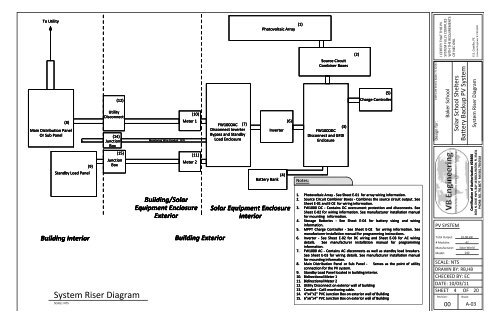
System Riser Diagram<br />
SCALE: NTS<br />
Monitoring Wire Conduit (13)<br />
(10)<br />
Meter 1<br />
(11)<br />
Meter 2<br />
Building/<strong>Solar</strong><br />
Equipment Enclosure<br />
Exterior<br />
Building Exterior<br />
FW1000AC (7)<br />
Disconnect Inverter<br />
Bypass and Standby<br />
Load Enclosure<br />
(1)<br />
Photovoltaic Array<br />
Inverter Inverter<br />
(4)<br />
Battery Bank<br />
(6)<br />
<strong>Solar</strong> Equipment Enclosure<br />
Interior<br />
Notes:<br />
Source Circuit<br />
Combiner Boxes<br />
(3)<br />
FW1000DC<br />
Disconnect and GFDI<br />
Enclosure<br />
(2)<br />
(5)<br />
Charge Controller<br />
1. Photovoltaic Array - See Sheet E-01 for array wiring information.<br />
2. Source Circuit Combiner Boxes - Combines the source circuit output. See<br />
Sheet E-01 and E-02 for wiring information.<br />
3. FW1000 DC - Contains DC overcurrent protection and disconnects. See<br />
Sheet E-02 for wiring information. See manufacturer installation manual<br />
for mounting information.<br />
4. Storage Batteries - See Sheet E-04 for battery sizing and wiring<br />
information.<br />
5. MPPT Charge Controller - See Sheet E-02 for wiring information. See<br />
manufacturer installation manual for programming instructions.<br />
6. Inverter - See Sheet E-02 for DC wiring and Sheet E-03 for AC wiring<br />
details. See manufacturer installation manual for programming<br />
information.<br />
7. FW1000 AC - Contains AC disconnects as well as standby load breakers.<br />
See Sheet E-03 for wiring details. See manufacturer installation manual<br />
for mounting information.<br />
8. Main Distribution Panel or or Sub Panel - Serves Serves as the point of utility<br />
connection for the PV system.<br />
9. Standby Load Panel located in building interior.<br />
10. Bidirectional Meter 1<br />
11. Bidirectional Meter 2<br />
12. Utility Disconnect on exterior wall of building<br />
13. Conduit - Cat5 monitoring cable.<br />
14. 4"x4"x2" PVC Junction Box on exterior wall of Building<br />
15. 6"x6"x4" 6"x6"x4" PVC PVC Junction Junction Box Box on on exterior exterior wall wall of of Building<br />
Building<br />
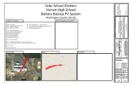
1369 14th Street, Baker, FL 32531<br />
Design for:<br />
I CERTIFY THAT THIS PV<br />
SYSTEM FULLY COMPLIES<br />
WITH THE REQUIREMENTS<br />
OF NEC 690.<br />
PV SYSTEM<br />
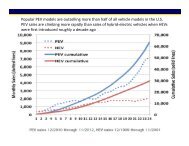
Total Output:<br />
# Modules:<br />
Manufacturer:<br />
Model:<br />
Baker School<br />
<strong>Solar</strong> School Shelters<br />
Battery Backup PV System<br />
System Riser Diagram<br />
SCALE: NTS<br />
DRAWN BY: RB,HB<br />
CHECKED BY: EC<br />
DATE: 10/03/11<br />
SHEET 4 OF 20<br />
Revision:<br />
00<br />
10.08 kW<br />
42<br />
<strong>Solar</strong> World<br />
240<br />
Sheet:<br />
E.E. Castillo, PE<br />
Licensed Engineer #: PE52590<br />
Certification of Authorization #28406<br />
3601 N. DIXIE HWY, BAY 16 BOCA RATON, FL 33431<br />
PHONE: 561.750.8677 FAX:561.750.0518<br />
A-03