Permit PackageBakerSchoolOkaloosa.pdf - Florida Solar Energy ...
Permit PackageBakerSchoolOkaloosa.pdf - Florida Solar Energy ...
Permit PackageBakerSchoolOkaloosa.pdf - Florida Solar Energy ...

You also want an ePaper? Increase the reach of your titles
YUMPU automatically turns print PDFs into web optimized ePapers that Google loves.
1 1/4" conduit<br />
(4) #4 &<br />
(1) #10 THWN-2 in<br />
1 1/4" conduit<br />
Utility Disconnect<br />
3P 100A<br />
JB<br />
JB<br />
L1 L2 L3<br />
100A 120/208 V<br />
Critical Load Panel<br />
Do not bond neutral<br />
to ground in meter<br />
can.<br />
Do not bond neutral<br />
to ground in meter<br />
can.<br />
50A<br />
Line side of 3-phase meter<br />
50A<br />
1" conduit<br />
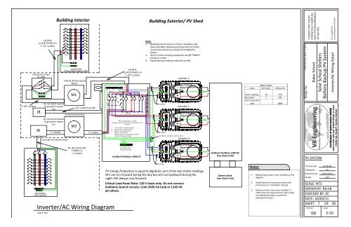
Building Interior Building Exterior/ PV Shed<br />
L1 L2 L3<br />
120/208 V MDP<br />
Minimum Busbar Ampacity = 300A<br />
3 Phase Bi-Directional<br />
Meter<br />
M1<br />
Bi-directional meter<br />
M2<br />
3/4" conduit w/cat5<br />
(4) #6 and (1) #10<br />
THWN-2 in<br />
1" conduit<br />
1" conduit<br />
N<br />
AC In<br />
Inverter/AC Wiring Diagram<br />
SCALE: NTS<br />
50A<br />
B<br />
(4) #4 &<br />
(1) #10 THWN-2 in<br />
1 1/4" conduit<br />
A<br />
ByPass<br />
B<br />
AC and DC Have<br />
Common Ground<br />
AC Out<br />
All Circuit breakers are 50A<br />
Switching sequence for A and B Inverter Bypass Circuit<br />
Breakers:<br />
1. A on and B off - Normal Operation<br />
2. B on and A off - Inverter Bypass<br />
3. Both off - No Standby Power<br />
4. Both on - Not Possible<br />
(Bypass breakers are mechanically linked to<br />
achieve indicated switching)<br />
OutBack FlexWare 1000 AC<br />
A<br />
B<br />
A<br />
Inverter AC Out<br />
Note:<br />
1. Building Interior Panels ( Critical / Standby Load<br />
Panel and Main Distribution/Array Point of Utility<br />
Connection Panel) Furnished and Installed by<br />
Others<br />
2. All AC current carrying conductors are #6 THWN-2<br />
except as noted.<br />
3. Equipment grounding conductors are #6.<br />
#6 THWN-2<br />
#6 THWN-2<br />
AC In<br />
H<br />
N<br />
AC Out<br />
H<br />
N<br />
AC In<br />
H<br />
N<br />
AC Out<br />
H<br />
N<br />
AC In<br />
H<br />
N<br />
AC Out<br />
H<br />
N<br />
-<br />
+<br />
-<br />
+<br />
(1) #10 Ground Wire to Each Inverter<br />
#6 THWN-2<br />
-<br />
+<br />
Inverter 1<br />
GVFX3648<br />
DC In<br />
Inverter 2<br />
GVFX3648<br />
DC In<br />
Inverter 3<br />
GVFX3648<br />
PV <strong>Energy</strong> Production is equal to algebraic sum of the two meter readings.<br />
M1 can run forward during the day but will run backward during the<br />
night. M2 always runs forward.<br />
Critical Load Panel Note: 120 V loads only. Do not connect<br />
multiwire branch circuits. Limit 3420 VA total or 1140 VA<br />
per phase.<br />
DC In<br />
DC In<br />
DC In<br />
DC In<br />
OutBack FlexWare 1000 DC<br />
(See Sheet E-02)<br />
Battery Bank<br />
(See Sheet E-04)<br />
Notes:<br />
1. Monitoring system is not included on this<br />
diagram.<br />
2. Install battery temperature sensor per<br />
instructions in installation manual.<br />
3. Revenue meter cans to be installed. If<br />
utility does not require them, then install<br />
reconditioned meters to perform<br />
indicated functions.<br />
1369 14th Street, Baker, FL 32531<br />
Design for:<br />
I CERTIFY THAT THIS PV<br />
SYSTEM FULLY COMPLIES<br />
WITH THE REQUIREMENTS<br />
OF NEC 690.<br />
PV SYSTEM<br />
Total Output:<br />
# Modules:<br />
Manufacturer:<br />
Model:<br />
Baker School<br />
<strong>Solar</strong> School Shelters<br />
Battery Backup PV System<br />
Inverter/AC Wiring Detail<br />
SCALE: NTS<br />
DRAWN BY: RB,HB<br />
CHECKED BY: EC<br />
DATE: 10/03/11<br />
SHEET 7 OF 20<br />
Revision:<br />
00<br />
10.08 kW<br />
42<br />
<strong>Solar</strong> World<br />
240<br />
Sheet:<br />
E.E. Castillo, PE<br />
Licensed Engineer #: PE52590<br />
Certification of Authorization #28406<br />
3601 N. DIXIE HWY, BAY 16 BOCA RATON, FL 33431<br />
PHONE: 561.750.8677 FAX:561.750.0518<br />
E-03