LASS user manual - audio concepts
LASS user manual - audio concepts
LASS user manual - audio concepts

Create successful ePaper yourself
Turn your PDF publications into a flip-book with our unique Google optimized e-Paper software.
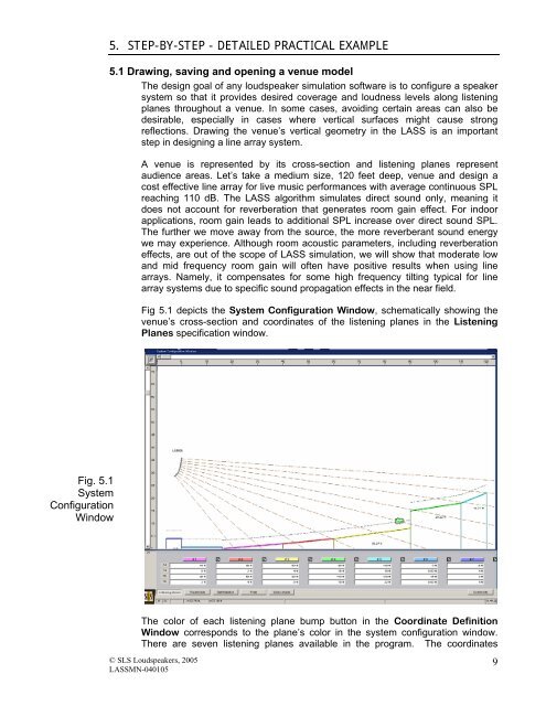
Fig. 5.1<br />
System<br />
Configuration<br />
Window<br />
5. STEP-BY-STEP - DETAILED PRACTICAL EXAMPLE<br />
5.1 Drawing, saving and opening a venue model<br />
The design goal of any loudspeaker simulation software is to configure a speaker<br />
system so that it provides desired coverage and loudness levels along listening<br />
planes throughout a venue. In some cases, avoiding certain areas can also be<br />
desirable, especially in cases where vertical surfaces might cause strong<br />
reflections. Drawing the venue’s vertical geometry in the <strong>LASS</strong> is an important<br />
step in designing a line array system.<br />
A venue is represented by its cross-section and listening planes represent<br />
audience areas. Let’s take a medium size, 120 feet deep, venue and design a<br />
cost effective line array for live music performances with average continuous SPL<br />
reaching 110 dB. The <strong>LASS</strong> algorithm simulates direct sound only, meaning it<br />
does not account for reverberation that generates room gain effect. For indoor<br />
applications, room gain leads to additional SPL increase over direct sound SPL.<br />
The further we move away from the source, the more reverberant sound energy<br />
we may experience. Although room acoustic parameters, including reverberation<br />
effects, are out of the scope of <strong>LASS</strong> simulation, we will show that moderate low<br />
and mid frequency room gain will often have positive results when using line<br />
arrays. Namely, it compensates for some high frequency tilting typical for line<br />
array systems due to specific sound propagation effects in the near field.<br />
Fig 5.1 depicts the System Configuration Window, schematically showing the<br />
venue’s cross-section and coordinates of the listening planes in the Listening<br />
Planes specification window.<br />
The color of each listening plane bump button in the Coordinate Definition<br />
Window corresponds to the plane’s color in the system configuration window.<br />
There are seven listening planes available in the program. The coordinates<br />
© SLS Loudspeakers, 2005<br />
<strong>LASS</strong>MN-040105<br />
9