

Boundary-layer height detection with a ceilometer at a coastal ... - Orbit
Boundary-layer height detection with a ceilometer at a coastal ... - Orbit
Boundary-layer height detection with a ceilometer at a coastal ... - Orbit

You also want an ePaper? Increase the reach of your titles
YUMPU automatically turns print PDFs into web optimized ePapers that Google loves.
SPIE Newsroom<br />
function of <strong>height</strong>, P (z) provides inform<strong>at</strong>ion on the backsc<strong>at</strong>ter profile of the <strong>at</strong>mosphere.<br />
It is measured by the instrument and is rel<strong>at</strong>ed to the emitted signal and the characteristics<br />
of the propag<strong>at</strong>ing medium through the lidar equ<strong>at</strong>ion: 10.1117/2.1200612.0512<br />
oundary <strong>layer</strong> and air quality<br />
onitoring <strong>with</strong> a commercial<br />
idar <strong>ceilometer</strong><br />
P (z) = P 0 ∆t c<br />
∫ z<br />
2z 2 Aβ(z)e−2 0 σ(z′ )dz ′ (15)<br />
where P 0 is the average power of the pulse [W], ∆t is the dur<strong>at</strong>ion of the emitted laser pulse<br />
[s], c is the speed of light [m/s], A is the receiver area [m 2 ], β(z) is the volume backsc<strong>at</strong>ter<br />
coefficient <strong>at</strong> distance z [1/(srad m)], σ(z’) is the extinction (<strong>at</strong>tenu<strong>at</strong>ion) coefficient <strong>at</strong> various<br />
distances z’ [1/m] and e −2 ∫ z<br />
0 σ(z′ )dz ′ is the <strong>at</strong>mospheric transmittance. When there is no<br />
<strong>at</strong>tenu<strong>at</strong>ion, in a clear <strong>at</strong>mosphere, the last term equals 1.<br />
hristoph Münkel<br />
roviding small, low-cost lidar systems <strong>with</strong> novel optical design and<br />
exible electronics sharpens the view of particles in the lower tropophere,<br />
and enables new environmental monitoring applic<strong>at</strong>ions.<br />
idar (light <strong>detection</strong> and ranging) remote sensing has enorous<br />
potential in <strong>at</strong>mospheric research and air quality<br />
onitoring, 1 made possible by the portion of emitted laser light<br />
<strong>at</strong> is sc<strong>at</strong>tered back to the instrument by particles in the <strong>at</strong>mophere.<br />
The recorded backsc<strong>at</strong>ter profiles could be used, for exmple,<br />
to estim<strong>at</strong>e the mixing <strong>layer</strong>’s aerosol density and thickess,<br />
or mixing <strong>height</strong> (MH). Substances introduced into the<br />
ixing <strong>layer</strong> become completely mixed by turbulence given sufcient<br />
time.<br />
These estim<strong>at</strong>es would be useful in helping comply <strong>with</strong> Euroean<br />
air quality framework directive 96/62/EC, which requires<br />
recise monitoring of pollution loading. The loading can be esti<strong>at</strong>ed<br />
using aerosol optical thicknesses retrieved from s<strong>at</strong>elliteased<br />
observ<strong>at</strong>ions, 2 together <strong>with</strong> the MH.<br />
High costs, scarcity, and eye-safety consider<strong>at</strong>ions exclude reearch<br />
lidar systems as a candid<strong>at</strong>e for a dense MH retrieval netork.<br />
I show here th<strong>at</strong> eye-safe lidar <strong>ceilometer</strong>s of the sort used<br />
report cloud base <strong>height</strong>s <strong>at</strong> most airfields can, <strong>with</strong> modst<br />
modific<strong>at</strong>ions introduced by Vaisala GmbH, provide a costffective<br />
altern<strong>at</strong>ive.<br />
The traditional <strong>ceilometer</strong> concentr<strong>at</strong>es on cloud base detecon<br />
using either a two-lens or a one-lens approach. The two-lens<br />
esign provides little or no laser beam and receiver field-of-view<br />
verlap for collecting aerosol backsc<strong>at</strong>ter in the near range up to<br />
00m, a crucial range for air quality applic<strong>at</strong>ions.<br />
The single-lens design, which uses the same lens for transmitng<br />
and receiving, provides full overlap over the whole meauring<br />
range, but requires compens<strong>at</strong>ing mechanisms to prevent<br />
eceiver s<strong>at</strong>ur<strong>at</strong>ion from direct lens reflections th<strong>at</strong> lower d<strong>at</strong>a<br />
uality in the near range. Poor range resolution, low pulse rep-<br />
Figure 1. Shown is the Vaisala Ceilometer CL31 and a schem<strong>at</strong>ic drawing<br />
of its optical concept. A hole in the mirror divides the lens into<br />
an inner part used by the transmitter and an outer ring visible to the<br />
receiver.<br />
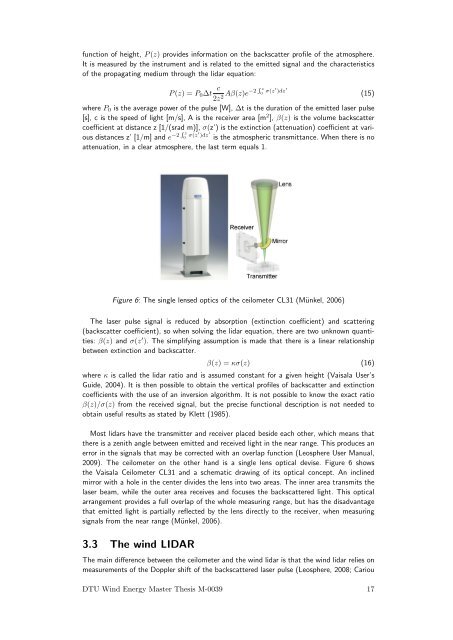
Figure 6: The single lensed optics of the <strong>ceilometer</strong> CL31 (Münkel, 2006)<br />
The laser pulse signal is reduced by absorption (extinction coefficient) and sc<strong>at</strong>tering<br />
(backsc<strong>at</strong>ter coefficient), so when solving the lidar equ<strong>at</strong>ion, there are two unknown quantities:<br />
β(z) and σ(z ′ ). The simplifying assumption is made th<strong>at</strong> there is a linear rel<strong>at</strong>ionship<br />
between extinction and backsc<strong>at</strong>ter.<br />
etition frequency, and long minimum report interval further decrease<br />
the performance of standard <strong>ceilometer</strong>s.<br />
The shortcomings of both designs are overcome by the novel<br />
optical design of the Vaisala Ceilometer CL31, shown in Figure 1.<br />
This instrument incorpor<strong>at</strong>es the advantages of both optical concepts,<br />
and the disadvantages of neither. Its fast electronics make<br />
it an all-purpose backsc<strong>at</strong>ter lidar, fit for standard <strong>ceilometer</strong><br />
tasks and air quality applic<strong>at</strong>ions. 3<br />
The right part of Figure 1 shows the enhanced single-lens design<br />
for the CL31. We use the center of the lens for collim<strong>at</strong>ing<br />
the outgoing laser beam, and the outer part to focus the backsc<strong>at</strong>tered<br />
light onto the receiver. This division between transmitting<br />
and receiving areas is provided by an inclined mirror <strong>with</strong> a hole<br />
β(z) = κσ(z) (16)<br />
where κ is called the lidar r<strong>at</strong>io and is assumed constant for a given <strong>height</strong> (Vaisala User’s<br />
Guide, 2004). It is then possible to obtain the vertical profiles of backsc<strong>at</strong>ter and extinction<br />
coefficients <strong>with</strong> the use of an inversion algorithm. It is not possible to know the exact r<strong>at</strong>io<br />
β(z)/σ(z) from the received signal, but the precise functional description is not needed to<br />
obtain useful results as st<strong>at</strong>ed by Klett (1985).<br />
Most lidars have the transmitter and receiver placed beside each other, which means th<strong>at</strong><br />
there is a zenith angle between emitted and received light Continued in the on next near page range. This produces an<br />
error in the signals th<strong>at</strong> may be corrected <strong>with</strong> an overlap function (Leosphere User Manual,<br />
2009). The <strong>ceilometer</strong> on the other hand is a single lens optical devise. Figure 6 shows<br />
the Vaisala Ceilometer CL31 and a schem<strong>at</strong>ic drawing of its optical concept. An inclined<br />
mirror <strong>with</strong> a hole in the center divides the lens into two areas. The inner area transmits the<br />
laser beam, while the outer area receives and focuses the backsc<strong>at</strong>tered light. This optical<br />
arrangement provides a full overlap of the whole measuring range, but has the disadvantage<br />
th<strong>at</strong> emitted light is partially reflected by the lens directly to the receiver, when measuring<br />
signals from the near range (Münkel, 2006).<br />
3.3 The wind LIDAR<br />
The main difference between the <strong>ceilometer</strong> and the wind lidar is th<strong>at</strong> the wind lidar relies on<br />
measurements of the Doppler shift of the backsc<strong>at</strong>tered laser pulse (Leosphere, 2008; Cariou<br />
DTU Wind Energy Master Thesis M-0039 17


