Click to download Ethernet Basics manual - Grant Industrial Controls
Click to download Ethernet Basics manual - Grant Industrial Controls
Click to download Ethernet Basics manual - Grant Industrial Controls

You also want an ePaper? Increase the reach of your titles
YUMPU automatically turns print PDFs into web optimized ePapers that Google loves.
<strong>Ethernet</strong> 31<br />
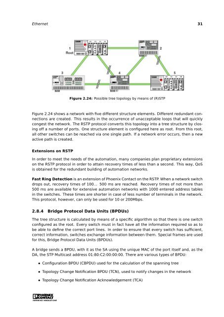
Figure 2.24: Possible tree <strong>to</strong>pology by means of (R)STP<br />
Figure 2.24 shows a network with five different structure elements. Different redundant connections<br />
are created. This results in the occurrence of unacceptable loops that will quickly<br />
congest the network. The RSTP pro<strong>to</strong>col converts this <strong>to</strong>pology in<strong>to</strong> a tree structure by closing<br />
off a number of ports. One structure element is configured here as root. From this root,<br />
all other switches can be reached via one single path. If a network error occurs, then a new<br />
active path is created.<br />
Extensions on RSTP<br />
In order <strong>to</strong> meet the needs of the au<strong>to</strong>mation, many companies plan proprietary extensions<br />
on the RSTP pro<strong>to</strong>col in order <strong>to</strong> attain recovery times of less than a second. This way, QoS<br />
is obtained for the redundant building of au<strong>to</strong>mation networks.<br />
Fast Ring Detection is an extension of Phoenix Contact on the RSTP. When a network switch<br />
drops out, recovery times of 100... 500 ms are reached. Recovery times of not more than<br />
500 ms are available for extensive au<strong>to</strong>mation networks with 1000 entered address tables<br />
in the switches. These times are shorter in case of less number of terminals in the network.<br />
This pro<strong>to</strong>col, however, can only be used for 10 or 200Mbps.<br />
2.8.4 Bridge Pro<strong>to</strong>col Data Units (BPDUs)<br />
The tree structure is calculated by means of a specific algorithm so that there is one switch<br />
configured as the root. Every switch must in fact have all the information required so as <strong>to</strong><br />
be able <strong>to</strong> define the correct port lines. In order <strong>to</strong> ensure that every switch has sufficient,<br />
correct information, switches exchange information between them. Special frames are used<br />
for this, Bridge Pro<strong>to</strong>col Data Units (BPDUs).<br />
A bridge sends a BPDU, with it as the SA using the unique MAC of the port itself and, as the<br />
DA, the STP Multicast address 01:80:C2:00:00:00. There are various types of BPDU:<br />
• Configuration BPDU (CBPDU) used for the calculation of the spanning tree<br />
• Topology Change Notification BPDU (TCN), used <strong>to</strong> notify changes in the network<br />
• Topology Change Notification Acknowledgement (TCA)