

LM391 Audio Power Driver
LM391 Audio Power Driver
LM391 Audio Power Driver

Create successful ePaper yourself
Turn your PDF publications into a flip-book with our unique Google optimized e-Paper software.
Application Hints (Continued)<br />
A 40W8X 60W4X AMPLIFIER<br />
Given<br />
<strong>Power</strong> Output<br />
40W8X<br />
60W4X<br />
1V Max<br />
100k<br />
20 Hz–20 kHz g 025 dB<br />
Input Sensitivity<br />
Input Impedance<br />
Bandwidth<br />
Equations (1) and (2) give<br />
40W8X V OPeak e 253V I OPeak e 316A<br />
60W4X V OPeak e 219V I OPeak e 548A<br />
Therefore the supply required is<br />
g303V 316A reducing to <br />
g269V 548A<br />
With 15% regulation and high line we get g383V using<br />
equation (3)<br />
The minimum gain from equation (4) is<br />
A V<br />
t 18<br />
We select a gain of 20 resulting sensitivity is 900 mV<br />
The input impedance and bandwidth are the same as the 20<br />
watt amplifier so the components are the same<br />
R f1 e 51k R IN e 100k C C e 5pF<br />
R f2 e100k C f e 10 mF<br />
The maximum supplies dictate using 80V devices The<br />
2N5882 2N5880 pair are 80V 160W transistors with a minimum<br />
beta of 40 at 2A and 20 at 6A This corresponds to a<br />
minimum beta of 225 at 55A (I Opeak ) The MJE712<br />
MJE722 driver pair are 80V transistors with a minimum beta<br />
of 50 at 250 mA This output combination guarantees I Opeak<br />
with 5 mA from the <strong>LM391</strong><br />
Output transistor heat sink requirements are found using<br />
equations (7) (9) and (10)<br />
P D e 04 (60) e 24W<br />
(7)<br />
200 b 55<br />
i JA<br />
s e 60CW for T AMAX e 55C (9)<br />
24<br />
i SA<br />
s 60 b 11 b 10 e 39CW (10)<br />
For both output transistors on one heat sink the thermal<br />
resistance should be 19CW<br />
Now using equation (8) we find the power dissipation in the<br />
driver<br />
P DRIVER e 24 e 12W (8)<br />
20<br />
150 b 55<br />
i JA<br />
s e 79CW (9)<br />
12<br />
Since a heat sink is required on the driver we should investigate<br />
the output stage thermal stability at the same time to<br />
optimize the design If we find a value of R E that is good for<br />
the protection circuitry we can then use equation (5) to find<br />
the heat sink required for the drivers<br />
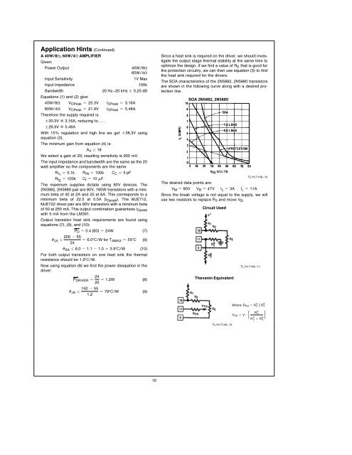
The SOA characteristics of the 2N5882 2N5880 transistors<br />
are shown in the following curve along with a desired protection<br />
line<br />
SOA 2N5882 2N5880<br />
TLH7146–10<br />
The desired data points are<br />
V M e 80V V B e 47V I L e 3A I L e 11A<br />
Since the break voltage is not equal to the supply we will<br />
use two resistors to replace R 3 and move V B <br />
Circuit Used<br />
Thevenin Equivalent<br />
TLH7146–11<br />
Where R TH e R A 3 ll R B 3<br />
V TH e V b R<br />
<br />
A 3<br />
R A 3 3( a RB<br />
TLH7146–12<br />
10


