TE-RTD12 User Manual - I.C.T. Power Company Inc.
TE-RTD12 User Manual - I.C.T. Power Company Inc.
TE-RTD12 User Manual - I.C.T. Power Company Inc.

Create successful ePaper yourself
Turn your PDF publications into a flip-book with our unique Google optimized e-Paper software.
Motortronics<br />
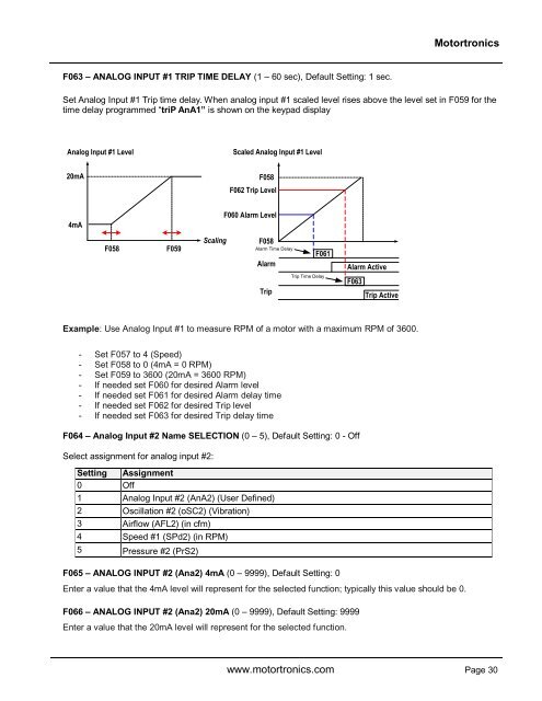
F063 – ANALOG INPUT #1 TRIP TIME DELAY (1 – 60 sec), Default Setting: 1 sec.<br />
Set Analog Input #1 Trip time delay. When analog input #1 scaled level rises above the level set in F059 for the<br />
time delay programmed “triP AnA1” is shown on the keypad display<br />
Analog Input #1 Level<br />
Scaled Analog Input #1 Level<br />
20mA<br />
F058<br />
F062 Trip Level<br />
4mA<br />
F060 Alarm Level<br />
F058<br />
F059<br />
Scaling<br />
F058<br />
Alarm Time Delay<br />
Alarm<br />
Trip<br />
F061<br />
Trip Time Delay<br />
Alarm Active<br />
F063<br />
Trip Active<br />
Example: Use Analog Input #1 to measure RPM of a motor with a maximum RPM of 3600.<br />
- Set F057 to 4 (Speed)<br />
- Set F058 to 0 (4mA = 0 RPM)<br />
- Set F059 to 3600 (20mA = 3600 RPM)<br />
- If needed set F060 for desired Alarm level<br />
- If needed set F061 for desired Alarm delay time<br />
- If needed set F062 for desired Trip level<br />
- If needed set F063 for desired Trip delay time<br />
F064 – Analog Input #2 Name SELECTION (0 – 5), Default Setting: 0 - Off<br />
Select assignment for analog input #2:<br />
Setting Assignment<br />
0 Off<br />
1 Analog Input #2 (AnA2) (<strong>User</strong> Defined)<br />
2 Oscillation #2 (oSC2) (Vibration)<br />
3 Airflow (AFL2) (in cfm)<br />
4 Speed #1 (SPd2) (in RPM)<br />
5 Pressure #2 (PrS2)<br />
F065 – ANALOG INPUT #2 (Ana2) 4mA (0 – 9999), Default Setting: 0<br />
Enter a value that the 4mA level will represent for the selected function; typically this value should be 0.<br />
F066 – ANALOG INPUT #2 (Ana2) 20mA (0 – 9999), Default Setting: 9999<br />
Enter a value that the 20mA level will represent for the selected function.<br />
www.motortronics.com Page 30