TE-RTD12 User Manual - I.C.T. Power Company Inc.
TE-RTD12 User Manual - I.C.T. Power Company Inc.
TE-RTD12 User Manual - I.C.T. Power Company Inc.

You also want an ePaper? Increase the reach of your titles
YUMPU automatically turns print PDFs into web optimized ePapers that Google loves.
Motortronics<br />
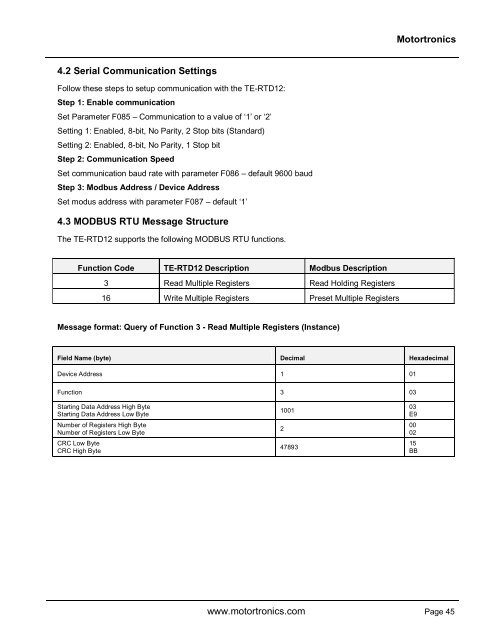
4.2 Serial Communication Settings<br />
Follow these steps to setup communication with the <strong>TE</strong>-<strong>RTD12</strong>:<br />
Step 1: Enable communication<br />
Set Parameter F085 – Communication to a value of ‘1’ or ‘2’<br />
Setting 1: Enabled, 8-bit, No Parity, 2 Stop bits (Standard)<br />
Setting 2: Enabled, 8-bit, No Parity, 1 Stop bit<br />
Step 2: Communication Speed<br />
Set communication baud rate with parameter F086 – default 9600 baud<br />
Step 3: Modbus Address / Device Address<br />
Set modus address with parameter F087 – default ‘1’<br />
4.3 MODBUS RTU Message Structure<br />
The <strong>TE</strong>-<strong>RTD12</strong> supports the following MODBUS RTU functions.<br />
Function Code <strong>TE</strong>-<strong>RTD12</strong> Description Modbus Description<br />
3 Read Multiple Registers Read Holding Registers<br />
16 Write Multiple Registers Preset Multiple Registers<br />
Message format: Query of Function 3 - Read Multiple Registers (Instance)<br />
Field Name (byte) Decimal Hexadecimal<br />
Device Address 1 01<br />
Function 3 03<br />
Starting Data Address High Byte<br />
Starting Data Address Low Byte<br />
Number of Registers High Byte<br />
Number of Registers Low Byte<br />
CRC Low Byte<br />
CRC High Byte<br />
1001<br />
2<br />
47893<br />
03<br />
E9<br />
00<br />
02<br />
15<br />
BB<br />
www.motortronics.com Page 45