TE-RTD12 User Manual - I.C.T. Power Company Inc.
TE-RTD12 User Manual - I.C.T. Power Company Inc.
TE-RTD12 User Manual - I.C.T. Power Company Inc.

You also want an ePaper? Increase the reach of your titles
YUMPU automatically turns print PDFs into web optimized ePapers that Google loves.
Motortronics<br />
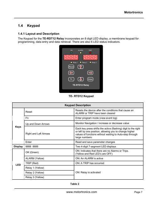
1.4 Keypad<br />
1.4.1 Layout and Description<br />
The Keypad for the <strong>TE</strong>-RDT12 Relay incorporates an 8 digit LED display, a membrane keypad for<br />
programming, data entry and data retrieval. There are also 6 LED status indicators.<br />
OK ALARM TRIP<br />
Relay 1 Relay 2 Relay 3<br />
Reset<br />
Fn<br />
Enter<br />
<strong>TE</strong>-<strong>RTD12</strong> Relay<br />
<strong>TE</strong>- <strong>RTD12</strong> Keypad<br />
Keypad Description<br />
Reset<br />
Fn<br />
Resets the device after the conditions that cause an<br />
ALARM or TRIP have been cleared<br />
Enter program mode (view event log)<br />
Keys<br />
Up and Down Arrows<br />
Right and Left Arrows<br />
Enter<br />
Monitor Navigation / increase or decrease value<br />
Each key press shifts the active (flashing) digit to the right<br />
or left by one position, allowing you to change higher<br />
values of functions without waiting to Auto-step through<br />
large numbers.<br />
Read and save parameter changes<br />
Display 8888 8888 Two 4-digit 7-segment LED displays<br />
LED<br />
OK (Green)<br />
ALARM (Yellow)<br />
TRIP (Red)<br />
Relay 1 (Yellow)<br />
Relay 2 (Yellow)<br />
Relay 3 (Yellow)<br />
Table 2<br />
ON: Indicates that there are no Alarms or Trips.<br />
(Yellow and Red LED’s are OFF)<br />
ON: An ALARM is active<br />
ON: A TRIP has occurred<br />
ON: Relay is activated<br />
www.motortronics.com Page 7